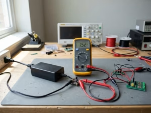
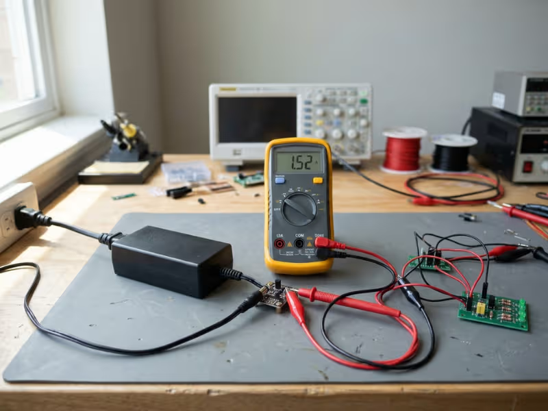
A controller board runs perfectly on a lab bench supply. Then the team switches to the production adapter, and the device starts resetting at random. The label voltage is correct, and the wattage looks fine on paper. The fastest way to find the cause is to measure current draw from a power adapter under real operating conditions.
A current reading often resolves the problem in minutes. A motor may pull twice its rated current at startup. The adapter may sag during a load spike. Or the adapter may be fine, and a thin cable is dropping the voltage. Without measured data, you are guessing.
This guide is written for hardware engineers, test technicians, and ODM sourcing teams. It covers series wiring, load testing, abnormal readings, and how to use your measurements to choose the right adapter from Quankang’s power supply range or any other source. Scope: everything here applies to the low-voltage DC output side of an adapter. Mains-side measurement is outside the scope of routine engineering work.
Quick answer: How do you measure current draw from a power adapter?
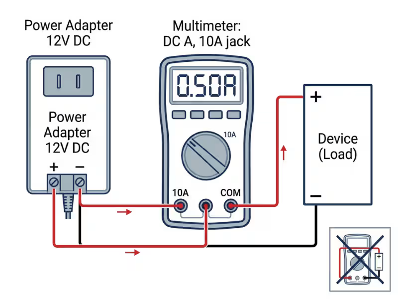
Connect a multimeter in series with the adapter’s positive DC output line:
- Unplug the adapter and disconnect the device.
- Set the multimeter to DC amps (A⎓).
- Move the red lead to the 10A jack. Keep the black lead in COM.
- Open the positive DC line between the adapter and the device.
- Connect adapter (+) to the red lead, and the black lead to device (+).
- Plug in the adapter, power on the device, and read the current.
Start on the highest range. Switch to the mA jack only if the reading is below about 400mA.
Key takeaways:
- Current is measured in series, never in parallel. In current mode, a meter placed across the adapter output acts as a short circuit.
- Test the DC output side only. The AC input carries hazardous mains voltage and is not part of routine adapter validation.
- Measure under real load. With no load, an adapter shows 0A and a misleadingly high voltage.
- Capture peaks, not just averages. Motors, heaters, and radios create surges that a quick reading misses.
- Size the adapter from the data. Add 20–30% headroom above measured peak steady-state current, then check thermal derating.
What Is Current Draw?
Current draw is the electric current a device pulls from its power source while operating, measured in amperes (A). The device, or load, determines how much current flows. The power adapter sets the output voltage and defines the maximum current it can safely deliver.
Current Draw vs. Rated Output Current
Engineers and buyers often mix up these two numbers. The difference affects every sizing decision.
- Rated output current is printed on the adapter label, such as “24V ⎓ 2.5A.” It is the maximum continuous current the adapter can supply while staying within spec.
- Current draw is what your device actually pulls. It changes with operating mode, temperature, firmware state, and load.
A 24V 2.5A adapter powering a device that draws 1.2A supplies only 1.2A. The adapter does not force its full rating into the device. That is why a higher-current adapter at the correct voltage is generally safe to use.
Power links the two numbers: P = V × I. A 24V device drawing 1.5A consumes 36W. Add 25% headroom and you need about 45W, so a 24V 2A (48W) adapter fits with margin to spare.
Why Engineers Measure Current Draw
Current measurement supports decisions across the entire product lifecycle:
- Adapter sizing: Confirm the rating covers real-world peaks, not just datasheet averages.
- Prototype validation: Verify that sleep, idle, and active power modes behave as the firmware intends.
- Troubleshooting: Trace random resets, dim displays, or overheating back to a power issue.
- Battery charging checks: Confirm charge current at each stage of the charge profile.
- Thermal planning: Current through cables and connectors produces heat you must manage.
- Incoming inspection: Compare production adapters against the approved golden sample.
These checks apply to every device category, from patient monitors to PoE cameras. You can see how current requirements shape real designs on Quankang’s applications page.
DC Output vs. AC Input: Which Side Should You Test?
Every AC-DC adapter has two sides. The primary side connects to 100–240V AC mains. The secondary side delivers isolated low-voltage DC to your device. Adapter current validation happens on the secondary side.
Factor | DC Output (Secondary) Side | AC Input (Primary) Side |
|---|---|---|
Typical voltage | 5–48V DC | 100–240V AC |
Shock hazard | Low (SELV range for most adapters) | High, potentially lethal |
What you learn | Device current draw, load behavior, regulation | Input power, efficiency, power factor |
Recommended tool | Multimeter in series, DC electronic load | Plug-in power meter or power analyzer |
Who should test | Engineers and trained technicians | Qualified personnel only |
This guide covers DC output testing only. Never open an adapter housing or cut into the AC cord to insert a meter.
If you need input power or efficiency data, place a plug-in power meter between the wall outlet and the adapter. It reads watts and current without exposing live conductors. Detailed mains-side measurement belongs in a properly equipped lab, handled by qualified personnel using appropriately rated equipment.
Tools You Need to Measure Adapter Current Draw
A basic current check needs only a multimeter and a safe way to open the DC line. Full adapter validation calls for a few more instruments.
Tool | Purpose | What to Look For |
|---|---|---|
Digital multimeter (DMM) | Measures DC current in series | Fused 10A and mA inputs, DC A range, MIN/MAX or peak capture |
DC breakout cable or barrel-jack adapter | Opens the positive line without cutting the production cable | Matches connector size and current rating |
Insulated alligator clip leads | Secures connections hands-free | Rated for the expected current |
Second multimeter | Monitors voltage at the device during current tests | Any reliable DMM |
DC electronic load | Applies controlled, repeatable load | Constant current (CC) mode, rated above adapter max power |
USB-C inline power meter | Measures USB PD voltage and current without splicing | Passes CC lines; supports EPR for tests above 20V |
PoE tester | Measures PoE voltage, current, and class inline | Supports 802.3af/at/bt as needed |
Oscilloscope with current probe | Captures inrush current and ripple | 20 MHz bandwidth limit for ripple tests |
Thermocouple or thermal camera | Tracks temperature rise under load | Reads case and connector temperature |
A Note on USB-C PD and PoE
USB-C PD and PoE negotiate power digitally. Splicing a multimeter into these cables can break negotiation or damage a port. Use an inline meter designed for the protocol instead.
For USB-C designs, our guide to USB PD chargers for medical devices explains why negotiation behavior matters. Quankang’s USB PD chargers support USB-C Power Delivery up to PD 3.1, and our PoE adapters cover 802.3af, 802.3at, and 802.3bt.
Safety Precautions for Low-Voltage DC Testing
Low-voltage DC is far safer than mains AC. Even so, shorted outputs, blown meter fuses, and hot connectors are common bench accidents. Follow these rules on every test:
- Make all connections with power off. Apply power only after every clip is secure.
- Never measure current in parallel. Meter leads across the adapter output in current mode create a dead short.
- Start on the 10A range. Step down to mA only after confirming the current is small.
- Respect the meter’s time limit. Many DMMs allow 10A for only about 30 seconds before a cool-down period.
- Use a meter with fused current inputs. Replace a blown fuse only with the exact rating and type the meter maker specifies.
- Watch connector heat. Undersized breakout cables can run hot at several amps.
- Stay on the secondary side. Never open an adapter enclosure while it is plugged into mains.
- Treat batteries with care. Battery-backed devices can deliver high fault current even with the adapter unplugged.
With your tools ready and safety rules in place, you can run the measurement.
How to Measure Current Draw from a Power Adapter: 7 Steps
This procedure takes about 15 minutes. It works for barrel-connector and screw-terminal adapters from 5V to 48V.
Step 1: Check the Adapter and Device Ratings
Read the adapter label (for example, 12V ⎓ 3A) and the device’s input rating. Estimate expected current from the device’s power spec. A 12V device rated at 18W should draw about 1.5A at full load, which tells you which jack and range to use.
Step 2: Power Down and Disconnect
Unplug the adapter from the wall outlet and disconnect the device. If the device contains a battery, disconnect it or confirm that the battery path won’t distort your reading.
Step 3: Set the Multimeter to DC Current
Turn the dial to DC amps, marked A with a straight line or the “⎓” symbol. Move the red lead from the V/Ω jack to the 10A jack. Leave the black lead in COM.
Step 4: Open the Positive DC Line
Insert a DC breakout cable or barrel-jack adapter between the adapter and the device. This exposes the positive conductor without cutting the production cable. On screw-terminal designs, remove only the positive wire from the device terminal and leave the ground connection in place.
Step 5: Connect the Meter in Series
Route all device current through the meter:
- Connect the adapter’s positive output to the meter’s red (10A) lead.
- Connect the meter’s black (COM) lead to the device’s positive input.
- Keep the negative line connected directly between the adapter and the device.
Current now flows through the meter’s internal shunt. If you have a second meter, connect it across the device input to monitor voltage at the load.
Step 6: Power On and Record Readings
Plug in the adapter and power up the device. Record current and device voltage in each operating mode:
- Standby or idle
- Typical operation
- Maximum load (motors running, display at full brightness, radio transmitting)
Enable MIN/MAX mode to catch brief peaks. If the reading stays below about 400mA, power down, move the red lead to the mA jack, and repeat for better resolution.
Step 7: Power Down and Restore the Meter
Unplug the adapter before removing any leads. Then return the red lead to the V/Ω jack and switch the meter off. This habit prevents the most common meter accident: shorting a voltage source through the amps jack on your next measurement.
Special Cases: USB-C PD and PoE Devices
- USB-C PD: Place a USB-C inline power meter between the charger and the device. It displays negotiated voltage, current, and often the PD contract. For 5A or EPR tests, use an e-marked cable rated for that current.
- PoE: Place an inline PoE tester between the PSE (injector or switch) and the powered device. Don’t break Ethernet pairs to insert a multimeter. Our guide to 802.3bt PoE adapters explains how to budget for peak PoE loads such as heaters and PTZ motors.
How to Load-Test Adapter Output
Measuring your device’s current draw tells you what it needs. Load-testing the adapter tells you whether it can deliver that current reliably. Proper validation requires both.
Why No-Load Readings Mislead
With nothing connected, an adapter delivers 0A, and its voltage often reads slightly above nominal. A 12V adapter may show 12.3V open-circuit and drop to 11.6V at full load. A no-load check only proves the adapter turns on. It reveals nothing about regulation, heat, or protection behavior.
Test with a DC Electronic Load
A DC electronic load in constant current (CC) mode produces precise, repeatable results. Step through 0%, 25%, 50%, 75%, and 100% of rated current. These match the load points used for DoE Level VI average efficiency testing.
At each step, record:
- Output current (from the load display or your series meter)
- Output voltage measured at the connector
- Adapter case temperature once the reading stabilizes
Then calculate load regulation:
Load regulation (%) = (V at no load − V at full load) ÷ V nominal × 100
Quality adapters typically hold regulation within about ±5% across the load range. Sensitive analog and medical designs often need tighter limits.
Test with the Real Device
An electronic load can’t reproduce every real-world behavior. Motors, heaters, LED drivers, and RF modules create dynamic loads with fast transients. After the electronic load test, repeat the series measurement with the actual device. Cycle through every mode, including cold startup, and log the worst-case peak.
Check Overcurrent Protection
Briefly raise the electronic load to about 110–130% of rated current. A well-designed adapter should limit current, fold back, or enter hiccup mode, then recover once the overload is removed. Keep this test short. Never perform it by shorting the output with meter leads.
Run a Thermal Soak
Run the adapter at 100% rated load for one to two hours, ideally at your application’s maximum ambient temperature. Watch for voltage drift, rising case temperature, or shutdown. Adapters that pass a quick bench test can still fail inside a warm, sealed enclosure.
Sample Adapter Load Test Log
Load Point | Current (A) | Voltage at Connector (V) | Case Temp (°C) | Pass/Fail |
|---|---|---|---|---|
0% | 0.00 | 12.18 | 26 | Pass |
25% | 0.75 | 12.10 | 31 | Pass |
50% | 1.50 | 12.04 | 37 | Pass |
75% | 2.25 | 11.97 | 44 | Pass |
100% | 3.00 | 11.91 | 52 | Pass |
Sample log for a 12V 3A adapter at 25°C ambient. Set your own limits based on application and ambient conditions.
In this example, load regulation is (12.18 − 11.91) ÷ 12 × 100 ≈ 2.3%, well inside a ±5% target.
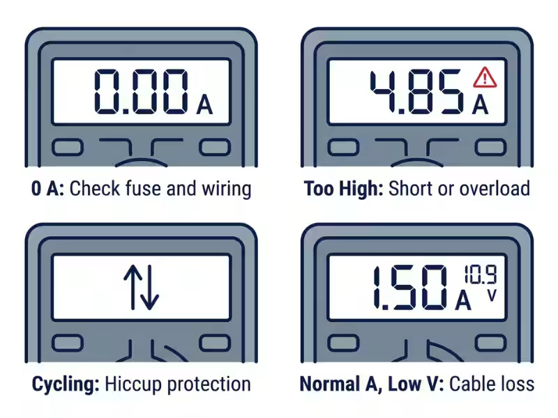
What Abnormal Current Readings Mean
Unexpected readings are useful data. Each pattern points to a short list of likely causes.
Reading | Likely Cause | What to Check Next |
|---|---|---|
0A with device running | Meter not in the current path, blown meter fuse, lead in the wrong jack | Confirm series wiring; test the fuse with continuity mode |
0A, device off | Adapter not powered, open circuit, adapter in protection | Measure adapter voltage at no load |
Current far above estimate | Short on the device, stalled motor, failed component, wrong voltage | Check device voltage; inspect for heat or damage |
Current cycles between high and near zero | Adapter in hiccup mode due to overload | Compare peak draw to rating; check inrush current |
Fluctuating current | Pulsed or dynamic load, loose connection, poor regulation | Secure clips; check voltage stability on an oscilloscope |
Normal current, low voltage at device | Cable loss, connector resistance, adapter sag | Measure voltage at both adapter and device ends |
Current slowly climbs over time | Thermal drift in the device or a failing component | Log current during a thermal soak |
Device misbehaves only with meter inserted | Burden voltage from the meter shunt | Use a lower-resistance range or a dedicated current shunt |
If your readings show an adapter running at or beyond its limit, the fix is usually a higher-rated or better-regulated supply. Compare options in Quankang’s ITE power supply range for industrial and commercial equipment.
Multimeter vs. Clamp Meter for Adapter Testing
Both tools measure current, but they suit different jobs.
Factor | Multimeter (Series) | DC Clamp Meter |
|---|---|---|
Connection | Breaks the circuit; current flows through the meter | Clamps around one conductor; no circuit break |
Low-current resolution | Excellent, down to µA or mA | Limited; often 10mA or coarser |
Accuracy at adapter currents | High, typically about 1% or better | Moderate; drifts without zeroing |
Maximum current | Usually 10A, often time-limited | Tens to hundreds of amps |
Effect on circuit | Adds burden voltage | Negligible |
Best for | Adapter validation, standby current, small devices | High-current DC buses, quick checks without disassembly |
Standard clamp meters measure AC only. To read DC, you need a Hall-effect clamp meter with a DC A function. Zero it before each reading and clamp only one conductor. Clamping positive and negative together cancels the field and reads near zero.
For most adapter work under 10A, a multimeter in series is the more accurate choice.
6 Common Mistakes When Measuring Adapter Current
1. Connecting the Meter in Parallel
In current mode, a multimeter is close to a short circuit. Touching the leads across an adapter output triggers short-circuit protection. Across a battery, it can blow the meter fuse instantly or cause arcing.
2. Using the Wrong Jack or Range
Pushing 2A through a mA jack fused for 400mA will blow that fuse. Always begin on the 10A jack and step down only when the reading is small.
3. Missing a Blown Fuse
A meter that reads voltage but shows 0A in current mode often has a blown current fuse. Check it with continuity mode. Replace it only with the specified high-breaking-capacity type.
4. Forgetting to Move the Red Lead Back
Leaving the red lead in the 10A jack and then measuring voltage shorts the source through the meter. Build lead restoration into your shutdown routine.
5. Overlooking Burden Voltage
The meter’s shunt drops voltage, often tens of millivolts per amp on the 10A range and more on mA ranges. On a 3.3V or 5V rail, that drop can push a device into brownout. If behavior changes when the meter is inserted, suspect burden voltage first.
6. Trusting Averages for Peaks
A standard DMM updates only a few times per second. It can miss inrush and millisecond surges entirely. Use MIN/MAX mode, or capture transients with an oscilloscope and current probe.
What Current Draw Reveals About Power Supply Quality
Current measurement is a window into adapter design quality. Combined with voltage and temperature data, it shows how a supply will hold up in the field.
Load Regulation
A well-designed adapter keeps output voltage stable from light load to full load. Large voltage drops as current rises point to weak feedback design, undersized components, or thin output cables.
Ripple and Noise
A multimeter can’t show ripple because it reports an averaged value. If current draw looks normal but your device shows noisy sensor readings or audio hum, measure ripple with an oscilloscope. Use a 20 MHz bandwidth limit and a short ground spring at the output connector.
Supply topology strongly affects ripple and noise. Our guide to linear vs. switching power supplies explains the tradeoffs.
Thermal Design
More current means more heat in the transformer, rectifiers, and cable. Plot case temperature against current during a thermal soak. If temperature keeps climbing after an hour at rated load, the design has little thermal margin.
Transient Response
Motors and radios switch loads on and off quickly. A quality adapter recovers from a load step within microseconds to a few milliseconds without dipping below the device’s minimum voltage. Resets that line up with load changes point to weak transient response.
Efficiency
Measure input power with a plug-in power meter and output power as V × I at the connector. Efficiency equals output divided by input. Low efficiency wastes energy, adds heat, and can block compliance with DoE Level VI or EU Ecodesign rules.
A note for medical device teams: Current draw testing does not replace leakage current testing. IEC 60601-1 leakage measurements require a dedicated tester with a specified measuring network, not a standard multimeter. Quankang’s medical power supplies are designed for leakage current ≤100µA with 2x MOPP isolation, and certification files are available with samples.
How to Choose the Right Power Adapter Based on Measured Current
With real measurements in hand, adapter selection becomes a structured decision. Work through these six points:
- Start from measured peak steady-state current, not the datasheet’s typical value.
- Add 20–30% headroom. A device that peaks at 2A steady-state needs an adapter rated for at least 2.5A.
- Account for inrush and surges. Motors and large input capacitors can draw several times running current at startup. Confirm that adapter protection won’t trip during power-up.
- Apply thermal derating. Many adapters lose usable output above 40°C ambient. Check the derating curve against your enclosure temperature.
- Match cable and connector ratings. Long or thin cables cause voltage drop at higher currents. Specify cable gauge and length with the adapter.
- Confirm certifications for your market, such as IEC 62368-1 for ITE equipment or IEC 60601-1 for medical devices.
Application | Typical Current Profile | Recommended Adapter Type |
|---|---|---|
Patient monitors, infusion pumps, sleep monitors | Low to moderate, ripple-sensitive | |
PLCs, POS terminals, routers | Steady 12V/24V loads | |
IP cameras, access points, VoIP phones | Peaks from heaters, IR, and PTZ motors | |
Laptops, tablets, portable medical carts | Variable, negotiated voltage | |
Non-standard voltage, connector, or housing | Application-specific |
When no standard model fits your measured profile, a custom design can set the exact voltage, current, connector, and cable. Our guide to custom power adapter ODM explains how to compare ODM quotes beyond unit price. You can also browse the full Quankang product range to find the closest standard match.
Have your current measurements ready?
Send Quankang your measured idle, typical, and peak current, plus voltage and certification needs. Our FAE team returns a compliance gap analysis within 24 hours. Functional samples with preliminary EMC reports ship in about 10 days. Request a custom adapter quote.
How Quankang Validates Adapter Output Current
Every Quankang adapter is built to deliver its rated current reliably across its full temperature range and service life, not just on a room-temperature bench on day one. That reliability comes from a disciplined, documented process:
- 36 years of power conversion experience, backed by 212+ active patents
- ISO 13485-certified manufacturing for medical-grade power supplies
- In-house EMC lab that pre-scans every new design to FCC and CE standards
- 98.3% first-pass EMC compliance rate across 10,000+ OEM projects
- 100% AOI and ICT inspection on every PCB, with MES and SAP traceability
- 5W–1000W portfolio covering medical, ITE, PoE, and USB PD applications
- Shipped to 50+ countries, from clinical-trial pilots to high-volume production
The same process supports a 500-unit pilot and a 500,000-unit production run. See our production lines, test equipment, and quality systems on the Quankang facilities page.
Frequently Asked Questions
Can a multimeter measure current draw from a power adapter?
Yes. Set the multimeter to DC amps, move the red lead to the 10A jack, and connect the meter in series with the positive DC line between the adapter and the device. Most handheld multimeters handle up to 10A, often for a limited time, which covers most external adapters.
Why does my multimeter show 0 amps?
The most common causes are a blown current fuse, the red lead in the wrong jack, or a meter that isn’t actually in the current path. Confirm series wiring first, then test the fuse with continuity mode. If the device isn’t running, the adapter may be in protection mode.
Can I use a 3A adapter on a device that needs 2A?
Yes, as long as the voltage and polarity match exactly. The device draws only the current it needs, so a higher current rating adds safety margin. A lower-rated adapter, however, may overheat, sag, or shut down under peak load.
How do I measure current from a USB-C PD charger?
Use a USB-C inline power meter between the charger and the device. Splicing a multimeter into a USB-C cable can break PD negotiation. For high-power or EPR tests, use an e-marked cable and a meter that supports the negotiated voltage. See Quankang’s USB PD chargers.
How much current headroom should a power adapter have?
Plan for 20–30% above your device’s measured peak steady-state current. Then check the adapter’s derating curve at your maximum ambient temperature. Devices with motors or large input capacitors may need extra margin for startup surges.
Is it safe to measure current on the AC input side of an adapter?
Not for routine testing. The input side carries hazardous mains voltage. Use a plug-in power meter if you need input power or efficiency data. Direct mains-side current measurement belongs to qualified personnel using properly rated equipment in a controlled lab.
How do I measure inrush current?
A standard multimeter is too slow to capture inrush current. Use an oscilloscope with a current probe or a low-value current-sense resistor, triggered on power-up. Some meters offer an inrush or peak function, but an oscilloscope shows the full waveform and duration.
Does current draw testing replace leakage current testing for medical devices?
No. Leakage current under IEC 60601-1 requires a dedicated tester with a specified measuring network. Current draw testing confirms load behavior, while leakage testing confirms patient and operator safety. Quankang’s medical power supplies are designed for leakage current ≤100µA.
Conclusion: Measure First, Then Choose Your Adapter
When you measure current draw from a power adapter, guesswork turns into engineering data. A multimeter in series, an electronic load, and a structured test log show exactly what your device needs. They also show whether your adapter can deliver it under real conditions, including peaks, heat, and overload.
Put this guide to work on your next project:
- Measure idle, typical, and peak current on the DC output side, while monitoring voltage at the device.
- Load-test the adapter across its full range, including protection behavior and a thermal soak.
- Size the final adapter with 20–30% headroom, thermal derating, and the right certifications for your market.
When your measurements point to a better-fit supply, Quankang’s engineering team can help. Our 5W–1000W portfolio is built in an ISO 13485-certified facility, pre-scanned in our in-house EMC lab, and backed by 36 years of power conversion experience.
Need an adapter that matches your measured current profile?
Share your voltage, current, and certification requirements with Quankang’s engineers. Get a compliance gap analysis within 24 hours and samples with preliminary EMC reports in about 10 days.Request a Custom Quote | Browse All Power Supplies | Explore Medical Power Supplies