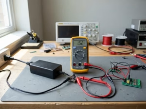

A batch of AC-DC adapters passes output voltage, load regulation, and ripple tests. It ships to an equipment maker and fails incoming safety inspection. The cause: a cable conductor pinched under the enclosure during ultrasonic welding. Every unit powered up normally. No functional test could have revealed the fault.
Hipot (high-potential) testing finds this kind of defect. It applies a voltage well above normal operating levels across an insulation barrier and confirms that the barrier holds without breakdown or excessive current. In a power adapter, the most critical barrier sits between the mains-connected primary and the low-voltage output that people touch.
This guide covers what the test checks in an adapter, how it runs on a production line, the AC vs. DC decision, pass/fail logic, and how hipot differs from other safety tests. It ends with the questions OEM buyers should ask before qualifying a supplier.
Hipot at a glance
- Also called: dielectric withstand test, dielectric voltage withstand test, electric strength test
- Main barrier in adapters: primary-to-secondary (plus primary-to-earth in Class I designs)
- Result type: pass/fail — it does not measure insulation quality
- Performed as: a type (certification) test, a routine production test, and occasionally a field test
- Test values: set by the applicable standard and approved procedure, never by rule of thumb
What Is Hipot Testing?
A hipot test applies a controlled high voltage between two groups of conductors that must stay electrically isolated. The tester monitors the current flowing across the insulation between them. Sound insulation allows only a small, predictable current through. If the insulation is too thin, contaminated, or damaged, current rises sharply or an arc forms.
Normal operating voltage proves nothing about safety margin. In service, an adapter sees mains surges, switching transients from nearby loads, and slow insulation degradation from heat and humidity. A barrier that only just survives 230V is not a safety barrier. Hipot stresses it well beyond its working voltage for a short, controlled time to prove the margin is real.
Buyers will encounter four names for the same test in supplier documents and certification reports:
- Hipot — shop-floor shorthand
- Dielectric withstand test or dielectric voltage withstand test — common in North American documents
- Electric strength test — the term used in IEC 62368-1 and IEC 60601-1
All four describe one procedure. A CB report that says “electric strength” and a production record that says “hipot” refer to the same check.
What a Pass Proves, and What It Doesn’t
A hipot pass is strong evidence on one narrow question. It is not a full safety verdict.
A pass proves | A pass does not prove |
|---|---|
The barrier withstood the specified voltage for the specified time | Long-term insulation life under heat, humidity, and vibration |
No breakdown or flashover occurred | Correct creepage and clearance design (a design evaluation) |
No gross assembly defect exists across that barrier | Earth continuity in Class I units |
Operating leakage or touch current | |
Output performance or protection functions |
Hipot confirms that manufacturing did not break an insulation system already approved through design review and certification. Within that scope it is very effective. Outside it, the test says nothing.
What Hipot Testing Checks in a Power Adapter
An isolated AC-DC adapter is built around one or two safety barriers, depending on its protection class. A hipot tester connects to each side of a barrier and stresses it. Class II adapters (two-pin mains input) rely on double or reinforced insulation. Class I adapters add a protective earth connection.
These IEC protection classes have nothing to do with “Class 2” power limits in North American codes or PoE power classes. They describe only how the user is protected from mains voltage.
Primary-to-Secondary: The Barrier That Protects the User
The secondary output reaches DC cables, connectors, and the end equipment — parts that operators and service staff touch. The barrier between hazardous mains voltage and that output is usually reinforced or double insulation. If it fails, mains potential can appear on a DC plug or on the chassis of the device it powers.
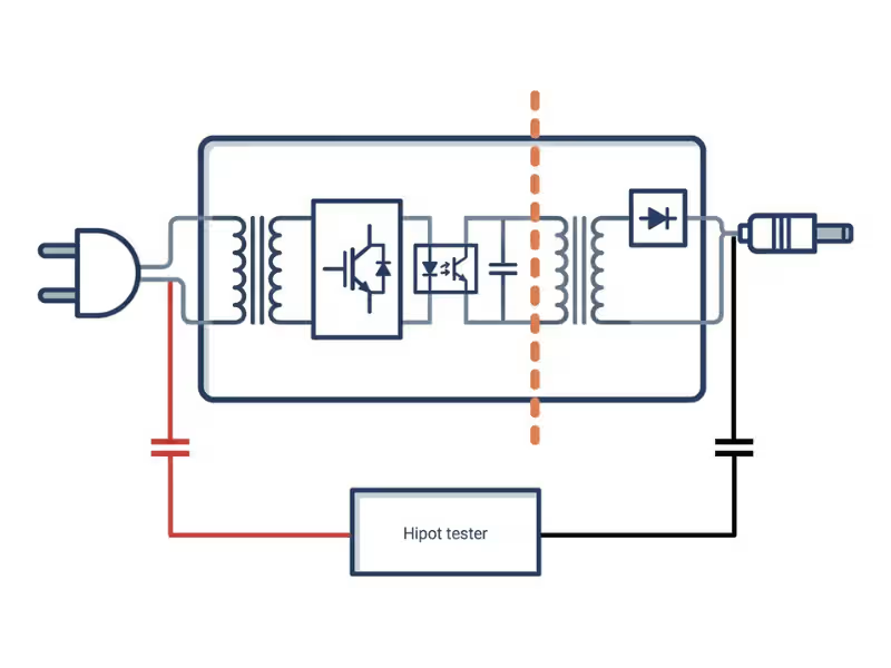
That barrier is not a single component. In a typical adapter it is formed by:
- The transformer insulation system: triple-insulated wire, insulation tape layers, and bobbin walls and margins
- Optocoupler isolation in the feedback loop
- PCB spacing: creepage distances and milled slots under the transformer and optocoupler
- Y capacitors that bridge the barrier for EMI suppression
- The enclosure, which keeps internal spacing intact and prevents contact with live parts
For the test, line and neutral are shorted together and connected to the high-voltage terminal. Output positive and negative are shorted together and connected to the return. This stresses the entire barrier at once and keeps the test voltage off individual circuits on either side. Skipping this shorting step is one of the most common setup errors on production lines.
Primary-to-Earth in Class I Designs
Class I adapters — common in higher-wattage desktop and industrial units — also rely on basic insulation between the primary circuit and earthed metal. That barrier is tested separately, usually at a lower voltage than the reinforced primary-to-secondary barrier, because basic insulation is backed up by the earth path.
That backup only works if the earth path is intact. Class I designs therefore also need a ground bond test, which hipot cannot replace. A unit with a broken earth connection can pass hipot cleanly.
Manufacturing Defects a Hipot Test Exposes
Most hipot failures on a mature product come from assembly, not design.
Defect | Where it happens | Why functional tests miss it |
|---|---|---|
Pinched or nicked wire insulation | Housing assembly, cable strain relief | The adapter still powers up normally |
Damaged transformer tape or bobbin | Winding, component insertion | Output voltage stays correct |
Solder bridges, flux residue, or debris across a creepage slot | SMT and wave soldering | No current path at working voltage |
Misplaced components that reduce spacing | Manual insertion | The circuit works as designed |
Weld or seal damage that displaces internal parts | Ultrasonic welding | Invisible from outside |
Moisture or contamination in insulation | Storage, potting, humid workshops | Only appears under high stress |
Every defect in this table leaves the adapter fully functional. That is precisely why hipot exists and why it cannot be replaced by more thorough output testing.
How a Hipot Test Works, Step by Step
A production hipot cycle on an adapter takes a few seconds. Each step still carries a failure mode if done carelessly.
- Prepare the unit. Disconnect it from any supply and load it into a fixture that shorts input and output conductors as the approved test instruction requires.
- Verify the connection. Run a contact or continuity check so an open lead or loose fixture cannot produce a false pass.
- Load the parameters. Set test voltage, trip current, ramp time, dwell time, and arc detection from the approved test instruction for that model and barrier.
- Ramp and hold. Raise the voltage smoothly to the test level, then hold it for the full dwell time.
- Monitor. The tester tracks current and arc events throughout the ramp and dwell.
- Discharge and record. Return the output to zero, discharge the unit (critical after DC testing), and log the result against the serial number.
On any credible production line, hipot stations use interlocked enclosures or two-hand controls, trained operators, and restricted access. Test voltages in the kilovolt range are lethal, and these controls are non-negotiable.
The Four Parameters That Define Every Hipot Test
Each setting should come from the applicable standard and the product’s approved procedure — not from habit or the previous model’s configuration.
Parameter | What it controls | Set too low | Set too high |
|---|---|---|---|
Test voltage | Stress across the barrier | Defects escape | Healthy insulation is damaged |
Trip current limit | Current that triggers a failure | False failures, especially with Y capacitors under AC | Real defects pass |
Ramp time | How fast voltage rises | Capacitive inrush causes false trips | Longer cycle time |
Dwell time | How long full voltage is held | Marginal defects escape | Unnecessary cumulative stress |
Many testers also offer arc detection, which flags brief discharges that never push average current over the limit. Arcs often indicate small air gaps, sharp solder points, or contamination that will degrade over time. A unit can stay under the trip current and still be arcing internally.
No universal correct value applies to every adapter. The right numbers depend on the barrier, the standard, the working voltage, and whether it is a type test or a routine test.
AC vs. DC Hipot: Which One Applies to Power Adapters?
Neither method is universally better. The applicable standard and approved procedure determine which is used, and both are common in adapter production.
Factor | AC hipot | DC hipot |
|---|---|---|
Stress applied | Alternating polarity, similar to mains | Single polarity |
Measured current | Capacitive plus resistive | Mostly resistive once the barrier has charged |
Effect of Y capacitors | Adds significant capacitive current | Minimal after the charge settles |
After the test | Little stored charge | Unit must be discharged before handling |
Equivalent voltage | Reference value (RMS) | Usually about 1.414 × the AC RMS value, where the standard allows substitution |
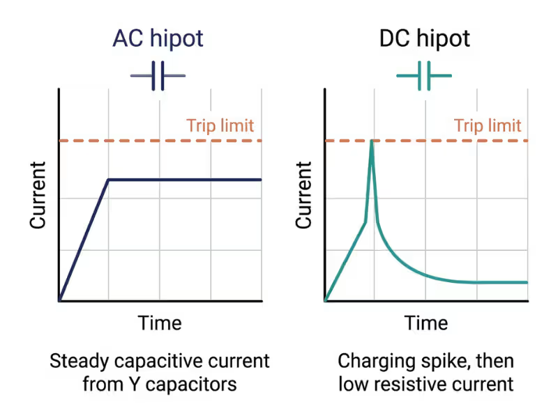
The method choice matters most in adapters because of the Y capacitors. These components intentionally bridge the primary-to-secondary barrier to control conducted EMI. Under AC hipot, they draw capacitive current that has nothing to do with insulation quality.
The current can be substantial. A 2.2nF Y capacitor at 3000 VAC and 60Hz draws about 2.5mA (I = 2πfCV). On a perfectly built unit, that figure alone can approach a typical production trip limit.
This creates pressure to raise the trip limit until false failures stop. A limit opened wide enough to absorb capacitor current will also absorb the extra current from a real insulation defect. The correct response is one of two options:
- Set the limit from measured current on known-good units, with a defined margin above it.
- Use DC hipot where the standard permits, because capacitive current collapses once the barrier charges.
When qualifying a supplier, ask which method they use on each barrier and why. A clear answer that mentions Y capacitors shows the supplier understands its own design. A vague answer suggests the settings were inherited rather than engineered.
The 1.414 factor is a reference relationship, not a value to copy. Take the actual DC equivalent from the standard or the certification report
.
How a Hipot Test Is Passed or Failed
Pass. The unit holds the full test voltage for the full dwell time, with no breakdown, no flashover, current below the trip limit, and no flagged arc (where arc detection is enabled).
Fail. Current exceeds the limit, a breakdown collapses the voltage, an arc is detected, or the connection check fails. That last case is a fixture or station failure — it must never be logged as a product pass, because the barrier was never actually tested.
What the current reading is not. The current shown during hipot flows under deliberate overvoltage stress. It is not touch current or patient leakage current. Those are measured under normal operating and single-fault conditions, using a measuring network that represents the human body. A hipot reading of 0.3mA says nothing about whether a medical adapter meets its leakage limit. Within the pass range, a lower hipot current does not mean better insulation.
Withstand vs. breakdown. Production hipot is a withstand test at a fixed level. A breakdown test raises voltage until insulation fails and is destructive. Breakdown testing belongs in material qualification and design evaluation, not on a production line.
Type Testing vs. Routine Production Testing vs. Field Testing
The same procedure serves three purposes at three stages of a product’s life. The conditions differ on purpose.
Stage | Purpose | Who performs it | Typical conditions |
|---|---|---|---|
Type (certification) test | Proves the design’s insulation system meets the standard | Certification lab or witnessed factory test | Full dwell (often 60 s), after preconditioning such as humidity treatment |
Routine production test | Proves each unit was assembled without breaching the barrier | Manufacturer, on 100% of units | Short dwell (often 1–3 s), sometimes at an adjusted voltage the standard permits |
Field or maintenance test | Checks installed equipment | Trained service personnel | Only under an approved maintenance procedure, often at reduced levels |
The most important point for buyers: a CB report proves the design passed once, on a small number of samples. It says nothing about unit number 40,000. Routine hipot on every unit is what carries that certification into each shipped product. A supplier with a strong CB report and a weak production test is relying on luck.
Ask for both — the certification report and evidence of the routine test: parameters per barrier, records, and station verification logs.
Repeated hipot adds cumulative stress to insulation. Retesting in rework loops or field service should follow a defined procedure, not habit.
Hipot vs. Insulation Resistance, Ground Bond, and Leakage Current Tests
Each electrical safety test answers a different question. None substitutes for another.
Test | Question it answers | Result type | Applies to |
|---|---|---|---|
Hipot | Does the barrier withstand overvoltage without breakdown? | Pass/fail | All isolated mains adapters |
Insulation resistance (IR) | How strongly does the insulation resist DC current? | Resistance in MΩ or GΩ | Design checks, incoming inspection, trend monitoring |
Ground bond / earth continuity | Is the protective-earth path complete and low-resistance under high current? | Resistance or pass/fail | Class I adapters |
Leakage / touch current | How much current reaches accessible parts in normal use and single-fault conditions? | µA, measured through a body-model network | All adapters; critical for medical |
The four tests fit together logically:
- Hipot confirms the barrier holds under stress.
- Ground bond confirms the backup path works if basic insulation fails (Class I).
- Leakage current shows what an operator or patient would actually experience in normal use.
- IR provides a numeric value that can be tracked over time, which hipot’s pass/fail cannot.
A supplier whose documentation says only “hipot tested” has answered one of these four questions.
Where Hipot Fits in a Power Adapter Production Test Sequence
Where hipot sits in the line matters as much as how it is set up. A test run before the final assembly step cannot catch damage introduced by that step.
A typical sequence:
- Incoming inspection of insulation materials, wire, and transformers
- PCB inspection (AOI and in-circuit testing)
- Final mechanical assembly and enclosure welding or sealing
- Burn-in or aging under load
- Hipot, plus ground bond for Class I units
- Final functional and output test (ATE)
- Visual inspection, labeling, and packing
Hipot belongs after enclosure welding and burn-in. Welding can crush internal wiring or shift components toward the barrier. Burn-in heat can expose marginal insulation that passed at room temperature. Running hipot before final ATE also ensures every unit that reaches output testing already has a verified barrier.
Sequences vary by factory, and a different order is not automatically wrong. The principle is consistent: hipot must follow every process step that could damage insulation.
What Changes for Medical and Industrial Power Supplies
The test method is the same across markets. What changes is the governing standard, the required insulation rating, and the consequence of a field failure.
Medical Power Supplies: MOPP, MOOP, and Higher Test Voltages
IEC 60601-1 defines insulation in terms of means of protection. MOOP (means of operator protection) covers people operating equipment. MOPP (means of patient protection) covers patients, who may be physically connected to equipment, unconscious, or have reduced skin resistance — and therefore require a higher level of protection.
Protection level | Typical electric strength test voltage (working voltage up to 250V) |
|---|---|
1×MOOP | 1500 VAC |
2×MOOP | 3000 VAC |
1×MOPP | 1500 VAC |
2×MOPP | 4000 VAC |
Reference values only. Confirm against the current edition of the standard and the device’s rated working voltage.
A 2×MOPP primary-to-secondary barrier tested at 4000 VAC is a significant step above typical ITE levels. It shapes transformer construction, creepage distances, and Y-capacitor selection. Smaller Y capacitors reduce leakage but increase EMI complexity. In medical design, hipot voltage and leakage limits must be engineered together — they cannot be resolved independently. Quankang’s medical power supplies are built around 2×MOPP isolation with leakage current controlled for patient-connected applications.
Industrial and ITE Power Supplies: Same Test, Harsher Life
ITE and most industrial adapters are evaluated under IEC 62368-1. Electric strength test values come from tables based on mains transient voltage and insulation grade. For reinforced insulation on 100–240V adapters, the required test is commonly around 3000 VAC — but always take the exact figure from the applicable table, not from a datasheet habit.
The standard sets the factory test. The installation sets the real stress. Industrial adapters face surges from motors and drives, heat in sealed enclosures, vibration, humidity, and conductive dust. Over time, these conditions erode insulation margin. A design that only just passes hipot at the factory has little left to lose.
Industrial buyers should ask about design margin and environmental preconditioning, not only the routine pass result. These considerations apply across Quankang’s ITE power supplies for industrial and networking equipment.
6 Common Hipot Testing Mistakes in Power Adapter Production
1. Opening the trip limit to stop Y-capacitor false failures.
This eliminates false failures and hides real defects at the same time. Set the limit from good-unit measurements with a defined margin, or use DC hipot where the standard allows.
2. Not shorting input and output conductors together.
Leaving parts of the barrier untested, or stressing internal semiconductors across their own junctions, produces unreliable results. Use a dedicated fixture that shorts each side consistently.
3. Skipping station verification.
A broken lead or failed relay reads as a pass on every unit. Verify each station at the start of every shift with a known-good unit and a known-fail reference.
4. Retesting failures at lower settings until they pass.
A failed unit is a quality event, not a retest candidate. Quarantine it, analyze the root cause, and determine whether the defect affects the rest of the batch.
5. Running hipot before the final mechanical step.
Damage from enclosure welding or final assembly escapes entirely. Test the finished, sealed unit.
6. Treating hipot current as leakage current.
Using the hipot reading in place of a leakage measurement creates false confidence, especially in medical technical files. Measure leakage separately, under the correct conditions and with the correct network.
What OEM Buyers Should Ask a Supplier About Hipot Testing
“Hipot tested” on a datasheet is a claim. These questions turn it into evidence.
Question | What a good answer looks like |
|---|---|
Which barriers are tested, at what voltage, current limit, and dwell? | Parameters stated per barrier and traceable to the standard |
Is hipot performed on 100% of units? | Yes, as a routine test — not by sampling |
Where in the line is it performed? | After final assembly and burn-in |
AC or DC, and how is the trip limit set? | A reasoned answer that addresses Y-capacitor current |
How are stations verified and calibrated? | Per-shift verification plus calibration records |
Are results logged by serial number? | Yes, through MES or equivalent traceability |
What happens to a failed unit? | Quarantine and root-cause analysis — no retest-to-pass |
Can you share the CB report and the routine test instruction? | Both available, under NDA if needed |
A supplier who answers all eight clearly and quickly has a real process. Vague answers to the first three are the clearest warning sign.
How Quankang Builds Hipot Testing into Power Adapter Production
At Quankang, hipot is part of a traceable production flow, not a standalone checkpoint. Finished units are tested after final assembly and aging, so welding and burn-in cannot introduce defects after the barrier has been verified. Every PCB also goes through AOI and in-circuit testing earlier in the line. Results are tracked by serial number through MES and SAP, so any test record can be traced back to its build data.
This process draws on 36 years of power conversion experience. Medical-grade supplies are manufactured under ISO 13485 certification, with designs achieving 2×MOPP isolation and leakage current at or below 100µA. The portfolio spans 5W to 1000W. You can review the production and test equipment behind these products. Where a standard model doesn’t match your insulation class, enclosure, or connector requirement, a custom power adapter can be engineered and certified for your specific application.
Qualifying a power adapter supplier?
Send Quankang your insulation class, target markets, and test requirements. The engineering team will return the applicable hipot parameters per barrier along with the relevant certification documents.
Start a custom adapter conversation
Frequently Asked Questions About Hipot Testing
What voltage is used to hipot test a power adapter?
It depends on the standard, the barrier, and the working voltage. Reinforced primary-to-secondary insulation on ITE adapters is commonly tested around 3000 VAC under IEC 62368-1. Medical adapters with 2×MOPP isolation are typically tested at 4000 VAC under IEC 60601-1. Always use the value in the applicable standard or certification report.
Is hipot testing destructive?
Not when correctly specified. A withstand test at the standard’s voltage and duration verifies insulation without damaging it. Excessive voltage, overly long dwell, or repeated testing of the same unit adds cumulative stress. A deliberate breakdown test is destructive by design and belongs only in design evaluation.
Is a hipot test the same as an insulation resistance test?
No. Hipot is a pass/fail withstand test under overvoltage stress. Insulation resistance measures how strongly the insulation resists DC current and reports a value in megohms or gigohms. Hipot checks whether the barrier survives a stress event. IR provides a number that can be trended over time.
Why do Y capacitors cause hipot failures?
Y capacitors bridge the primary-to-secondary barrier to suppress conducted EMI. Under AC hipot, they draw capacitive current that can approach the trip limit even on a perfectly built unit. The fix is to set the limit from good-unit data with a defined margin, or to use DC hipot where the standard permits. Simply raising the limit hides real defects.
Does every power adapter need to be hipot tested?
For isolated mains-powered adapters, routine hipot on 100% of production is standard practice and an expectation of certification bodies. Type testing proves the design. Routine testing proves each unit was built correctly. Sample-based hipot leaves individual assembly defects undetected.
Does passing hipot mean an adapter meets IEC 60601-1?
No. Hipot is one requirement among many. IEC 60601-1 compliance also requires meeting leakage and patient current limits, creepage and clearance design, ground bond for Class I units, temperature limits, and risk management documentation. A hipot pass covers only the electric strength requirement.
Conclusion: A Pass Is Only as Good as the Process Behind It
Hipot testing verifies that a power adapter’s insulation barriers survive overvoltage after manufacturing. It catches assembly defects that no functional or output test can see. It does not replace ground bond, leakage current measurement, or design evaluation, and it says nothing about long-term insulation life.
Judge a supplier by the process behind “hipot tested”: parameters per barrier, test placement in the line, station verification, failure handling, and traceability. These details separate a real safety control from a stamp on a datasheet.
Looking for adapters built on a verifiable safety process?
Explore Quankang’s full power supply range, or talk to the engineering team about a custom power adapter for your medical, industrial, or ITE application.