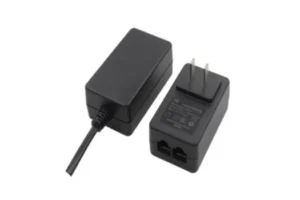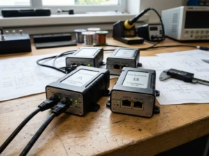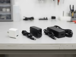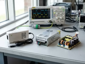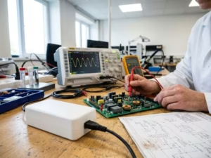

For an OEM network product, a PoE Adapter is not simply a wall plug with a wattage printed on it. It links AC input, PoE negotiation, Ethernet data, the enclosure and the certification plan. We select one by proving these interfaces work together under real operating conditions.
This guide explains the checks we use before an RFQ: translating the device specification, separating PoE compatibility from Ethernet speed, testing thermal and EMC behavior in the final enclosure, and requesting evidence before approving a production source.
1. Start with the device contract, not the adapter label
We begin with a one-page “device contract.” It captures the conditions the powered device (PD) will impose on the power source:
| Requirement | What we record before model selection |
| DC voltage | Nominal voltage, tolerance and any startup or brownout limits |
| Power | Continuous load, peak/startup load and allowed power margin |
| PoE behavior | IEEE standard, class, negotiation method and restart behavior |
| Data path | 10/100 Mbps, 1G, 2.5G, 5G or 10G requirement, plus cable category |
| Environment | Ambient range, enclosure volume, airflow, altitude and duty cycle |
| Interfaces | RJ45 pin definition, DC connector, cable length, shielding and grounding |
| Market access | Required safety, EMC and regional marks for the product’s destination |
This avoids a common sourcing error: choosing a 48V or 54V unit while overlooking active negotiation, startup surge or connector pinout. Two products can show the same voltage and still behave differently when the PD requests power. We review the adapter and device as one electrical system.
For the first power estimate, we use I = P / V and distinguish rated output from the power that reaches the device after conversion and cable losses. We add margin based on measured startup demand, duty and thermal derating—not a universal percentage. An always-on access point in a sealed box needs a different margin from an intermittently used POS terminal.
2. Match the IEEE PoE standard and the data path separately
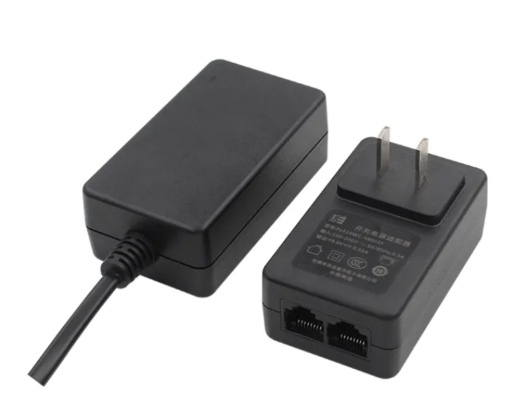
IEEE 802.3af, 802.3at and 802.3bt describe different power-delivery envelopes and negotiation behavior. In practice, we map them to the device requirement as follows:
| Standard family | Typical design question | Evidence to request |
| 802.3af | Is the endpoint a lower-power phone, sensor or camera? | PD classification and interoperability result |
| 802.3at (PoE+) | Does the endpoint need more power for radios, displays or peripherals? | Type/class behavior at the required load |
| 802.3bt (PoE++/four-pair) | Does the product need a higher power budget or four-pair delivery? | Four-pair test coverage and the exact Type supported |
The standard is only one half of the interface. Ethernet speed must be checked on the same model and SKU. A portfolio may contain 10/100Mbps, 1G, 2.5G, 5G and 10G options, but a 100W rating does not automatically imply 10G operation. We confirm the advertised speed with the exact RJ45 configuration, cable and magnetics used in the customer’s equipment. For background on standard-based interoperability and test plans, see the Ethernet Alliance PoE Certification program.
We also ask whether the application expects active PoE negotiation. A passive feed can look correct on a bench and still fail with a PD that waits for detection and classification, so this check belongs in bring-up.
3. Use the published power range as a starting point
Our current PoE portfolio gives an OEM several starting points, but the final choice remains SKU- and application-specific. The PoE Adapter product series lists these families:
| Family | Published output | Where we usually start | What we verify before approval |
| PoE24 | 24W | IP phones and compact endpoints | Device class, 10/100Mbps requirement and startup current |
| PoE35 | 35W | IP phones, wireless APs and POS devices | Output window, connector definition and required Ethernet option |
| PoE54DZ | 54W | Gigabit APs, POS and Ethernet terminals | Sustained load, enclosure temperature and cable loss |
| PoE90 | 90W | Higher-power network equipment | 802.3bt behavior, thermal headroom and protection response |
| PoE100-54A | 100W | High-performance or industrial network equipment | Rated output, four-pair compatibility and EMC |
For example, the published PoE35-XXXYYYSPA model is a 35W AC-DC PoE Adapter with 90–264VAC input, 48–56VDC output, average efficiency of at least 85%, 802.3af/at support and 6kV surge immunity. Its product evidence also lists multiple Ethernet options by configuration. We treat the suffix and the delivered test report as part of the model identity; if a project needs 2.5G, 5G or 10G, that option must be written into the purchase specification rather than assumed from the family name.
4. Test thermal headroom in the final enclosure
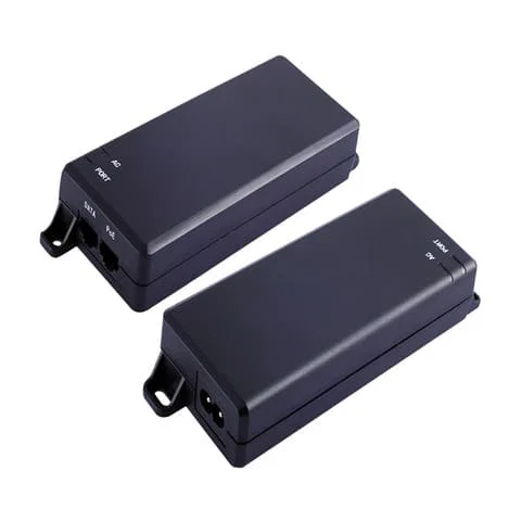
An adapter that passes an open-bench test can run hotter beside a radio, processor or battery. Our PoE thermal design review starts with the mechanical drawing, not a generic room-temperature efficiency number.
Our validation matrix includes:
- Minimum and maximum AC input at continuous rated load.
- Startup, restart and brownout recovery at the highest expected load.
- The customer’s actual enclosure, cable routing and airflow restrictions.
- Hot and cold ambient points, with temperatures measured at critical components and connector surfaces.
- Short-circuit, over-current and over-voltage response; over-temperature protection where the selected model includes it.
- Long-duration operation to expose drift in output voltage, ripple or Ethernet stability.
The published PoE options include 90–264VAC and, on selected configurations, 90–290VAC. We quote the exact range for the selected SKU rather than generalizing a category value. A 6kV surge figure is meaningful only when the test setup, coupling method and pass criteria are documented.
5. Make EMC and certification project gates
The PoE Adapter is part of the finished network product, so its switching noise, cable common-mode current and grounding scheme can influence the system EMC result. We put pre-compliance testing before the enclosure is frozen. If a late EMC change requires a different adapter, the mechanical fit, safety file and production schedule may all move.
For a US launch, the RFQ should state whether cULus/UL, FCC, CB or another mark is required for the exact adapter. We publish CE, CB, UL, CCC, PSE and KC at category level, while individual models can carry a different set of marks. We ask for the certificate, report number, revision and covered model suffix instead of accepting a family-level logo list.
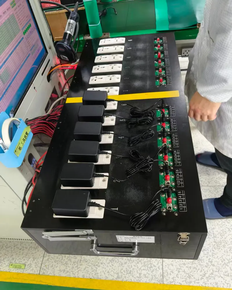
Our engineering workflow separates design verification from production release. Electrical review, schematic and fit checks, EMC pre-testing and EVT/DVT/PVT gates create a traceable record before tooling. In production, AOI, ICT, aging or burn-in, high-voltage insulation and load tests are linked to batch records through MES/SAP traceability. This shows how the approved sample will be reproduced.
6. Freeze mechanical and interface details early
Most late changes are mechanical or interface changes, not wattage changes. Before releasing a drawing, we confirm:
- RJ45 orientation, shield termination and the required pin definition;
- DC connector type, polarity, cable length, wire gauge and bend radius;
- enclosure dimensions, mounting method, creepage/clearance and airflow path;
- label content, regulatory marks, serial-number format and packaging;
- grounding and shielding strategy for the complete equipment assembly.
If a standard unit cannot fit, we can adjust output voltage/current, power and efficiency targets, RJ45/DC connectors, cable, dimensions, pin definitions and installation requirements. The custom power adapter development service is most effective when these constraints arrive with the first RFQ, before the customer’s enclosure or tooling is locked.
7. A procurement scorecard that protects the launch schedule
We recommend scoring each candidate against acceptance evidence, not marketing adjectives:
| Gate | Minimum evidence for a serious quotation |
| Electrical | Datasheet, tolerance, startup waveform, efficiency and derating curve |
| PoE interoperability | Standard/type, detection and classification behavior, PD test setup |
| Data | Verified Ethernet speed for the exact SKU, RJ45 and cable configuration |
| Thermal | Hot-spot data in the customer enclosure at rated load |
| EMC/safety | Applicable reports and certificates tied to the model suffix |
| Mechanical | Controlled drawing, connector pinout, cable and labeling files |
| Production | Sample-to-mass-production control plan, inspection and traceability method |
| Supply | Sample timing, forecast, lifecycle expectations and change-notification process |
This scorecard lets engineering and purchasing make the same decision and creates a clean handoff from prototype approval to volume production. The approved electrical, mechanical and compliance configuration becomes the reference for later shipments.
8. Build the PoE power budget with a worked example
Power budgeting becomes clearer when the numbers are separated into stages. Consider an industrial Ethernet terminal whose electronics consume 42W during normal operation and 50W for 200 milliseconds during startup. The design team also expects a long cable run and an enclosure that can reach 40°C ambient.
We would record three limits instead of writing “50W PoE” on the RFQ:
- PD load:42W continuous and 50W startup at the device input.
- Delivery loss:conversion loss inside the adapter plus voltage drop in the Ethernet and DC paths.
- Thermal derating:the output capability that remains at 40°C in the specified enclosure.
The adapter must pass the startup event without triggering over-current protection, then operate continuously below its derated limit. If the selected output is 54V, the continuous current for a 42W load is approximately 0.78A (42 / 54). That calculation is only a first check; it does not replace a measured waveform at the connector or a cable-loss calculation at the specified length.
For a second example, a compact access point may draw 18W continuously but reboot during a radio calibration event. We would test the calibration profile, not just the average power reported by a bench supply. The test report should show input voltage, output voltage, current, temperature and the event timeline so that the purchasing team can compare suppliers on the same basis.
This method also clarifies when a 90W or 100W model is justified. The decision is based on peak demand, derating, installation temperature and future hardware revisions—not on the assumption that a larger number is automatically more reliable. A documented budget reduces over-specification, thermal surprises and late changes to the power architecture.

9. Validate the adapter in the application that will ship
The same PoE Adapter can face very different risks in different products. We use an application-specific validation plan rather than one generic pass/fail test.
| Application | Primary risk | Additional validation we recommend |
| IP phone or video terminal | Startup and audio/video resets | Repeated boot cycles, standby-to-active transitions and cable hot-plug checks |
| Wireless access point | Radio bursts and enclosure heat | Maximum transmit profile, thermal mapping near the radio and long-duration throughput |
| Security camera | Outdoor transients and image dropouts | Surge condition, IR/night-mode transition and restart after a fault |
| POS or payment terminal | Peripheral peaks and uptime | Scanner/printer/display combinations, brownout recovery and connector retention |
| Industrial IoT gateway | Temperature, vibration and long duty cycle | Hot/cold starts, vibration exposure, shield/ground review and extended burn-in |
For an IP camera, for instance, the current draw can change when infrared illumination turns on. For a wireless access point, the highest heat may occur during sustained radio traffic rather than during an idle power test. For industrial equipment, the adapter may be mounted beside a drive or relay that adds conducted noise. Capturing these conditions before certification gives the compliance laboratory a stable configuration to test.
We also test the complete Ethernet path. The adapter, cable, coupler, magnetics and PD connector form one channel. A link that negotiates at 1G on a short lab cable may behave differently at the customer’s cable length or with a shield termination that was changed during mechanical integration. Recording link speed, packet error behavior and power delivery in the same test run makes these interactions visible.
10. Plan lifecycle, change control and serviceability
An OEM purchase is usually a multi-year decision. Even when the first build is small, the adapter may be installed in thousands of devices that are difficult to service in the field. We therefore include lifecycle questions in the first quotation:
- What is the expected production period and forecast profile?
- Which components are approved alternates, and which require customer approval?
- How will firmware-free electrical changes, connector changes or label revisions be notified?
- Can the supplier reproduce the approved sample after a factory move or component substitution?
- What serial, lot or date information is available for a returned unit?
We keep the approved model suffix, drawing revision, test limits and certification evidence together. Any proposed change is reviewed for electrical, thermal, EMC, safety and mechanical impact before release. Batch traceability through MES/SAP helps connect a shipment to its inspection record, while a defined change-notification process helps the OEM decide whether a re-test or filing update is needed.
Serviceability is also part of design. Clear labeling, accessible connectors and a predictable restart response can shorten field diagnosis. If an adapter is integrated inside a sealed product, the service plan may depend on replacing the complete equipment rather than the power module; that decision should be reflected in thermal margin and expected operating life.
11. Move from samples to production without losing the specification
We treat sample approval as a controlled baseline, not a one-time demonstration. The sample record includes the exact electrical configuration, enclosure interface, cable and connector, test conditions, measured results and approved artwork. A production order references that baseline so that “same model” means the same functional configuration.
Before volume release, we review:
- The golden sample and its serialized test data.
- The production bill of materials and approved component alternates.
- Inspection points for input/output, protection response, PoE behavior and appearance.
- Packaging and labeling for the destination market.
- The escalation path for nonconforming units and engineering changes.
This handoff is important for B2B buyers because the lowest unit price at prototype stage does not guarantee the lowest total cost. A stable source reduces requalification, field returns, certification rework and line stoppages. It also gives purchasing a factual basis for comparing offers instead of comparing only the headline wattage.
12. A concise RFQ template for a PoE Adapter project
To make technical review faster, we suggest sending the following information in one controlled file. Start with the device name, revision and intended US market. Add the input voltage and frequency, required DC voltage, continuous and peak power, startup profile, and whether the device expects active detection and classification. State the required IEEE 802.3af, 802.3at or 802.3bt type, Ethernet speed, cable category and maximum cable length.
Then provide the mechanical envelope: maximum adapter dimensions, mounting orientation, connector drawings, pin definitions, cable length, bend radius, shielding and grounding requirements. Include the ambient temperature, airflow restrictions, altitude, vibration or surge conditions and duty cycle. Finally, list required safety and EMC marks, annual volume, pilot quantity, target production date, expected lifecycle and packaging or labeling needs.
This format prevents an RFQ from becoming a series of disconnected email answers. It lets us identify missing information early, recommend a standard model where appropriate, or define a PoE ODM work package when customization is required. It also gives both sides a clear reference for sample approval, certification testing and repeat orders.
Frequently asked questions
Is a higher-wattage PoE Adapter always safer?
No. A higher rating can add thermal and cost overhead without solving a negotiation, pinout or EMC problem. We select the smallest rating that covers measured demand with a documented margin and derating profile.
Why will a device not start even though the adapter says 48V?
Check active detection/classification, IEEE type, output tolerance under startup, connector polarity and the RJ45 pin definition. Voltage printed on the label is not proof of interoperability.
Does 10G Ethernet require a 100W adapter?
No. Data speed and power rating are separate selection axes. We verify the exact model’s Ethernet capability and then size power for the device load, cable loss and thermal environment.
When should we request a custom design?
Request a PoE ODM review when the enclosure, connector, pin definition, cable, output or certification plan cannot be met by one standard SKU. Early review usually costs less schedule risk than changing a tooled enclosure later.
What should we send with an RFQ?
Send the device power profile, PoE standard/type, Ethernet speed, input range, ambient and enclosure data, connector drawings, target market marks, annual volume and lifecycle. With that package, we can return a model recommendation and verification plan instead of a wattage-only quotation.
A practical next step for your PoE program
At Quankang, we approach a PoE Adapter as a verified subsystem: the electrical specification, Ethernet behavior, thermal design, EMC evidence and production controls are reviewed together. Our manufacturing operation has operated since 1989 and is supported by in-house testing, documented development gates and batch traceability. When you share your device contract and RFQ data, our engineering team can help you move from a standard 24–100W starting point to a configuration that is ready for US certification and long-term supply. Contact our team for a quotation.