The power supply rarely gets the most attention in a medical device design. It should. Leakage current that exceeds limits, conducted emissions that fail by 3 dB, or a monitor that reboots during a voltage dip can each add months to a program. Most of these failures trace back to a power specification written as if the product were ordinary electronics.
This guide explains the requirements that actually matter, and why they exist. It is written for engineers defining the power architecture, product managers who own certification timelines, and procurement teams comparing suppliers. It covers:
- Isolation levels (MOOP/MOPP) and leakage current limits by applied part type
- Electrical performance, EMC, and thermal requirements
- Backup power, common specification mistakes, and a procurement checklist
Why Medical Power Supplies Face Stricter Requirements
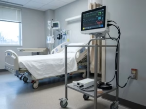
The rules are tighter because the risks are different. Standard IT equipment protects a user who is awake, dry, and able to let go. A medical device may be connected directly to a patient who can do none of those things.
Three conditions drive the gap:
- Conductive contact. ECG electrodes, catheters, and gel pads lower skin resistance, so the same fault current does more harm.
- Reduced self-protection. A sedated or unconscious patient cannot feel a shock or pull away.
- Functional dependency. If an infusion pump or ventilator loses power, the patient can be harmed even when no electrical fault occurs.
IEC 60601-1 handles these risks through two concepts used throughout this article. The first is single fault condition (SFC): the device must stay safe even after one protective measure fails, such as an open ground wire or a shorted insulation layer. The second is essential performance: the clinical functions that must keep working within defined limits, such as delivering the set infusion rate. Your power supply has to support both.
Dimension | IEC 62368-1 (ITE/AV) | IEC 60601-1 (Medical) |
|---|---|---|
Who is protected | Users and service staff | Operators and patients |
Isolation framework | Basic/reinforced safeguards | MOOP and MOPP, with MOPP more conservative |
Touch current limit (normal condition) | Up to 0.25 mA (Class II) / 3.5 mA (Class I) | 100 µA |
Patient leakage | Not addressed | As low as 10 µA (Type CF) |
That last row is why an off-the-shelf adapter can work perfectly on the bench and still fail certification.
How a Medical Power Supply Architecture Works
The simplest way to understand medical power requirements is to follow the energy path and see which requirement each stage controls. A typical AC-powered device moves energy like this:
AC input → EMI filter and rectifier → PFC → isolated DC-DC → secondary regulation → load and/or battery
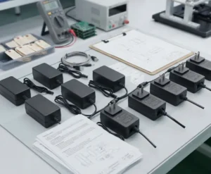
This architecture can live inside the device or in an external power supply (EPS). An EPS keeps high voltage out of the product enclosure and can simplify certification. An internal supply gives more control over thermal design and EMC layout.
Input filter and rectifier
This stage drives most of your conducted emissions performance and most of your earth leakage current. Y-capacitors connected from line to ground form the primary leakage path. Every conflict between EMC and patient safety starts here.
Power factor correction (PFC)
Above 75 W input, IEC 61000-3-2 harmonic limits usually require active PFC. The PFC stage sets the input current waveform and has a large effect on inrush current and hold-up capacitor sizing.
Isolated DC-DC converter
The transformer and its insulation system form the barrier between mains and everything the operator or patient can touch. Creepage, clearance, and dielectric withstand ratings are set at this stage, and they determine whether the supply can claim 1 or 2 MOPP.
Secondary regulation and outputs
This stage determines voltage accuracy, ripple, transient response, and how cleanly the supply interacts with sensitive analog front ends. If the device includes a battery, the charger and power-path switching also sit here.
Each section below maps to one or more of these stages.
Isolation and Leakage Current Requirements
Isolation and leakage are the core of medical power design — and the requirements most often misunderstood.
MOOP vs. MOPP: what the ratings actually mean
IEC 60601-1 defines two types of protection. Means of Operator Protection (MOOP) protects people who use the device but are not in contact with it. Means of Patient Protection (MOPP) protects the patient, using wider spacing and higher test voltages.
Rating | Dielectric test (AC) | Creepage* | Clearance* |
|---|---|---|---|
1 × MOOP | 1,500 V | 2.5 mm | 2.0 mm |
2 × MOOP | 3,000 V | 5.0 mm | 4.0 mm |
1 × MOPP | 1,500 V | 4.0 mm | 2.5 mm |
2 × MOPP | 4,000 V | 8.0 mm | 5.0 mm |
Typical values for 250 VAC working voltage at altitudes up to 2,000 m.
The practical rule: if any part of the device can touch a patient, specify a supply with 2 × MOPP from primary to secondary. A 2 × MOOP supply may be acceptable for equipment with no patient contact, such as a lab analyzer. But specifying 2 × MOPP from the start keeps your platform usable if the product later gains a patient-contact accessory.
Applied part types: B, BF, and CF
An applied part is any part of the device that contacts the patient during normal use. Its classification determines how much current can flow through the patient:
- Type B (Body): May be connected to earth. Used for patient beds and some imaging tables.
- Type BF (Body Floating): Isolated from earth, with surface contact. Used for blood pressure cuffs, SpO2 sensors, and ultrasound probes.
- Type CF (Cardiac Floating): Isolated from earth and suitable for direct cardiac contact. Used for ECG and invasive pressure monitoring.
Leakage type (AC) | Type B | Type BF | Type CF |
|---|---|---|---|
Patient leakage, normal condition | 100 µA | 100 µA | 10 µA |
Patient leakage, single fault | 500 µA | 500 µA | 50 µA |
Mains on applied part | Not applicable | 5,000 µA | 50 µA |
The power supply alone rarely achieves BF or CF performance. Those ratings typically need a second isolation barrier at the patient front end — usually an isolated DC-DC module plus a digital isolator. The main supply provides the mains barrier; the front end provides the floating barrier.
Earth leakage and touch current
Separately from patient leakage, the standard limits earth leakage current to 5 mA in normal condition and 10 mA under single fault. It limits touch current to 100 µA normal and 500 µA under single fault. Medical-grade supplies often specify earth leakage below 100–300 µA so the full system stays within limits after you add your own filters and cable capacitance.
A common scenario: A design team builds a multi-parameter patient monitor with a CF-rated ECG input. Their internal supply measures 80 µA of touch current — it passes. They then add a ferrite and two Y-capacitors to fix a radiated emissions failure, and system leakage rises to 140 µA. The board now fails. The fix was not more filtering, but a supply with lower intrinsic leakage and better common-mode noise performance, so the design had headroom from the start.
Electrical Performance Requirements
A supply can pass every safety test and still degrade device performance. Electrical requirements should be driven by what the load actually needs, not by a supplier’s datasheet defaults.
Voltage accuracy and regulation. Most digital loads tolerate ±5%. Precision analog rails feeding ADCs or sensor excitation circuits often need ±1% or better across line and load conditions. If a rail sets a measurement reference, its drift becomes a measurement error.
Ripple and noise. Specify ripple in millivolts peak-to-peak, measured with a 20 MHz bandwidth limit, and state the measurement method. A typical medical supply specifies 1% of output voltage. A front end measuring microvolt-level ECG signals may need 10–20 mV ripple or a dedicated low-noise LDO after the main supply.
Switching frequency. This is frequently missing from specifications. Ultrasound systems can show visible image artifacts if switching harmonics fall inside the imaging band. For sensitive acquisition, specify a fixed switching frequency or a supply that can sync to an external clock.
Transient response. Motors in infusion pumps, blowers in ventilators, and print heads in analyzers create sharp load steps. Specify the maximum deviation and recovery time for a defined step — for example, 50% to 100% load at 1 A/µs, with deviation under 5%.
Peak power. Compressors and motors may need two to three times their average power for hundreds of milliseconds. Sizing for peak avoids running a continuous-rating supply into derating on every motor start.
Hold-up time and inrush. Hold-up time, typically 10–20 ms at full load, determines whether the device survives short voltage dips. Inrush current matters when multiple devices share one power strip or mobile cart.
Device type | Most critical electrical parameters |
|---|---|
Patient monitor | Low ripple, low noise on analog rails, hold-up time |
Infusion pump | Transient response, peak power for motor |
Ultrasound | Switching frequency control, ripple spectrum |
Ventilator | Peak power, hold-up, seamless battery switchover |
EMC/EMI Requirements
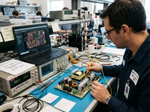
EMC is where medical power design becomes genuinely harder than the rest of the product. The governing standard is IEC 60601-1-2 (4th edition, with Amendment 1). It covers both how much noise the device emits and how much interference it can tolerate without losing essential performance.
The leakage-EMC trade-off
Y-capacitors are the cheapest way to suppress common-mode conducted emissions. They are also the main source of leakage current. A commercial supply can use several nanofarads of Y-capacitance. A medical supply often must manage with a fraction of that, relying instead on common-mode chokes, careful transformer shielding, and layout discipline. A supply with both low leakage and a strong emissions margin is the clearest sign of a mature medical design.
Emissions
Conducted and radiated emissions are tested to CISPR 11. Hospital devices may qualify for Class A. Devices used in the home must meet the stricter Class B limits. Ask suppliers for emissions data with margin — ideally 6 dB — because your enclosure, cables, and other circuits will consume part of that margin.
Immunity
Immunity levels depend on the intended use environment:
Test | Professional healthcare | Home healthcare |
|---|---|---|
ESD (IEC 61000-4-2) | ±8 kV contact / ±15 kV air | ±8 kV contact / ±15 kV air |
Radiated RF (IEC 61000-4-3) | 3 V/m | 10 V/m |
EFT/burst (IEC 61000-4-4) | ±2 kV | ±2 kV |
Surge (IEC 61000-4-5) | ±1 kV line-line / ±2 kV line-earth | ±1 kV line-line / ±2 kV line-earth |
Voltage dips (IEC 61000-4-11) | 0% for 0.5–1 cycle; 70% for 25/30 cycles; 0% for 250/300 cycles | Same |
The voltage dip test connects EMC directly back to electrical architecture. During a 0% dip lasting one cycle, the device must maintain essential performance — which depends on hold-up time. During a 250-cycle interruption, it depends on whether a battery is present. Many devices fail here not because of noise, but because nobody linked the dip requirement to the power design.
Thermal, Environmental and Lifetime Requirements
Most power supply field failures are thermal failures that develop gradually. Getting the operating environment right in the specification is the cheapest reliability decision you can make.
Derating and convection
Datasheet ratings typically assume 25–40°C ambient air with good airflow. Above that, supplies derate — commonly to 50% output at 70°C. The temperature that matters is the air inside your enclosure, which often runs 15–25°C above room temperature. A 150 W supply in a sealed enclosure with 60°C internal ambient may effectively deliver only 100 W.
Fans introduce another issue. In a bedroom, fan noise disrupts patient sleep. In home use, fans pull dust and debris into the device. Convection-cooled supplies cost more upfront but eliminate a moving part and a maintenance concern.
Capacitor life
Electrolytic capacitors typically limit the working life of a power supply. Their life roughly doubles for every 10°C drop in core temperature. A capacitor rated for 5,000 hours at 105°C, running at 65°C, lasts around 80,000 hours — roughly nine years of continuous use. Run it at 85°C and that drops to about 20,000 hours, or two years. Ask suppliers for capacitor temperature data at your operating conditions, not just MTBF figures.
Surface temperature
IEC 60601-1 limits the temperature of touchable surfaces and restricts applied parts in prolonged patient contact to 43°C. An external supply that might sit under a blanket during home use must stay within these limits under those conditions.
Use environment
Environment | Added standard | Power supply implications |
|---|---|---|
Hospital | IEC 60601-1 baseline | Stable mains, controlled climate, Class A emissions may be acceptable |
Home healthcare | IEC 60601-1-11 | Class B emissions, 10 V/m immunity, untrained users, wider storage range (often −25°C to +70°C) |
Emergency medical services | IEC 60601-1-12 | Vibration, shock, ingress protection, altitude up to 3,000 m or higher, vehicle DC input |
Altitude is easy to overlook. Insulation spacing in the base standard assumes operation up to 2,000 m. Air ambulance and high-altitude deployments require larger clearances. At 5,000 m the correction multiplier is approximately 1.48.
Backup Power Considerations
Backup power is part of essential performance, not an optional feature. The right question is not “how long will the battery last” but “what must keep working, for how long, and under what load conditions.”
Hospital power is not uninterrupted. In the U.S., NFPA 99 allows up to 10 seconds for generator transfer after a utility outage. A device with no internal power source will reboot during that window. For a ventilator or infusion pump, that is not acceptable.
Switchover must be seamless. The transition from mains to battery should produce no output dropout and no loss of settings. Test this under full load, including during a motor start.
Size the battery for end of life. Here is a worked example for a transport ventilator drawing 30 W average with a 4-hour runtime requirement:
- Energy needed: 30 W × 4 h = 120 Wh
- End-of-life capacity (80%): divide by 0.8
- Conversion efficiency (85%): divide by 0.85
- Cold-weather margin (10%): divide by 0.9
- Required nominal capacity: approximately 196 Wh
That number has a logistics consequence. Lithium batteries above 100 Wh need airline approval for passenger transport, and above 160 Wh they are generally not permitted in passenger cabins. For a device that travels with patients, this may require a dual-pack design.
Chemistry and compliance. Lithium-ion offers higher energy density; LiFePO4 offers more cycles and better thermal stability. Either way, cells and packs need IEC 62133-2 certification and UN 38.3 transport testing. Low-battery alarms must follow IEC 60601-1-8 requirements.
Common Specification Mistakes
These are the errors that appear most often in design reviews and supplier qualification processes.
Mistake #1: “An IEC 62368-1 certified supply is good enough.”
IEC 62368-1 does not address MOPP, patient leakage, or applied parts. Using a commercial supply means adding isolation and leakage controls elsewhere — which typically costs more than specifying a medical-rated supply from the start.
Mistake #2: “It’s rated 2 × MOPP, so leakage is covered.”
MOPP describes the insulation barrier strength. Leakage depends on capacitance across that barrier and in the filter network. A 2 × MOPP supply can still produce too much leakage for a CF-rated device.
Mistake #3: “A certified power supply makes the device compliant.”
The supply’s CB report is evidence for your technical file, not a substitute for system-level testing. Leakage, EMC, and temperature are all measured on the finished device.
Mistake #4: “We’ll fix EMC at the end.”
Late EMC fixes almost always add Y-capacitance or shielding — both of which affect leakage. Emissions margin needs to be part of the power architecture from the first prototype.
Mistake #5: “The datasheet rating is the usable rating.”
Usable power depends on internal ambient temperature, airflow, altitude, and input voltage. Calculate the derated power before selecting a supply size.
Procurement Checklist
Use this list to compare suppliers on equal terms. Any item a supplier cannot document is a risk you carry into certification.
- Safety certification: IEC 60601-1 CB report and certificate, with edition and amendment listed
- Isolation rating: 2 × MOPP primary to secondary (or a justified alternative), with test voltages
- Leakage data: Earth leakage and touch current measured at 264 VAC, normal and single fault conditions
- EMC data: Conducted and radiated emissions plots showing margin to CISPR 11 Class B
- Immunity: Test results to IEC 60601-1-2 4th edition, including voltage dips
- Electrical performance: Ripple measurement method, transient response, hold-up time, peak power rating
- Switching frequency: Fixed value or sync capability, if your device includes sensitive signal acquisition
- Thermal: Derating curve, capacitor temperatures at rated load, convection vs. forced air
- Environment: Rated altitude, storage temperature range, and applicability to IEC 60601-1-11 or -1-12
- Lifecycle: Change notification policy, last-time-buy terms, and expected product life
The final item matters more than it may appear. Medical devices often remain in production for 7–10 years, and an unannounced component change in a power supply can trigger retesting across multiple certifications.
Conclusion
Medical power supply requirements become manageable when you treat them as a connected system. Isolation sets the barrier. Leakage limits determine how much filtering you can use. Filtering sets your EMC margin. Hold-up and battery design decide whether essential performance survives a dip or outage. Thermal design determines whether all of it still works in year eight.
Start with three decisions before selecting any supply: define your applied part type, confirm your use environment, and calculate derated power using your real enclosure conditions — not datasheet numbers. Those three inputs narrow the field considerably and prevent the most common late-stage failures.
If you are evaluating medical power supplies for an upcoming design or qualification, the most useful thing to request from any supplier is not a product brochure — it is measured leakage and emissions data with actual margin figures. A supplier willing to share that before a purchase order is one worth talking to. You can also review how specific medical device applications map to different power supply form factors and certification paths, which can help narrow your specification earlier in the design process.
Frequently Asked Questions
How do I know if a supplier’s emissions and leakage data is reliable?
Ask for the actual test plots, not just a pass/fail summary. Emissions reports should show measured curves against the CISPR 11 limit line, with visible margin. Leakage data should include the input voltage and test conditions used — worst-case figures are measured at 264 VAC, not the nominal 230 V. If a supplier can only provide a certificate without the underlying test data, that is a meaningful signal. Suppliers with in-house EMC capability are generally able to share pre-compliance data alongside formal reports, which gives you a much clearer picture of real design headroom.
Can a supplier’s certified power supply make my device compliant?
No. A certified power supply supports your technical file, but it does not transfer compliance to the finished device. Leakage current, EMC emissions, and temperature rise are all measured at the system level — on your device, in your enclosure, with your cables attached. A supply that meets IEC 60601-1 on its own can still push a system over the leakage or emissions limit once it is integrated. Treat the supplier’s certification as a strong starting point, not a finish line.
Do I need 2 × MOPP even if my device doesn’t directly touch the patient?
Not always, but it depends on how your applied parts are classified and how the device may evolve. If no part of the device contacts the patient in normal use — a lab analyzer or imaging workstation, for example — 2 × MOOP may be sufficient. However, if there is any possibility the platform will later support a patient-contact accessory, specifying 2 × MOPP from the start avoids a costly redesign. When in doubt, the more conservative rating is almost always the lower-risk choice for certification.
What is the difference between a medical-grade power supply and a standard commercial one?
A medical-grade power supply is designed to meet IEC 60601-1, which sets stricter requirements than commercial standards like IEC 62368-1. The key differences are patient leakage current limits (as low as 10 µA for CF-type devices versus no requirement in commercial standards), reinforced isolation rated to 2 × MOPP, and mandatory safe operation under single fault conditions. A standard commercial supply may pass every test on its own datasheet and still fail medical certification at the system level.