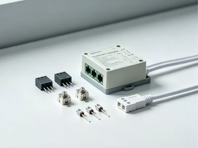
Power Supply Peripheral Design Series
A 65 W adapter passes every bench test, then fails at ±2 kV surge because the bulk capacitor took a hit the MOV didn’t stop. Another design passes surge, but after two years on a site with unstable mains, the MOV runs hot, shorts, and chars the PCB. A third fails Hipot because someone placed an MOV between line and protective earth. In each case, the engineer picked a part labeled “471K” and moved on.
MOV selection deserves more care than that. A metal oxide varistor (MOV) is a voltage-dependent resistor: near-open-circuit at normal line voltage, then conducting hard within nanoseconds when a surge arrives. This guide covers how to choose one for an AC power supply input stage, where most MOV mistakes happen.
You’ll learn:
- The five datasheet parameters that actually decide selection
- A six-step method with a worked 65 W example
- When to pair an MOV with a TVS diode or GDT
- How MOVs degrade and fail, and the mistakes that cause it
What an MOV Does in a Power Supply Input Stage
An MOV only makes sense once you see where it sits and what it protects. Every parameter in the next section ties back to this position.
Where the MOV Sits
In a typical offline power supply, the input stage looks like this:
AC input → fuse → MOV (L-N) → EMI filter → NTC → bridge rectifier → bulk capacitor
The MOV goes after the fuse for one specific reason. When an MOV reaches end of life, it usually fails short. The fuse is what disconnects the circuit when that happens. Put the MOV ahead of the fuse and a failed part becomes a direct short across the mains with nothing to clear it.
The MOV’s V-I curve is sharply nonlinear. Below its varistor voltage, it leaks only microamps. When a surge arrives, it clamps the voltage to a defined level. That word matters: clamp, not erase. Every downstream part still sees the clamping voltage, which is why the relationship between clamping voltage and downstream component ratings is so important.
L-N vs L-PE / N-PE Placement
An MOV across L-N handles differential-mode surges — the main threat for a 2-wire Class II adapter. Common-mode protection, from L-PE and N-PE, is a different problem entirely.
Placing a bare MOV from line to earth creates two problems:
- Leakage current. MOVs carry hundreds of picofarads of capacitance. A 14D part adds tens of microamps of earth leakage at 230 VAC — significant in low-leakage or Class II designs.
- Hipot failure. During dielectric strength testing, the MOV conducts and the test fails unless the part is disconnected.
That’s why common-mode positions typically use an MOV in series with a gas discharge tube (GDT). More on that in the comparison section below.
The Five Parameters That Decide MOV Selection
A part number like 14D471K encodes disc size (14 mm), varistor voltage (47 × 10¹ = 470 V), and tolerance (K = ±10%). But the part number alone won’t tell you whether the MOV fits your design. These five datasheet parameters will.
Maximum Continuous Operating Voltage (MCOV)
MCOV is the highest voltage the MOV can sustain indefinitely without heating up. Datasheets list both an AC rms value and a DC value. A 471K part is typically rated 300 VAC / 385 VDC. A 431K is typically 275 VAC / 350 VDC.
Selection rule: MCOV must exceed your maximum line voltage, including tolerance and expected abnormal overvoltage. This is the first filter. Any part that fails it is out.
Varistor Voltage (V1mA)
Varistor voltage is the voltage measured across the MOV at 1 mA DC — the “471” in the part number. With K tolerance, a 471K can measure anywhere from 423 V to 517 V.
V1mA is a characterization point, not an operating rating. The most common mistake is comparing it against line voltage instead of using MCOV. V1mA is most useful as a baseline for detecting aging later in the product’s life.
Clamping Voltage
Clamping voltage is the peak voltage across the MOV at a specified 8/20 µs test current. That test current varies with disc size: a 10D part is often specified at 25 A, while a 14D is specified at 50 A. A 14D471K typically clamps around 775 V.
Selection rule: Compare clamping voltage against the ratings of everything downstream — bridge rectifier, bulk capacitor, and primary MOSFET. If those ratings are lower, you need either a lower-voltage MOV, or test evidence that series impedance absorbs the gap.
Surge Current and Energy Rating
This parameter has three parts, and you need all three:
- Single-pulse peak current (8/20 µs). The maximum surge the MOV survives once.
- Energy rating (joules). Usually at 2 ms or 10/1000 µs, covering longer events.
- Pulse-life derating curve. Allowed current drops sharply as pulse count rises. A part rated 4,500 A for one pulse may only handle a few hundred amps over thousands of pulses.
The single-pulse rating is a ceiling, not a design target. Real selection uses the derating curve at the surge count your product will accumulate over its service life.
Disc Size
Disc size sets surge capacity, but it also affects capacitance, footprint, and cost. Larger discs handle more energy but add capacitance, which raises earth leakage and alters high-frequency behavior.
Disc size | Typical single 8/20 µs surge current | Clamping test current | Typical use |
|---|---|---|---|
7D | 1,200–1,750 A | 10 A | Low-power adapters, compact chargers |
10D | 2,500–3,500 A | 25 A | 30–100 W adapters, small appliances |
14D | 4,500–6,000 A | 50 A | 100 W+ supplies, outdoor or industrial input |
20D | 6,500–10,000 A | 100 A | High-exposure mains, lighting, SPD modules |
Values vary by manufacturer. Always confirm with the datasheet.
How to Choose an MOV: A Step-by-Step Method
Parameters only become useful when you run them in sequence. This method narrows the field quickly and catches conflicts before the first surge test.
Six Selection Steps
- Set the maximum line voltage. Include tolerance and target market. Universal input tops out at 264 VAC. Some U.S. commercial installations use 277 VAC, pushing you toward a 511K or 561K part. This sets your MCOV floor.
- Define the surge environment. Use the IEC 61000-4-5 test level for your product. L-L tests use a 2 Ω source impedance; L-PE tests use 12 Ω. Worst-case peak current is roughly 1 kV ÷ 2 Ω ≈ 500 A for L-L, or 2 kV ÷ 12 Ω ≈ 167 A for L-PE.
- Check clamping voltage against downstream ratings. Typical limits: 600–1,000 V for the bridge, 400–450 V for the bulk capacitor, 600–800 V for the MOSFET.
- Derate for pulse life. Estimate the total surges the product will see over its life and read the derating curve at that count.
- Pick the disc size. Balance surge capacity against board space, capacitance budget, and cost.
- Coordinate with the fuse. The fuse’s pulse I²t must survive the test surge without opening. It must also clear reliably if the MOV fails short. Estimate the surge I²t from the 8/20 µs waveform and keep margin for repeated pulses.
Worked Example: 65 W Universal-Input Adapter
Here’s the method applied to a Class II, 2-wire adapter targeting ±1 kV L-L surge.
Parameter | Value | Decision |
|---|---|---|
Input range | 90–264 VAC | MCOV must exceed 264 VAC with margin |
Candidate part | 471K (MCOV 300 VAC) | 13% headroom over 264 VAC, passes |
Surge level | ±1 kV L-L, 2 Ω | Worst-case 500 A |
Actual MOV current | ~110–150 A | Generator voltage minus clamp, divided by 2 Ω |
Disc size | 10D or 14D | Both capable; 10D sufficient unless pulse count is high |
Clamping voltage | ~775 V | Exceeds bulk capacitor rating — verify by test |
Two details deserve attention. First, the 500 A figure assumes a dead short. Once the MOV clamps near 700 V, the real current is closer to (1,000 − 720) ÷ 2 ≈ 140 A. That’s why 10D is often sufficient for this adapter class.
Second, 775 V looks alarming next to a 400 V bulk capacitor. In practice, the EMI choke, NTC, and trace impedance share the stress, and the capacitor’s own bulk absorbs much of the energy. But calculation alone doesn’t settle this. Probe the bulk capacitor voltage during the actual surge test and confirm it stays below its surge rating.
431K or 471K?
A 431K clamps lower, which helps downstream parts. But its 275 VAC MCOV leaves only about 4% margin at 264 VAC, so it ages faster on high-line or unstable grids. For universal-input designs where overvoltage robustness matters, choose 471K. Drop to 431K only when downstream voltage ratings are tight and testing confirms the trade-off is acceptable.
MOV vs TVS vs GDT: When an MOV Alone Is Not Enough
Each device solves a different problem. An MOV offers high energy absorption at low cost but degrades with repeated surges. A TVS diode clamps precisely and responds in picoseconds but handles little energy. A GDT carries huge peak current with almost no capacitance but responds slowly and can sustain follow current on AC mains.
Feature | MOV | TVS diode | GDT |
|---|---|---|---|
Response time | Nanoseconds | Picoseconds | Microseconds (voltage-dependent) |
Clamping precision | Moderate, rises steeply with current | Tight | Low — arc voltage after firing |
Energy capability | High | Low to moderate | Very high |
Capacitance / leakage | Hundreds of pF to nF | Tens to thousands of pF | Below 2 pF, near-zero leakage |
Aging | Degrades with each surge | Stable within ratings | Stable, slow wear |
Typical position | AC input L-N | DC output, low-voltage rails | L-PE / N-PE, often with an MOV |
Three combinations cover most power supply designs:
- MOV + GDT in series (L-PE, N-PE). The GDT blocks leakage and keeps Hipot clean. The MOV stops GDT follow current once the surge passes.
- TVS on the secondary DC output. Low-voltage rails need tight clamping that MOVs can’t deliver.
- Thermally protected MOV (TMOV) or a separate thermal fuse for high-exposure or unattended installations.
An MOV alone is enough when the threat is purely differential mode and the environment is mild — a Class II residential adapter with only L-N protection, for example. Once you add an earth conductor, high-exposure mains, or strict leakage limits, move to a combination. This is also worth revisiting if your design has overvoltage protection elsewhere in the circuit, since the two layers interact.
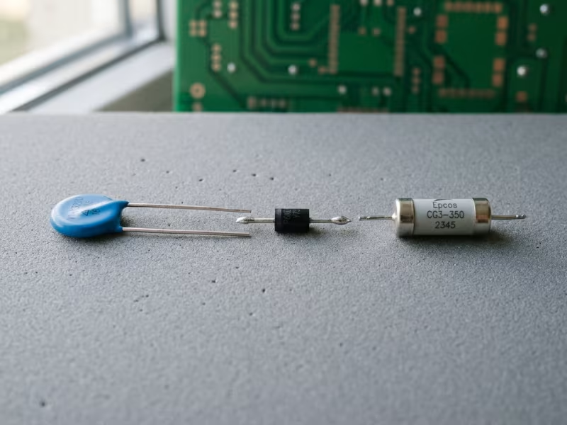
Degradation, Failure Modes, and Safety Coordination
Most MOV problems don’t surface during qualification. They appear in the field, years later. Every surge the MOV absorbs causes small microstructural changes. Over time, V1mA drifts and leakage current rises. The industry commonly treats a V1mA shift beyond ±10% as end of life — and there’s no visible warning before that point.
The most dangerous failure isn’t the surge itself. It’s sustained overvoltage: a lost neutral that places phase-to-phase voltage on a single-phase load. The MOV conducts continuously, heats, and enters thermal runaway. It typically fails short first, then may crack, smoke, or ignite. This is exactly the condition UL 1449 abnormal overvoltage testing is designed to catch.
Engineering note: A degraded MOV can look identical to a new one. Design for the failure mode, not just the surge event.
Three countermeasures address this:
- Fuse coordination. The fuse must clear a shorted MOV before it overheats.
- Thermal protection. Use a TMOV or place a thermal fuse in direct contact with the MOV body.
- Physical separation. Maintain spacing between the MOV and nearby components, and add a flame-retardant barrier where clearance is tight.
Prefer parts certified to IEC 61051 or carrying a UL recognition mark. Certification doesn’t prevent degradation, but it confirms the part behaves predictably when it does fail.
Common MOV Selection Mistakes
These five errors appear repeatedly in design reviews. Each maps directly to a step in the method above.
- Mistake: Using varistor voltage instead of MCOV.
Fix: Compare MCOV against maximum line voltage, including tolerance and abnormal overvoltage conditions. - Mistake: Sizing from the single-pulse surge rating.
Fix: Read the pulse-life derating curve at your expected surge count over the product’s service life. - Mistake: Choosing a low varistor voltage to get a lower clamp.
Fix: Accept a slightly higher clamp. A low V1mA accelerates aging and raises thermal runaway risk on high-line or unstable grids. - Mistake: Skipping fuse coordination.
Fix: Verify that the fuse I²t survives test surges without opening, and that it reliably clears a shorted MOV. Otherwise the fuse either nuisance-blows during testing or fails to protect in the field. - Mistake: Placing a bare MOV from L-PE.
Fix: Use an MOV + GDT series pair to control leakage and pass Hipot testing.
Conclusion
Good MOV selection comes down to three decisions. MCOV determines whether the MOV survives normal operation. Clamping voltage — matched against downstream component ratings — determines whether it actually protects anything. Derating, fuse coordination, and thermal protection determine whether it fails safely when it eventually wears out.
Start with your line voltage range and surge environment. Run the six-step method to narrow the part selection. Then validate by measuring bulk capacitor voltage during the actual surge test, because that measurement settles questions no datasheet can answer on its own.
If your project needs support on input protection layout, surge pre-testing, or integrating protection components into a custom power adapter or enclosure design, Quankang’s engineering team can help — including in-house EMC pre-compliance testing before formal certification.
Frequently Asked Questions
Should I use 431K or 471K for a universal-input power supply?
Choose 471K for most universal-input designs. Its 300 VAC MCOV gives meaningful margin at 264 VAC and during abnormal overvoltage events. Consider 431K only if downstream voltage ratings are genuinely tight and surge testing confirms the lower clamp is worth the reduced aging margin.
Can an MOV replace a TVS diode on the DC output?
Usually not. MOV clamping is too imprecise for low-voltage rails, and its aging behavior makes it a poor fit for secondary-side protection. Use a TVS diode on DC outputs.
How can I tell if an MOV has degraded?
Visual inspection rarely reveals it. Measure V1mA and check whether it has shifted more than 10% from its nominal value, or whether leakage current has risen noticeably. Equipment that has absorbed repeated surges should be included in periodic maintenance checks.