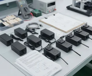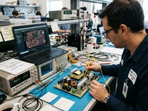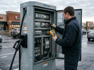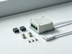
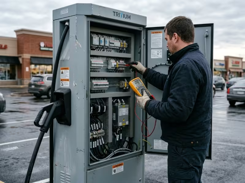
A 60 kW DC fast charger shows “offline” on the operator’s dashboard. The power modules are healthy. The cable and payment system are fine. The fault is a 150 W auxiliary supply — its electrolytic capacitors dried out after two summers in a sun-baked cabinet, or it absorbed one grid surge too many. The station earns nothing until a technician drives out with a replacement.
Auxiliary supplies get chosen late on most charger projects: picked from a catalog, by wattage, after the main power stage is already locked in. Yet they sit on the same grid, share the same cabinet heat, and are expected to last the same ten years. When one fails, the whole station goes dark.
A handful of clear criteria make the EV charging station power supply decision manageable. This guide covers:
- The power architecture inside AC and DC chargers
- How to size the auxiliary power budget
- Input range and surge requirements
- Cabinet environments and the standards that apply
- Reliability, form factors, and real lifetime cost
- A selection checklist and the mistakes that cause field failures
How Power Flows Through an EV Charging Station
Before you choose a supply, you need a clear map of the station. Every charger has two separate power paths with very different design rules.
Main Power Conversion vs. Auxiliary Power
The main power path carries energy to the vehicle. In an AC wallbox, it barely converts anything — the wallbox switches grid AC to the car through contactors, and the car’s onboard charger does the conversion. In a DC fast charger, the cabinet handles conversion itself, using stacked power modules, typically in the 20–40 kW class, to turn three-phase AC into high-voltage DC.
The auxiliary path powers everything that controls, protects, and communicates: the controller, touchscreen, modem, contactor coils, fans and pumps, energy meter, and safety monitoring. It draws a tiny fraction of the station’s power — but if it stops, the station stops. The rest of this article focuses on that auxiliary and control power.
The two charger types differ sharply in how much auxiliary power they need and where it lives:
Parameter | AC Wallbox | DC Fast Charger |
|---|---|---|
Grid input | Single- or three-phase | Three-phase |
Where AC-DC conversion happens | In the vehicle | In the charger |
Typical auxiliary load | Single-digit to tens of watts | Roughly 100 W to several hundred watts |
Typical auxiliary supply format | Board-mount module | DIN rail or enclosed supply |
Types of Power Supplies Inside a Charger
Most stations run on a layered set of supplies, not a single one. Logic runs at 3.3 V, contactors at 12 V or 24 V, and the pilot circuit needs a bipolar rail. Some circuits need isolation from others. Splitting supplies also contains faults: a problem in one load shouldn’t cascade into everything else.
Supply | What it powers | Key design concern |
|---|---|---|
Main AC-DC auxiliary supply (12 V or 24 V bus) | Controller, relays, contactor coils, fans, modem | Surviving grid surges, overvoltage, and cabinet heat |
Point-of-load DC-DC converters (5 V, 3.3 V) | MCU, memory, logic, display electronics | Low noise on logic and communication rails |
Isolated rails for control pilot and communications | ±12 V pilot circuit per IEC 61851-1, plus CAN, RS-485, and PLC interfaces | Isolation and accurate pilot signal levels |
IMD and safety-circuit supply (DC chargers) | Insulation monitoring device, emergency stop, safety relays | Staying powered during faults so protection still works |
Vehicle low-voltage auxiliary output (GB/T DC chargers) | 12 V (24 V on some vehicles) to the vehicle’s BMS during charging | Dedicated, current-limited, protected output |
Segregation is a fault-containment decision, not just a voltage convenience. A seized fan motor or shorted contactor coil shouldn’t reset the controller mid-session. Many DC designs feed fans and contactors from one rail and logic from another. Some add a redundant supply for safety-critical rails such as the insulation monitoring device (IMD), so a single supply failure can’t disable protection.
Sizing the Auxiliary Power Budget
Start from a full load inventory, not a guess carried over from the last project. Missed loads don’t show up on the bench — they show up on the first cold morning or the first heavy-use afternoon.
List every load and note how it behaves:
- Controller and touchscreen: a constant load. Screen and enclosure heaters in cold climates can exceed the display’s own draw.
- Communications: 4G/LTE modems, Ethernet switches, and PLC modems all draw short transmit peaks well above their average.
- Contactor and relay coils: pull-in current is several times higher than holding current. Large DC contactors are often the biggest peak on the bus.
- Fans, pumps, and heaters: inrush plus continuous load. Liquid-cooled cables on high-power chargers add a pump that runs through every session.
- Smaller loads that add up: RFID reader, energy meter, IMD, status lighting, and payment terminal.
Then apply a simple method:
- Sum all continuous loads under worst-case operation.
- Add the peaks that can occur together — contactor pull-in, fan start, modem transmit.
- Apply 20–30% headroom over the worst-case continuous load.
- Check the supply’s derated output at the maximum cabinet temperature, not its nameplate rating at 25 °C.
Step 4 is where most budgets fall apart. A 240 W supply that derates to 60% at 70 °C is effectively a 144 W supply inside a hot cabinet.
Typical ranges by charger class:
- AC wallbox (7–22 kW): a small board-mount supply in the single-digit to roughly 20 W range
- DC charger, 30–60 kW: an auxiliary budget of roughly 100–300 W
- High-power DC cabinet (150 kW and up): several hundred watts, often split across multiple supplies
Treat these as starting points, not specifications. Your load list sets the number. And resist simply going bigger — an oversized supply idles at light load around the clock, which adds real energy cost over a ten-year life.
Input Design: Surviving Real Grid Conditions
A laptop adapter sees a clean office outlet. A charger auxiliary supply sees a utility feed shared with megawatt-scale loads, long cable runs, and lightning-exposed overhead lines. Every input requirement below traces back to those conditions.
Input Range, Three-Phase Supply, and Neutral Loss
Single-phase auxiliary supplies are typically specified at 85–264 VAC, which covers normal grid tolerance. It doesn’t cover a lost neutral. In a three-phase installation, a broken or poorly terminated neutral lets the star point float. A supply wired line-to-neutral can then see voltage approaching line-to-line — about 400 VAC on a 230/400 V grid. A 264 VAC-rated supply won’t survive that for long.
Three practical options exist:
- Wide-input supplies rated to around 305 VAC. These give margin against sustained overvoltage, but stop short of full neutral-loss protection.
- Supplies wired line-to-line, or three-phase input supplies. These avoid the neutral entirely and survive the fault.
- Neutral-loss detection at the station level. This disconnects loads before damage occurs.
Some DC charger designs draw auxiliary power from the internal DC bus instead of the grid. The trade-off is straightforward:
- Benefit: the supply is shielded from grid transients by the power modules’ front end.
- Drawback: the supply loses power whenever the main stage shuts down, which complicates startup sequencing and can erase fault logs at exactly the moment you need them.
Surge, Overvoltage Category, and Insulation Coordination
Fixed, grid-connected chargers are typically installed at overvoltage category (OVC) III under IEC 60664-1. OVC describes how close equipment sits to the incoming supply, and therefore what transient it must withstand. For a 230/400 V system, OVC III means roughly 4 kV impulse withstand, versus 2.5 kV at OVC II. Many off-the-shelf ITE power supplies are rated only for OVC II — the datasheet headline specs won’t flag this, so check the CB report.
Surge immunity is tested to IEC 61000-4-5 at levels set by the charger’s EMC standard. Passing depends on coordination between the supply and the station’s surge protective device (SPD). An SPD clamps the surge but lets some voltage through; the supply must absorb the rest. Check three things:
- The supply’s own surge rating, line-to-line and line-to-earth
- The SPD’s let-through voltage compared against that rating
- Whether the supply restarts automatically after a surge, without a site visit
Outdoor and Cabinet Environments
The weather report doesn’t set your operating temperature — the cabinet does. Sun load, power-module heat, and sealed IP54 or IP55 construction can push internal air well above the outdoor ambient. Design to the measured internal temperature at full charging power on the hottest day you expect. If you don’t have measurements yet, get them from a prototype before finalizing the supply spec.
- Temperature range and derating: Outdoor chargers commonly require −30 °C or −40 °C to +70 °C. Read the derating curve above 50 °C, where most supplies begin losing output. Verify cold start at the minimum temperature — some supplies start slowly or not at all when their capacitors are cold.
- Moisture and condensation: Daily heating and cooling cycles pull humid air into the cabinet, which then condenses on cold surfaces overnight. Specify conformal coating and ask how the supply performs at 95% RH non-condensing. A small cabinet heater can keep internal surfaces above the dew point in humid climates.
- Cooling method: Fanless convection or conduction cooling removes a wear-out part and eliminates a dust ingress path. At higher auxiliary power, a fan may be unavoidable — plan for maintenance access and monitor fan status.
- Altitude and pollution degree: Standard insulation ratings assume 2,000 m or below. Above that altitude, clearances need correction. Dusty, industrial, or coastal sites may require pollution degree 3 spacing, which calls for larger creepage distances than the standard pollution degree 2.
Safety Standards and EMC Requirements
Charging stations are certified at the station level. The auxiliary supply is a component that must support that certification — its own certificate doesn’t prove station compliance. The right question is whether the supply’s certified conditions actually match how you plan to use it.
Standard | Scope | What it means for the auxiliary supply |
|---|---|---|
IEC 61851-1 | General requirements for conductive charging, including the control pilot | Pilot rail accuracy and safe behavior during faults |
IEC 61851-23 | DC charging stations, including insulation monitoring | IMD and safety circuits must stay powered during faults |
IEC 61851-21-2 | EMC for off-board charging equipment | Sets surge and emission levels the full station must meet |
UL 2594 / UL 2202 | North American AC EVSE / DC charging equipment | Check whether the supply is UL recognized for this use |
IEC 62368-1 | Common component certification for the supply itself | Confirm OVC, pollution degree, and ambient in the CB report |
GB/T 18487.1 | China’s conductive charging requirements | Defines the vehicle low-voltage auxiliary output |
Confirm the current edition of each standard for your target market. No single certificate covers every region.
A certified supply doesn’t guarantee a system-level EMC pass either. Power modules switching at tens of kilohertz, long cable runs, and the cabinet’s grounding scheme all change what the test lab measures. Ask suppliers for measured emission margins in each frequency band — not just a “pass” result — and run pre-compliance scans on the complete cabinet as early as you can.
Reliability, Lifetime, and Serviceability
Operators typically expect a charger to run for about ten years outdoors. Electrolytic capacitors usually set the supply’s real service life, and their life roughly halves for every 10 °C rise in operating temperature. Require 105 °C-rated capacitors and ask for a lifetime calculation at your actual cabinet temperature — not at 25 °C or 40 °C.
Treat MTBF (mean time between failures) figures carefully. They’re only comparable when the calculation method and reference temperature match. Telcordia SR-332 and MIL-HDBK-217F can produce figures two to three times apart for the same supply. A million-hour MTBF calculated at 25 °C says nothing useful about a supply running at 60 °C.
Serviceability determines how expensive a failure becomes in the field. Look for:
- DC OK or power-fail signal wired to the controller, so the back office detects the fault remotely
- Hold-up time long enough for the controller to log the event and open contactors safely
- DIN rail or plug-in mounting so a technician can swap the supply in minutes
- Redundant or ORing configurations for safety-critical rails
Confirm the supplier’s end-of-life notice period and change-notification policy before committing. A charger platform may stay in production for many years. Requalifying a mid-life replacement supply means new testing and possibly new certification — an avoidable cost if you ask the question early.
Choosing a Form Factor
The right form factor follows the charger type, the cabinet layout, and how technicians will service the station.
Form factor | Best fit | Trade-off |
|---|---|---|
Board-mount AC-DC | AC wallboxes | Smallest and lowest cost, but a failure means replacing the whole board |
DIN rail | DC charging cabinets | Fast to swap in the field, widely available with OVC III ratings, but uses rail space |
Enclosed | Higher auxiliary power budgets | Rugged and straightforward to mount, but may need fan cooling |
Open-frame | Custom integrated designs with controlled airflow | Compact and flexible, but relies on the cabinet for protection |
When no standard part covers your input range, output mix, and temperature profile together, a custom power adapter is often more cost-effective than stacking several catalog supplies.
What Auxiliary Power Really Costs
Chargers sit idle for much of the day, but the auxiliary supply never does. Every watt of continuous draw adds up to 8.76 kWh per year. A DC charger idling at 30 W uses about 263 kWh annually. Across a 500-station network over ten years, that’s roughly 1.3 million kWh — multiply by your energy tariff to see what standby efficiency is actually worth.
Field failures cost more. One failed supply means a technician visit, hours or days of downtime, lost charging sessions, and an unhappy site host. That bill typically exceeds the supply’s purchase price several times over. A modest premium for wider input, an OVC III rating, or longer capacitor life usually pays for itself after one avoided failure.
Spend where the risk is highest: surge rating, temperature rating, and lifetime. Don’t pay for wattage you won’t use. Oversizing raises the unit price and lowers light-load efficiency — and light load is exactly where a charger spends most of its operating life.
Selection Checklist and Common Design Mistakes
Work through these steps in order. Each one narrows your options before the next.
- Map every auxiliary load, including peaks and inrush.
- Define the input: phase configuration, neutral-loss case, and OVC.
- Set surge and EMC targets from the station standard.
- Measure or estimate the internal cabinet temperature, and apply derating.
- Choose the form factor and cooling method.
- Verify certifications and read the conditions stated in the CB report.
- Confirm the lifetime calculation, monitoring signals, and EOL policy.
These are the mistakes that cause the most field failures and certification delays:
- Using an OVC II indoor supply in a grid-connected outdoor cabinet
- Sizing by nameplate wattage at 25 °C instead of derated output at cabinet temperature
- Forgetting contactor pull-in and fan inrush in the power budget
- Ignoring the neutral-loss fault at three-phase sites
- Assuming a certified supply means the station will pass EMC
Frequently Asked Questions
What does the auxiliary power supply do in an EV charger?
It powers everything except the energy delivered to the car: controller, display, communications, contactors, cooling, metering, and safety monitoring. It also drives the circuits that open contactors safely during a fault. A well-specified auxiliary supply keeps control alive when something goes wrong, so the station shuts down cleanly rather than losing power mid-session.
Can I use a standard industrial or ITE power supply in an EV charger?
Sometimes — but check three things first. Is it rated for OVC III? Does its operating range cover your cabinet temperature? Do its certified conditions match your installation? Many ITE supplies are rated only for OVC II, with full-load output limited to 40–50 °C. Industrial DIN rail supplies with OVC III ratings and wide temperature ranges are usually a better starting point for outdoor charger applications.
What input voltage range should an EV charger auxiliary supply have?
Specify at least 85–264 VAC for single-phase connection. At three-phase sites where neutral loss is possible, go wider — toward 305 VAC — or use line-to-line input. Also check brownout behavior. The supply should shut down cleanly during sustained undervoltage and restart automatically when voltage recovers, without latching off and requiring a site visit to reset.
Is a DIN rail power supply suitable for DC fast chargers?
Yes — it’s the most common choice for DC charging cabinets. DIN rail supplies are easy to swap in the field, widely available with OVC III ratings and wide temperature ranges, and many include a DC OK relay contact for remote fault monitoring. For safety-critical rails, pair two units with a redundancy module so a single supply failure doesn’t take the station offline.
Specify the Supply That Keeps the Station Online
The auxiliary supply is one of the least expensive parts in a charging station. It’s also one of the most consequential. Specify it for the grid it connects to, the cabinet it lives in, and the decade it needs to survive. Wattage is the last question to answer, not the first.
If you’re specifying an auxiliary supply for a new charger platform, start with your load list, input configuration, and measured cabinet temperatures. Our engineering team can recommend a supply — standard or custom — based on your actual requirements. You can also explore how we support power design across EV charging and other demanding industrial applications.