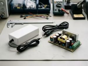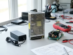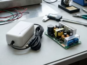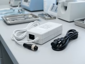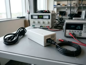
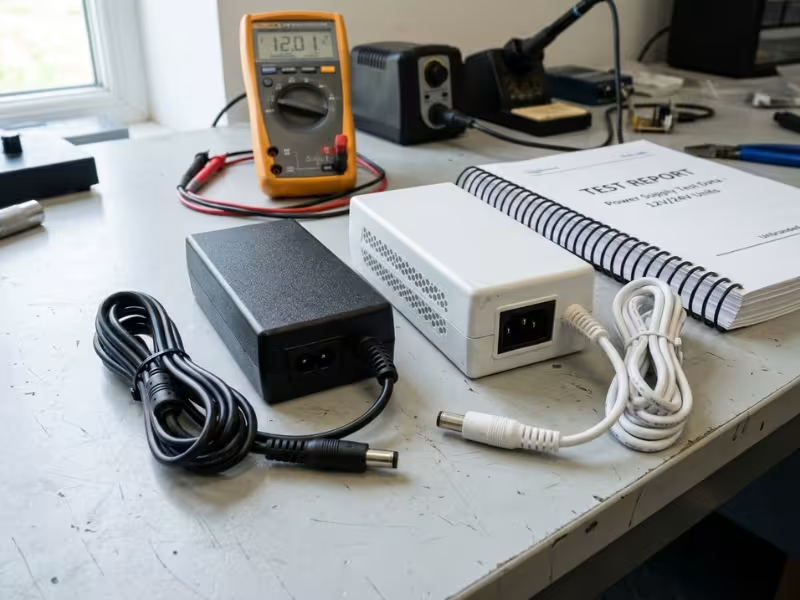
Two power supplies sit side by side on a quote. They have the same wattage, the same size, and the same connector. One costs twice as much and comes with a much thicker test report.
I work with engineering teams that choose power supplies for patient-connected devices. This price gap confuses them more than almost anything else on the BOM.
An ITE power supply is not a budget version of a medical power supply. The two protect different people from different risks.
This guide helps you decide which one your device needs. It also shows what a wrong choice costs in redesign, retesting, and launch delays.
The figures and examples below are practical reference points. Final requirements still depend on device classification, applied part type, system architecture, and the agreed test plan.
Why This Choice Can Delay Approval Even When the Device Works
A prototype can boot, measure, and display clean data on day one. That tells a reviewer almost nothing about patient safety.
FDA reviewers, EU notified bodies, and IEC 60601-1 test labs don’t ask whether your device works. They ask how it behaves when insulation breaks down, when the mains spikes, or when a nurse connects a second device to the same patient. Your power supply sits at the center of each of those questions.
The supply category shapes four things a reviewer checks closely:
- Leakage current. IEC 62368-1 allows touch current up to 0.5 mA for ordinary users. A CF applied part allows only 10 µA of patient leakage. An ITE supply can use up that entire budget by itself.
- Insulation path. A reinforced ITE barrier usually lands near 2 MOOP. A path to the patient usually drives a 2 MOPP design approach, which means wider creepage and a 4,000 Vac hipot test.
- EMC immunity. IEC 60601-1-2 checks whether your device keeps its essential performance during disturbances. ITE EMC data rarely answers that question.
- Submission evidence. Labs want a 60601-1 report for the supply. Without one, they test the supply inside your device, which adds time, cost, and risk.
Most delays I trace don’t start with a failed component. They start with a category error.
Here’s a pattern I see often. A team picks a quality ITE adapter for a device with BF applied parts, and every functional test passes. Then the lab measures leakage at 110% of rated voltage, and the numbers fail. The fix means a new supply, a fresh EMC run, an updated risk file, and new labels. That can add two to four months to the launch, and nothing ever “broke.”
ITE supplies still have a place. If your device has no applied parts, sits outside the patient environment, and only staff touch it, an ITE supply can be a sound choice. A lab analyzer or a staff-facing display often fits this case.
You still need the supply to meet the operator protection your device requires, and your risk file must explain the choice. Make that call on purpose, with evidence, rather than letting the price on a quote make it for you.
Start with the Real Question: Does Power Ever Reach the Patient?
Before you compare datasheets or prices, answer one question. Can any current from your device reach the patient, either directly, through a sensor, or through fluid?
That answer narrows your power supply choice faster than any spec sheet. I walk teams through three levels of contact. Each level raises the bar on leakage, insulation, and evidence.
No Patient Contact: Where ITE Can Work
Some devices never touch the patient. Lab analyzers, staff-facing displays, nurse station hubs, and many support carts fall here. A clinician operates them, and no part of the device connects to the patient’s body.
In these cases, an ITE power supply can be a sound choice. It depends on how you build the system, though.
Check two things first. If the device still counts as medical electrical equipment, its enclosure touch current must typically stay under 100 µA in normal condition. That limit is far tighter than the 0.5 mA many ITE supplies allow. Also check whether the device sits within about 1.5 m of the patient. If it does, your system design needs to account for that patient environment.
Some teams pick a medical supply here even when ITE would pass. A hospital customer may require IEC 60601-1 in its purchasing specs. A medical-rated supply can also shorten your test report and cut the documentation you need to defend the choice.
Patient Contact, But Not Cardiac: Where Type BF Raises the Bar
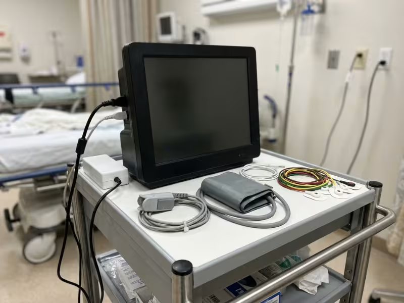
Once a part touches the patient, the rules change. Bedside monitors, exam devices, temperature probes, SpO2 clips, and blood pressure cuffs all fall here. Most of these parts are classified as Type BF, which means the patient connection must float from earth.
A floating connection needs a real isolation barrier, and the full path from mains to the patient usually needs 2 MOPP. You can meet that in two ways:
- Use a 2 MOPP medical supply. This is the cleanest path, and the supply’s report covers much of the evidence.
- Use a lower-rated supply and build full patient protection into an isolated front end. That barrier must then carry the MOPP rating by itself. Your team owns the design, the testing, and the paperwork.
The second route can work. In my experience, it rarely saves money once you count the extra lab time and documentation.
Cardiac or Higher-Risk Contact: Where Type CF Changes Everything
ECG leads, invasive blood pressure lines, and catheter-based sensors can create a path to the heart. These usually fall under Type CF, and many must also survive a defibrillator pulse.
CF limits patient leakage to 10 µA in normal condition. That’s one-tenth of the BF limit. At this level, small capacitances matter, because every picofarad across the patient barrier lets more mains-frequency current through.
Here’s a rough reference point. A 100 pF barrier passes about 10 µA at 264 V and 60 Hz. That alone can consume your entire CF budget. So CF designs typically need isolated DC/DC converters with very low coupling capacitance, defibrillation protection on every patient channel, and tight layout control.
In most practical designs, an ITE supply should not sit on the patient side of the protection path at this level.
Your Supply Choice Sets the Budget for Everything Else
Here’s the part most comparisons skip. Your power supply doesn’t just pass or fail its own leakage test. It decides how much leakage room the rest of your system gets.
Take a Class II bedside monitor with a 100 µA touch current limit. Suppose your supply uses 60 µA. That leaves 40 µA for everything else:
- Display and embedded PC: each often brings its own Y-capacitors
- EMI filter: line-to-earth capacitors can quietly eat 20 µA or more
- Isolated DC/DC for the patient front end: its barrier capacitance adds to the total
- Reserve margin: I hold back at least 20% for tolerance and late changes
With a low-leakage medical supply at 20 µA, you’d keep 80 µA for the same parts. That difference often decides whether you need a second filter redesign. So ask one practical question before you commit to a supply: after this supply takes its share, can the rest of my system still fit?
Why ISO 14971 Still Decides the Final Answer
These three contact levels give you a strong starting point. They don’t make the final call, though. Your risk management file does.
Applied part classification isn’t a marketing label you choose from a catalog. It follows the device’s intended use, where it contacts the patient, and what could go wrong. A finger clip used on a sedated ICU patient may raise different risks than the same clip in a clinic.
Your ISO 14971 file should show the reasoning behind your choice. List the hazards you considered, the contact paths you identified, and why your supply and isolation scheme control them. Reviewers read that logic closely. If your file says “ITE supply, no patient contact,” it needs evidence that no path exists, even under single fault conditions.
Make the classification first, write down why, and then pick the supply that fits it.
What Really Separates Medical from ITE Power Supplies
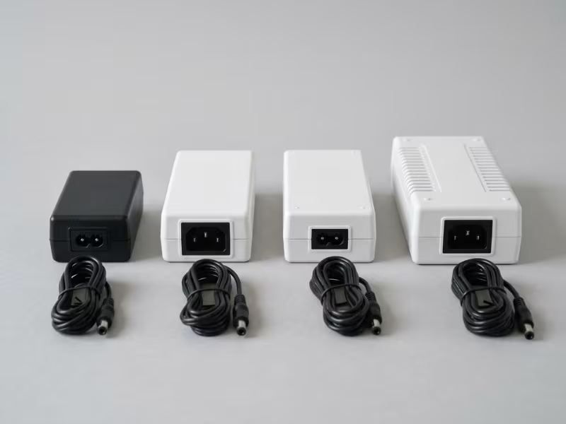
On a datasheet, an ITE supply and a medical supply can look nearly identical. They share the same wattage, the same output rail, and the same efficiency curve. The real differences show up in four areas, and each one affects your submission.
I compare them side by side below, because the contrast matters more than either definition alone.
Different Standards Ask for Different Proof
IEC 62368-1 governs ITE supplies. It is hazard-based. It classifies energy sources and asks whether safeguards keep that energy away from an ordinary person. It assumes that person can feel a shock and pull away.
IEC 60601-1 governs medical electrical equipment. It is risk-based and ties directly to your ISO 14971 file. It adds concepts that IEC 62368-1 never covers: applied parts, essential performance, and patients who can’t react.
That difference changes what a reviewer expects to see. An ITE report shows the supply is safe for an office worker. A 60601-1 report shows how the supply protects a patient, under both normal and single fault conditions.
Can a system-level evaluation cover the gap? Sometimes it can. IEC 60601-1 lets you use an ITE-certified supply when another barrier provides the required patient protection. One example is an isolated front end rated for 2 MOPP. Another is placing the supply outside the patient environment with proper separation.
It usually can’t cover the gap when the ITE supply forms part of the patient protection path. In that case, the lab must evaluate the supply’s construction against medical spacing and test voltages. Most ITE designs weren’t built to pass that review.
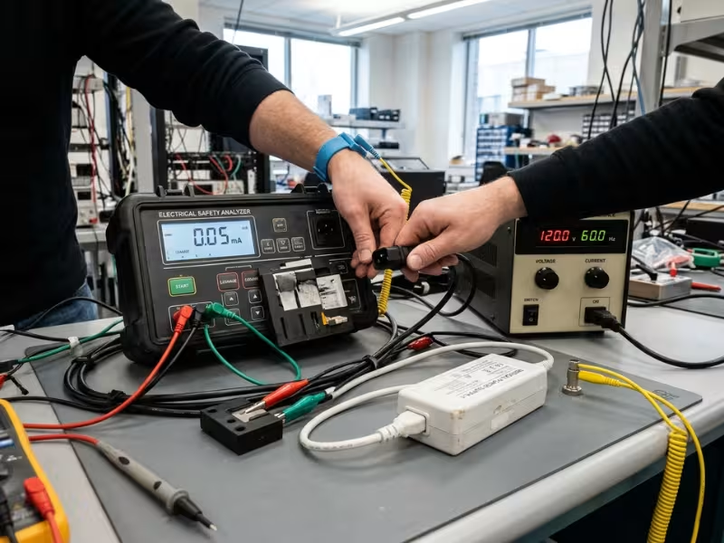
Leakage Limits Differ by a Factor of 50
This difference matters most in practice, and many teams underestimate it.
IEC 62368-1 allows touch current up to 0.5 mA for ordinary persons. IEC 60601-1 limits enclosure touch current to 100 µA in normal condition. For a Type CF applied part, patient leakage drops to 10 µA. That’s a 50-fold gap between an ITE touch limit and a CF patient limit.
The gap comes mostly from Y-capacitors. ITE designers use them generously because they make EMC easier, and the leakage limit leaves plenty of room. A typical Class II ITE adapter with a 2.2 nF Y-capacitor passes about 220 µA at 264 V and 60 Hz. That’s more than double the medical touch limit before you connect anything else.
So when you pick a supply, think beyond “does it pass?” Ask how much room it leaves for the rest of the system.
Here’s how I frame this for clients. Medical supplies often publish touch current figures under 75 µA, and some low-leakage models go below 10 µA. Each microamp the supply doesn’t use goes to your display, your EMI filter, and your patient isolation converter. An ITE supply can take your entire budget on day one, and every later filter tweak or added module then becomes a leakage problem.
Also check the test conditions. Labs measure at 110% of your highest rated voltage, and ITE datasheets often quote leakage at 115 V or 230 V. Ask for the figure at 264 V before you count on it.
Medical Insulation Is Wider, Thicker, and Hard to Add Later
ITE supplies protect operators. In medical terms, a well-built ITE barrier usually lands near 2 MOOP. Medical supplies intended for patient-connected devices typically carry 2 MOPP, which raises the bar in three places.
At a 250 V working voltage, 2 MOPP calls for about 8 mm of creepage and 5 mm of clearance. 2 MOOP calls for roughly 5 mm and 4 mm. The dielectric test also rises from about 3,000 Vac to 4,000 Vac. Above 2,000 m altitude, clearances grow further.
Those numbers reshape the hardware. A 2 MOPP supply needs a transformer built for 4,000 Vac, often with triple-insulated wire or extra margin tape. It also needs wide-body optocouplers, Y1-class capacitors, and routed slots in the PCB. You can’t add any of that to an existing ITE board.
That’s why retrofitting rarely goes smoothly. Teams usually try one of three fixes:
- An isolation transformer upstream. It adds weight, heat, and a new component to qualify.
- An isolated DC/DC converter downstream. It adds its own barrier capacitance, which feeds back into your leakage budget.
- Wider spacing on the main board. This usually means a new layout, a larger enclosure, and a new EMC run.
Each fix touches thermal design, EMC, and your risk file at the same time. I’ve seen teams spend more on a retrofit than a medical supply would have cost from the start.
Medical EMC Tests Performance, Not Just Survival
ITE EMC testing mostly asks whether the product stays within limits and recovers from disturbances. A brief reset or a flicker on screen is often acceptable.
IEC 60601-1-2 asks a harder question. Does the device keep its essential performance during the disturbance? For a patient monitor, that means no false alarms, no missed alarms, and no corrupted readings. A reset that an office printer could shrug off may count as a failure in a monitor.
The test levels are tougher too. Medical immunity testing typically applies ±8 kV contact and ±15 kV air discharge for ESD. It adds voltage dips at several phase angles and proximity fields from wireless devices up to 28 V/m. Home healthcare devices face 10 V/m radiated immunity, compared with 3 V/m in professional settings.
Your power supply sits at the front of all of this. Surges, dips, and fast transients enter through the mains input first. If the supply droops or passes noise to a sensitive front end, the device can lose essential performance even though nothing gets damaged.
So ask for 60601-1-2 data, not just CISPR 32 results. An ITE emissions report tells you little about how the supply behaves next to a patient.
Medical vs. ITE Power Supplies at a Glance
The earlier sections compared medical and ITE power supplies one difference at a time. Seeing them side by side makes the pattern easier to spot. I bring a version of this table to design reviews because it settles most supply debates quickly.
Treat the figures as practical reference points rather than final compliance limits. Spacing values assume a 250 V working voltage. Cost and lead time vary with wattage, volume, and supplier, so always confirm against the actual test report.
Power Supply Category | Main Standard | Typical Use Environment | Patient-Contact Suitability | Leakage Current Expectation | Insulation Expectation | EMC Path | Relative Cost / Lead Time | Best Fit Scenarios |
|---|---|---|---|---|---|---|---|---|
ITE power supply | IEC 62368-1 | Offices, labs, IT rooms, consumer settings | Not suitable as patient protection | Up to 0.5 mA touch current allowed; Class II models often run 100–250 µA | Reinforced insulation, roughly comparable to 2 MOOP | CISPR 32 emissions, CISPR 35 immunity | Baseline cost; often in stock or 2–4 weeks | Equipment outside medical scope, or supplies placed behind a separate MOPP-rated barrier |
Medical supply, 2 MOOP | IEC 60601-1 | Hospital areas where only staff touch the device | Operator protection only | Typically under 100 µA touch current in normal condition | ~5 mm creepage / ~4 mm clearance; 3,000 Vac hipot | IEC 60601-1-2, with CISPR 11 emissions and essential performance checks | About 1.2–1.5× ITE; 4–8 weeks | Lab analyzers, staff-facing displays, nurse station equipment |
Medical supply, 2 MOPP | IEC 60601-1 | Patient environment, bedside, exam rooms | Suitable for Type B and BF devices | Typically under 100 µA; many models under 75 µA | ~8 mm creepage / ~5 mm clearance; 4,000 Vac hipot | IEC 60601-1-2, professional or home healthcare levels | About 1.3–2× ITE; 4–8 weeks | Bedside monitors, SpO2 and BP devices, exam equipment |
Low-leakage medical supply, 2 MOPP | IEC 60601-1 | High-acuity care, ICU, OR, cardiac procedures | Supports Type CF designs when paired with a low-capacitance patient barrier | Often under 10–20 µA, which preserves the CF budget | 2 MOPP spacing plus very low coupling capacitance | IEC 60601-1-2, often with added margin for proximity fields | About 2–3× ITE; 8–12 weeks | ECG systems, invasive pressure monitoring, devices with several applied parts |
Cost climbs in steps rather than one big jump. A 2 MOOP medical supply often costs only a little more than a good ITE model, and it arrives with a 60601-1 report. For staff-facing hospital equipment, that small premium can shorten your submission and satisfy customer purchasing specs.
If you read only one column, read Patient-Contact Suitability. It decides whether the other columns even apply, because cost alone should not drive the choice when an ITE supply would sit on a patient protection path. Then check Leakage Current Expectation, since that number sets how much budget your display, filter, and isolated front end still have.
Common Mistakes Teams Make When They Try to Save Cost
Most power supply mistakes start as a sensible budget decision. A team sees a $15 gap per unit and looks for a way to close it. The savings show up on the BOM, while the costs show up months later in the lab.
These four shortcuts come up in almost every project review I join. Each one can work in a narrow case, so it helps to know where the line sits.
“ITE Is Cheaper, So We’ll Just Use It”
Sometimes this is the right call. An ITE supply can work when your device has no applied parts and sits outside the patient environment. It can also work when a separate barrier provides the full MOPP rating, such as a properly isolated patient front end.
Problems start when the ITE supply quietly becomes part of the patient protection path. Reviewers will then ask for medical spacing, a 4,000 Vac hipot, and leakage data at 110% of rated voltage. Most ITE designs can’t produce that evidence.
Before you sign off, trace the path from mains to every patient connection. If the ITE supply sits on that path with nothing rated MOPP after it, expect the lab to flag it.
“We Can Add Isolation Later”
Isolation behaves like a structural part of the design, not an accessory you bolt on. Once you decide to add it late, the change spreads to five areas at once:
- Layout: 2 MOPP needs about 8 mm of creepage, which often forces PCB slots and a larger board.
- Spacing: Connectors, heatsinks, and enclosure walls may need to move to keep clearances.
- Thermal: An extra isolated converter adds heat, often in a sealed case with no spare airflow.
- EMC: The new barrier changes noise paths, so your previous EMC results no longer apply.
- Documentation: Your insulation diagram, risk file, and critical components list all need updates.
I’ve seen a “small” isolation fix turn into a board spin, a new enclosure tool, and a second EMC campaign. If you think you might need isolation, design it in from the first schematic. Removing it later costs far less than adding it.
“The Device Only Touches the Patient Briefly”
This argument sounds reasonable, but contact time doesn’t decide applied part classification. IEC 60601-1 looks at whether a part must touch the patient during normal use. A probe held for three seconds still counts as an applied part.
A fault can also reach the patient in milliseconds. A short contact gives you no protection against a shock at the moment insulation fails.
Duration does matter in one place: surface temperature limits for applied parts depend on how long the part touches the skin. It doesn’t loosen your leakage limits, your MOPP requirement, or your BF or CF rating. So classify the part by what it touches, not by how long it touches it.
“Medical Power Supplies Are Always Too Expensive”
That belief comes from a time when medical supplies were niche products. Today, the market includes plenty of mid-range options. A 2 MOOP medical supply often costs only about 1.2 to 1.5 times a comparable ITE model. Many 2 MOPP adapters in the 30 W to 100 W range sit well within normal product budgets.
The bigger savings often come from the project, not the part. A pre-certified module with a full 60601-1 CB report can cut lab time, reduce questions from the lab, and keep the supply off your critical path. One avoided retest can easily cost more than the price premium on several thousand units.
Run the comparison on total project cost. Include lab fees, engineering hours, schedule risk, and possible redesign. The cheaper supply on paper often turns out to be the expensive choice once you add up the full path to approval.
How to Make the Decision Before You Order a Supply
Most supply mistakes happen before anyone asks for a quote. A buyer copies a part number from a reference design, and the choice gets made without anyone deciding it. I’d rather your team spend one focused hour on five questions first.
Start with the questions. Then write down the answers, so your choice still makes sense to a reviewer months later.
Questions to Answer Internally
Work through these in order. Each answer narrows the options for the next one.
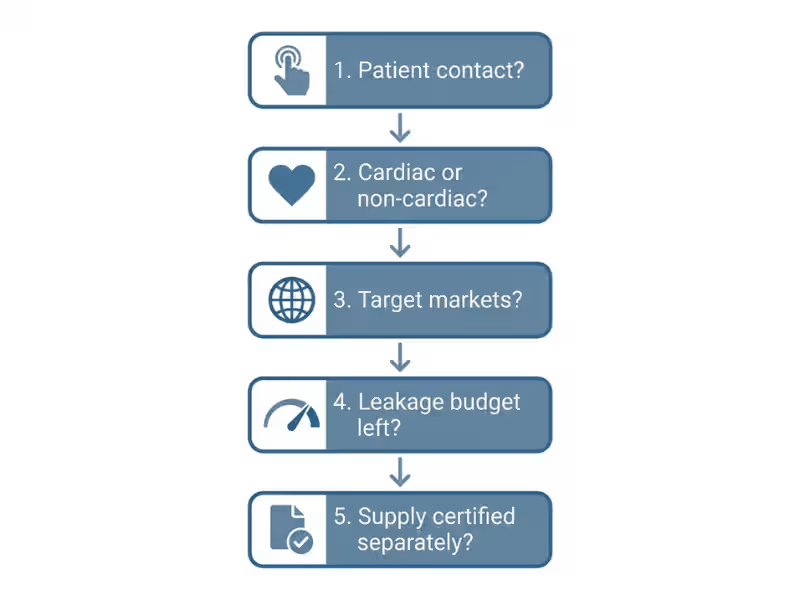
1. Does anything touch the patient directly or through fluid?
List every part that touches the patient during normal use. Include probes, cuffs, electrodes, and handles the patient might hold. Don’t skip fluid paths, because an infusion line, a saline-soaked pad, or a conductive gel can carry current as well as a wire can. If the list is empty, ITE stays an option. If it isn’t, plan for a medical path.
2. Is the contact cardiac or non-cardiac?
Non-cardiac contact usually means Type B or BF. A possible path to the heart, through ECG leads or a catheter, usually means Type CF. CF changes your isolation converter, your layout, and often your defibrillation protection. Settle this before you shortlist any supply.
3. Which markets matter first?
The US accepts ANSI/AAMI ES60601-1. The EU under MDR uses EN 60601-1. Other markets may add national differences. Pick a supply whose CB report already covers your first two or three markets, because adding a country later can mean extra testing.
4. What leakage budget is left for the rest of the system?
This question gets skipped most often. Write your system limit at the top of a sheet, then subtract the supply’s leakage at 110% of rated voltage. What remains has to cover your display, EMI filter, isolated DC/DC converter, and patient front end, plus about 20% reserve.
If that leftover can’t cover those parts, the supply is wrong for this design, however good its datasheet looks. When no standard model fits your leakage budget, size limits, or certification path, custom power adapters can become the more practical option.
5. Are you certifying the supply separately, or relying on finished-device evaluation?
A supply with its own 60601-1 report lets the lab accept its construction. Without one, the lab tests the supply inside your device. That adds weeks and puts a part you didn’t design on your critical path.
Sometimes these answers point to ITE, and I still advise clients to choose medical. Three cases come up often:
- Hospital purchasing specs list IEC 60601-1 for any equipment entering clinical areas, even when it has no patient contact.
- You want a shorter approval path. A pre-certified supply removes a whole review topic from your submission.
- You want less documentation. With an ITE supply, you have to explain in writing why its leakage and insulation are acceptable. A medical-rated supply largely answers that for you.
What to Document
A good decision looks weak if nobody wrote down the reasoning. Reviewers and future team members will ask “why this supply?” Your file should answer that clearly.
Keep a short decision record with these five items:
- Applied part classification. List each patient connection, its type (B, BF, or CF), and why. Note defibrillation-proof parts.
- Leakage budget assumption. Record the system limit, the supply’s share, each block’s allocation, and your reserve. Name the engineer who owns each number.
- Chosen standard path. State whether the supply carries IEC 60601-1 or IEC 62368-1, its MOOP or MOPP rating, and which barrier provides patient protection.
- Supplier evidence requested. List the full test report, CB report, leakage data at your test voltage, and 60601-1-2 EMC results. Mark what you received and what is still missing.
- Design history file or technical file trace. Link the decision to your ISO 14971 risk file, your design inputs, and your critical components list.
One page is usually enough. When the lab or a notified body asks about your supply, you hand over that page instead of searching old emails. It also protects you later. If someone proposes a “cheaper equivalent” supply, the page shows exactly what the replacement must match.
What to Ask the Supplier Before You Commit
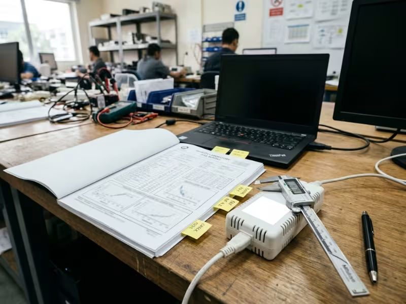
A datasheet tells you what a supplier wants to highlight. A test report tells you what the supply actually proved. Before I sign off on any supply, I send six questions, and the answers usually separate a strong candidate from a risky one within a day.
Ask them in writing. Vague replies often point to gaps in the evidence.
1. Do you have the full test report, or only a certificate?
A certificate shows that a supply passed. The full IEC 60601-1 report, ideally a CB report, shows how it passed, including measured leakage, spacing, temperature rise, and fault test results. Your lab needs that detail to accept the supply without retesting it. If a supplier sends only a one-page certificate and avoids the report, treat that as a red flag.
2. What MOPP or MOOP rating is documented?
“Medical grade” doesn’t tell you the rating. Ask for the exact rating, such as 2 MOPP or 2 MOOP, and the working voltage behind it. Check that the report states the rating for the primary-to-secondary barrier, and for primary-to-earth and secondary-to-earth if your design depends on them. A 2 MOPP claim on the marketing sheet and a 1 MOPP result in the report is a mismatch I see more often than you’d expect.
3. What are the leakage values at real input conditions?
Many datasheets quote “typical” leakage at 115 V. Your lab will measure at 110% of your highest rated voltage, often 264 V at 60 Hz. Ask for touch current and earth leakage at that voltage, in both normal and single fault conditions, and whether the supplier measured at full load or no load. Those figures set the share of your leakage budget the supply takes.
4. Do you have IEC 60601-1-2 EMC data?
CISPR 32 results from the ITE world won’t answer a medical reviewer’s questions. Ask for 60601-1-2 data, including CISPR 11 emissions class and the immunity levels tested, and confirm whether the supply met professional or home healthcare levels. Then ask one more thing: did it pass with an external filter? If so, that filter becomes part of your design and your leakage budget.
5. Under what mounting, thermal, and altitude conditions was the supply qualified?
A supply tested flat on a bench at 25 °C may struggle upright inside a sealed cart at 40 °C. Ask for the tested mounting orientation, the cooling method, the maximum ambient, and the derating curve. Ask for the altitude rating too, since many reports stop at 2,000 m and higher altitudes call for wider clearances. If your device runs outside those conditions, the lab may repeat the temperature and spacing checks.
6. What conditions of acceptability apply?
This page in the CB report gets skipped most often, and it matters most. It lists what your end product must still provide or prove, such as a required earth connection, an end-product enclosure, a specific fuse, or repeat temperature tests in the final assembly. Read it before you place the order. Each condition becomes a task on your submission plan.
Keep every answer in your decision record. When the lab asks about your supply, you’ll already have the proof in hand.
FAQs
What does ITE mean in power supplies?
ITE stands for Information Technology Equipment. An ITE power supply is built for products like laptops, routers, monitors, printers, and lab instruments.
Today, ITE supplies follow IEC 62368-1, which replaced IEC 60950-1. That standard protects ordinary users, trained staff, and service technicians. It assumes each of them can feel a shock and pull away.
For medical work, the key point is simple. An ITE rating tells you the supply is safe in an office or lab. It says nothing about protecting a patient who is sedated, wet, or wired to electrodes. So treat “ITE” as a description of the intended setting, not as a lower quality grade.
Can I use an ITE power supply in a medical device?
Yes, but only in specific setups. Three are common:
- No applied parts. Only staff touch the device, and nothing connects to the patient.
- A separate MOPP barrier. An isolated patient front end provides the full patient protection, so the ITE supply sits on the operator side.
- Outside the patient environment. The supply sits more than about 1.5 m from the patient as part of an ME system, often with a separating transformer.
Even then, your device enclosure usually must stay under 100 µA touch current in normal condition. Many ITE adapters exceed that alone. Measure leakage at 110% of rated voltage before you commit.
What is the difference between MOPP and MOOP?
The difference is who the barrier protects. MOOP (Means of Operator Protection) protects the person using the device. MOPP (Means of Patient Protection) protects the patient, who may not react to a shock.
MOPP asks for more margin. At a 250 V working voltage, typical figures look like this:
- 2 MOOP: about 5 mm creepage, 4 mm clearance, 3,000 Vac test
- 2 MOPP: about 8 mm creepage, 5 mm clearance, 4,000 Vac test
Those numbers change the transformer, the optocouplers, and the PCB layout. As a practical default, if a path from mains can ever reach the patient, plan for 2 MOPP from the first schematic.
What is the difference between Type B, BF, and CF?
These labels describe how an applied part connects to the patient. Each step up tightens leakage limits.
- Type B: The part touches the patient and may connect to earth. Patient leakage stays under 100 µA in normal condition. Some exam lights and patient tables fall here.
- Type BF: The patient connection floats from earth behind an isolation barrier. The limit stays at 100 µA normal and 500 µA single fault. SpO2 clips, BP cuffs, and temperature probes usually fit here.
- Type CF: The part can reach the heart. Patient leakage drops to 10 µA normal and 50 µA single fault. ECG leads and invasive pressure lines fall here.
Your risk file, not the catalog, should confirm each rating.
Which standard applies: IEC 60601-1 or IEC 62368-1?
The intended use of the finished device decides. If your product has a medical purpose and runs from mains, it falls under IEC 60601-1. That holds even if it has no applied parts.
IEC 62368-1 still matters inside that device. A lab can accept an ITE-rated component when your design gives it the right context, for example when the supply sits behind a MOPP barrier or outside the patient path.
So the device follows 60601-1, and each component must prove it fits that framework. A 62368-1 report helps on the operator side. It won’t answer patient leakage, essential performance, or applied part questions, so your 60601-1 report has to cover those.
Does a medical power supply still need certification if the full device will be tested?
Strictly speaking, no. The lab can evaluate an uncertified supply as part of your device. In practice, that choice usually costs you.
Without its own 60601-1 report, the lab must check the supply’s spacing, transformer construction, temperature rise, and fault behavior in your product. That adds weeks and lab fees, and it puts a part you didn’t design on your critical path. A supplier change later can trigger re-evaluation too.
A supply with a full CB report lets the lab accept that evidence. Request the full report, not just the certificate. Then read the conditions of acceptability, because they list exactly what your device still has to prove.
Conclusion
Price, wattage, and form factor can make two supplies look interchangeable. They aren’t. One question separates them: can current from your device ever reach the patient?
If nothing touches the patient, an ITE supply can work with the right system design. Once an applied part enters the design, IEC 60601-1 sets the rules, and the supply has to prove it belongs on that path.
Before you request your first quote, take three steps:
- Classify every applied part. Mark each patient connection as B, BF, or CF, and record the reasoning in your risk file.
- Set the system leakage budget. Subtract the supply’s leakage at 110% of rated voltage. Then confirm the remainder still covers your display, EMI filter, and isolated front end.
- Shortlist from real reports. Ask for the full test report or CB report. Check the MOPP rating and the conditions of acceptability. Drop any supplier that only sends a certificate.
Once you finish those three steps, you can usually narrow the field to one or two supplies.