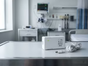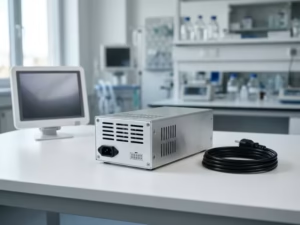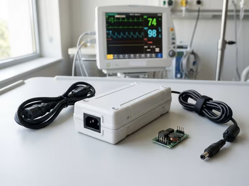
Many teams treat AC-DC and DC-DC converters as two versions of the same power module. In a medical device, you cannot swap one for the other. Each one does a different safety job.
Pick the wrong one, and the damage goes beyond efficiency or board space. Isolation falls short. Leakage climbs past the limit. EMC tests fail, and certification slips by weeks or months.
I work with design teams on these choices all the time. Most problems I see don’t come from a bad part. They come from a power tree where nobody decided which stage protects the patient.
In this guide, I explain how AC-DC and DC-DC stages work together in real medical power supplies. You’ll learn when to use AC-DC, when to use DC-DC, and when your device needs both.
Start With the Architecture Question
When a team asks me, “Do we need AC-DC or DC-DC?”, I don’t answer right away. First, I ask them to sketch the power path from the wall or battery to every circuit that touches a person.
Two questions shape that sketch. Answer them well, and the converter choice gets much easier.
Where Does the Power Actually Come From?
Start with the source, not the module. Most devices fall into one of three groups.
- Mains only. Bedside monitors, lab analyzers, and imaging carts plug into the wall. You need an AC-DC stage, either inside the device or as an external adapter.
- Battery only. Some handheld tools and wearables never connect to mains during use. DC-DC converters do most of the work here.
- Both. Infusion pumps, portable monitors, and docked devices run on battery but charge from the wall. This group needs the most care. The charger brings mains back into the design, even if the device spends most of its life unplugged.
List every way power can enter the device, including docks, chargers, and USB ports. Treat each entry point as a possible mains path.
Where Does the Patient Isolation Barrier Belong?
Next, map who touches what. Three situations cover most designs.
- No patient contact. A lab centrifuge or pharmacy cabinet mainly protects the operator. One well-chosen AC-DC supply often covers the isolation you need.
- Body contact. BP cuffs, SpO2 clips, and surface electrodes touch the skin. You now need patient-level protection between mains and that contact point.
- Patient-connected subsystem. ECG front ends and other floating measurement circuits need their own isolated domain. A dedicated isolated DC-DC stage often creates that domain right next to the sensor.
Map every port, probe, and cable that can reach the patient. The strictest one sets your bar.
Why This Decision Shapes Everything Else
Here is the idea I come back to in every design review. In a medical device, the first decision is not which power module to pick, but which stage in the power architecture carries each safety and isolation responsibility.
That assignment ripples through the whole design. It sets your creepage distances and leakage budget. It decides where EMC filtering lives and where heat builds up. It also shapes what your test lab looks at first.
Skip this step, and you may build two barriers where you needed one, or one where you needed two. Test labs catch both mistakes, and they usually catch them late.
What AC-DC and DC-DC Actually Do
The names sound similar, and that causes confusion even among experienced engineers. Both convert power, and both can include a transformer. But they sit in different places and carry different jobs.
Let’s look at each one by the role it plays, not the label on the datasheet.
AC-DC Supplies: The Gate Between Mains and Your Device
An AC-DC supply takes power from the wall and turns it into stable DC. That sounds like one job. Inside the supply, it breaks into several steps:
- EMI filtering keeps switching noise off the mains line and blocks line noise from getting in.
- Rectification turns the AC waveform into a high-voltage DC bus, often around 380–400 VDC after PFC.
- Power factor correction (PFC) shapes the input current. Above about 75 W, harmonic limits usually make active PFC necessary.
- Primary isolation separates the mains side from the low-voltage outputs. In a medical supply, this barrier often provides 2xMOPP.
You’ll usually see AC-DC supplies in three forms. Open frame boards mount inside a solid chassis. Enclosed units add a metal cover and often a fan. External adapters keep mains voltage outside the device, which suits home and portable products.
Whatever the form, this stage faces surges, sags, inrush, and line noise first. It is the first line of defense for everyone near the device.
DC-DC Converters: Shaping Power You Already Have
A DC-DC converter starts with DC that already exists. That might be a 24 V bus from an AC-DC supply, or a lithium cell sitting at 3.7 V. The converter steps that voltage up or down to suit a specific circuit.
DC-DC converters come in two main types, and the difference matters a lot in medical work:
- Non-isolated converters, such as buck and boost regulators, share a common ground. They’re small, efficient, and cheap. Use them for logic rails, processor cores, and displays.
- Isolated converters use a small transformer to build a separate ground domain. Medical-grade modules can provide patient-level isolation with very low barrier capacitance, which keeps leakage down.
In medical designs, I see DC-DC converters in three common places. They power local subsystems, such as a motor driver or a 1.8 V processor core. They create floating patient front ends for ECG, SpO2, or invasive pressure. And they build every rail in battery-powered devices, where one cell has to feed many circuits.
Same Building Blocks, Different System Jobs
Here’s where many engineers get tripped up. Open almost any AC-DC supply, and you’ll find a DC-DC stage inside. After rectification, a flyback or LLC converter steps the high-voltage bus down across the isolation transformer.
So technically, the two overlap. At the system level, their roles don’t.
The AC-DC supply decides how power enters your device. DC-DC converters decide how that power moves, splits, and gets isolated once it’s inside.
When I review a power tree, I don’t ask what topology a block uses. I ask which boundary it guards. Answer that for every converter, and your leakage, EMC, and certification plans get much easier to build.
The Real Difference in Medical Design
On a datasheet, AC-DC and DC-DC look like two ways to make a clean voltage. In a medical device, they split up the safety work. Your test lab will check whether each stage actually handles the risks you assigned to it.
Here’s how I break down those duties when I review a new power architecture.
AC-DC Carries the Mains Safety Burden
The AC-DC stage meets the grid first, so it absorbs most of the grid’s risk. I check five things.
- Mains isolation. This is your main barrier against shock. A 2xMOPP supply must pass a 4,000 VAC isolation test with about 8 mm of creepage at 250 VAC working voltage.
- Inrush current. Bulk capacitors charge almost instantly at power-on. Several devices on one crowded cart can trip a breaker if nobody plans for it.
- PFC. Above roughly 75 W, active PFC is usually required. It adds parts, heat, and its own noise.
- Hold-up time. During a brief mains dip, the bulk capacitor keeps the outputs steady, often for 10–20 ms. That window lets your battery or alarm circuit take over.
- AC-side EMI. The input filter keeps conducted noise off the building wiring. Its Y-capacitors also pass leakage current, so every filtering choice shrinks your leakage budget.
If the AC-DC stage gets any of these wrong, nothing downstream can fully fix it.
DC-DC Creates Local Rails or a Second Barrier
Once power is inside the device, DC-DC converters take over. Their jobs are more local, but they can be just as safety-critical.
Subsystem isolation. A motor driver or display backlight can run from its own converter. That keeps its noise and faults away from the rest of the board.
Patient-connected front ends. An ECG or SpO2 circuit often needs a floating domain. An isolated DC-DC module creates that domain next to the sensor. It can also provide a second MOPP, or the only MOPP that faces the patient.
Distributed architecture. Many larger systems run a 24 V or 48 V bus from one AC-DC supply, with point-of-load converters at each circuit. That gives you flexibility, but every converter adds another noise source and another heat source.
Battery Power Doesn’t Make Safety Go Away
I hear this assumption all the time: “It runs on a battery, so we can skip the medical isolation work.” That idea has delayed more submissions than almost any other mistake I see.
Here’s what stays with you after you remove the power cord.
The patient is still there. A battery-powered ECG patch still connects to the body. It is still a BF or CF applied part, and patient leakage limits still apply.
Insulation analysis still applies. You still need proper separation between the applied part and accessible conductive parts. If the device must survive a defibrillator pulse, the front end needs defibrillation-proof protection whatever the power source.
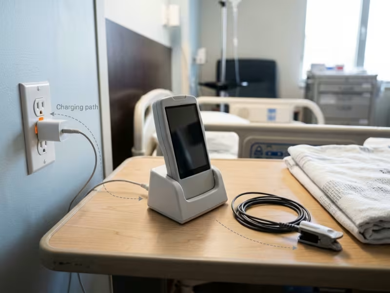
The charging path brings mains back. This is the part teams miss most often. Here’s a concrete case. A cheap consumer charger with a 2.2 nF Y-capacitor at 230 VAC and 50 Hz passes about 160 µA. If a patient wears the device while it charges, that current can find a path through the electrodes. That’s already above the 100 µA normal-condition patient leakage limit for BF.
Before you call a device “battery-only,” I ask teams three questions:
- Can the patient use the device while it charges? If yes, test it as mains-connected equipment in that state.
- Can anyone touch the charging contacts and the patient at once? If yes, the contacts join your leakage analysis.
- Does a USB cable link the device to a PC? A grounded PC opens a leakage path around your charger’s isolation.
If you answer “no” to all three, and your design and labeling enforce it, your safety case gets much simpler. If you answer “yes” to any of them, plan for 2xMOPP in the charging path.
Isolation Responsibility Is the Real Question
Put these pieces together, and one idea stands out. The key question is not how a stage converts power. It is which stage owns each isolation duty.
Two designs can use similar parts and still have very different safety cases. Design A uses a 2xMOPP AC-DC supply and an isolated DC-DC module to float the ECG front end. Design B splits protection, with 1xMOPP in the AC-DC stage and 1xMOPP in the DC-DC module. Both can pass. But Design B makes the DC-DC module a safety-critical part, with more documentation and tighter change control.
So I ask teams to label every block in the power tree as a mains barrier, a patient barrier, or no barrier. Mark each barrier’s MOPP or MOOP count, working voltage, and test voltage. That one page shows your test lab exactly where the protection lives.
Isolation, Leakage, and Applied Parts
This is where the AC-DC vs. DC-DC question stops being abstract. Your isolation plan decides how much leakage reaches the patient and which stage your lab will examine most closely.
I start by sorting out who needs protection and how much. Then I look at where each barrier sits.
MOOP and MOPP in Plain Terms
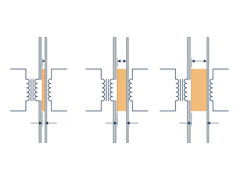
MOOP (Means of Operator Protection) protects the nurse or technician. They touch the enclosure and controls, and they can let go if something feels wrong.
MOPP (Means of Patient Protection) protects the patient, who may be sedated, wired to electrodes, or too weak to pull away. So MOPP asks for more spacing and higher test voltages.
At 250 VAC working voltage, typical reference figures look like this:
- 1xMOOP: 1,500 VAC test, about 2.5 mm creepage
- 1xMOPP: 1,500 VAC test, about 4 mm creepage
- 2xMOPP: 4,000 VAC test, about 8 mm creepage
You need two means of protection between mains and the patient. The standard doesn’t require both to sit in the same part. That flexibility is exactly why the AC-DC vs. DC-DC decision matters.
When the AC-DC Stage Is Enough, and When It Isn’t
I don’t answer this with a rule. I answer it with the device in front of me. Four cases cover most designs.
Wall-powered, no patient-connected applied part. Think of a lab analyzer or specimen fridge. A 2xMOOP or 2xMOPP AC-DC supply often handles everything, with non-isolated converters downstream. Just confirm that an operator can’t touch the device and a patient at the same time.
Wall-powered, with BF or CF circuitry. A 2xMOPP supply may cover a single BF channel if your leakage budget holds. CF is different. Normal-condition patient leakage must stay under 10 µA, and the mains-on-applied-part test allows only 50 µA. A typical AC-DC transformer has too much barrier capacitance to get there alone.
Battery device with a charging dock or adapter. If patients never use the device while it charges, a 2xMOPP medical adapter can be enough. If they can, or if you can’t control which charger they grab, add isolation inside the device.
Isolated front end inside a larger system. A multi-parameter monitor may run ECG, invasive pressure, and temperature from one supply. Each channel needs its own floating domain, so current can’t flow between sensors through the patient’s body. Only isolated DC-DC modules can create those separate domains.
Design Situation | AC-DC Only May Be Enough? | Isolated DC-DC Likely Needed? | Why |
|---|---|---|---|
Wall-powered, no applied part | Yes | No | Operator protection and touch current are the main concerns |
Wall-powered, Type B applied part | Usually | Rarely | A 2xMOPP supply often covers it; check enclosure touch current |
Wall-powered, single BF channel | Often | Sometimes | Y-caps, cables, and ports can use up the leakage margin |
Wall-powered, CF applied part | No | Yes | 10 µA needs a low-capacitance barrier near the patient |
Battery device, no use while charging | Yes, at the adapter | Sometimes | Design and labeling must truly prevent use during charging |
Battery device, used while charging | No | Yes | Mains reaches the patient through the charging path |
Multi-channel patient front ends | No | Yes | Each channel needs its own floating domain |
Device with USB or Ethernet to a PC | Sometimes | Often | Data ports open new leakage paths to grounded equipment |
Use the table to narrow choices early. Then confirm with your leakage budget and the particular standard for your device.
Why Isolated DC-DC Modules Sit Near the Patient
The table shows a clear pattern. Patient-connected circuits keep pulling isolated DC-DC modules into the design. I place them as close to the sensor as the layout allows, for four reasons.
They create a local floating domain. The patient circuit gets its own ground, separate from earth and the rest of the board. That’s the “F” in BF and CF.
They control leakage. Leakage through a barrier tracks its capacitance. A medical-grade module with about 10 pF passes roughly 1 µA at 264 VAC and 60 Hz. A general-purpose module at 1,000 pF passes close to 100 µA. That gap decides whether a CF design passes.
They protect signal quality. ECG signals sit near 1 mV. Low barrier capacitance blocks common-mode noise from the main supply, motors, and displays. Pick a module with a fixed switching frequency outside your signal band, and add an LDO on the patient side.
They contain faults. If a sensor shorts or a defibrillator pulse hits the leads, the barrier keeps the damage local. The rest of the device keeps running and can raise an alarm.
Pair every isolated power stage with a digital isolator for the data lines. A strong power barrier won’t help if a non-isolated SPI line crosses the gap.
A Certified Module Doesn’t Replace System Leakage Testing
This point saves teams more grief than any other. A module with an IEC 60601-1 report proves the module meets its own ratings. It doesn’t prove your device passes.
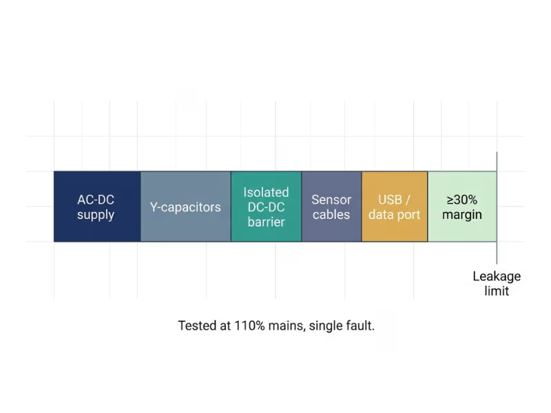
Your lab measures leakage on the finished product. Y-capacitors add current. So does stray capacitance in every transformer and isolated converter. Sensor cables, shielded leads, and a USB port tied to a grounded PC each add more. The lab tests at 110% of rated mains and under single-fault conditions, such as an open protective earth.
Every certified part can sit under its own limit while the total still fails. I’ve seen a device pass every component check and miss its CF limit by a few microamps.
So I ask teams to build a leakage budget per path, keep at least 30% margin, and read each module’s conditions of acceptability. Then measure on the first powered prototype, not two weeks before submission.
How the Choice Affects EMC, Thermal, and Reliability
Your isolation plan decides where each converter sits. That placement then shapes noise, heat, and long-term reliability.
None of these follow a simple “AC-DC good, DC-DC bad” rule. Each one depends on where conversion happens and how many stages you stack.
EMC Looks Different on Each Side of the Supply
I treat AC-side and DC-side noise as two separate problems.
On the AC side, the concern is what leaves the device. Conducted emissions from 150 kHz to 30 MHz travel back onto the mains line, and the input filter is your main defense. The catch is that Y-capacitors that cut common-mode noise also add leakage. Settle that trade-off with your safety team early.
On the DC side, the concern is what reaches your own circuits. A converter switching at 500 kHz can couple ripple into an ADC reference or ECG amplifier. You won’t see it as a failed emissions scan. You’ll see it as a noisy baseline or a drifting reading.
Distributed converters multiply noise sources. Two converters at 400 kHz and 420 kHz can create a 20 kHz beat that lands in a sensing or audio band. Light-load burst modes can also drop noise right into the ECG band below about 150 Hz.
A few habits keep multi-rail designs under control:
- Sync converters to one clock where the modules allow it.
- Add a small LC filter or ferrite bead at each sensitive point of load.
- Keep high-current switching loops tight and away from patient-side traces.
- Run a near-field probe scan on the first prototype to find the loud converter early.
Heat Follows the Conversion Stages
Every conversion stage turns some power into heat. Where you put those stages decides where your hotspots form.
A centralized AC-DC design keeps heat in one place. You can cool it with one heat sink, one airflow path, or one chassis contact. That’s simpler to design and verify.
A distributed design spreads heat across the board. That sounds better, but it can backfire. A 1–2 W isolated module often runs at only 75–85% efficiency. Tucked beside a sensor front end, it can warm a voltage reference enough to shift readings.
Efficiency losses also stack. A 100 W load through a 90% AC-DC supply loses about 11 W. Add a 92% DC-DC stage, and overall efficiency drops to about 83%. Now you lose nearly 21 W. In a sealed, fanless enclosure, that extra 10 W can push internal air well past your derating point.
For sealed systems, mount high-loss stages against the metal chassis. Keep converters away from skin-contact surfaces. Log temperatures at every module, not just the main supply.
More Stages: Better Architecture or More Failure Points?
The honest answer is that it can go either way.
Extra stages can make a design stronger. An isolated module can contain a fault in one subsystem and keep alarm logic alive. It also lets you reuse a proven AC-DC supply across several products and change only the downstream rails.
Extra stages also add risk. Failure rates add up in series. Two modules rated at 500,000 hours MTBF each give you roughly 250,000 hours combined. Each stage also adds single-fault cases to your risk file. If a DC-DC stage carries a MOPP, it becomes a safety-critical part with tighter change control.
My test is simple. Every conversion stage should have one clear job that nothing else in the design can do. If you can’t name that job in one sentence, the stage probably adds heat, noise, and risk without adding value.
Where Each Approach Fits Best
Theory only gets you so far. Most teams don’t design a “converter.” They design a monitor, a pump, or a patch.
So I sort projects into three device scenarios. Each one points toward a different architecture.
Wall-Powered Stationary Equipment
Patient monitors, ventilators, lab analyzers, and imaging subsystems plug into hospital mains and stay there. An internal AC-DC supply is the natural starting point.
The common setup is simple. An open-frame or enclosed supply builds a 12 V, 24 V, or 48 V bus. Non-isolated buck converters then create the 5 V, 3.3 V, and core rails. The AC-DC stage carries the mains barrier, and the downstream converters only handle voltage.
The picture changes once a patient connection enters the design:
- Lab analyzers often need nothing more than a 2xMOOP or 2xMOPP supply and non-isolated rails.
- Ventilators need an AC-DC supply sized for blower peaks, plus a battery that feeds its own DC-DC stage. Check any SpO2 or ECG accessory ports, since those bring BF or CF requirements back.
- Patient monitors almost always need isolated DC-DC stages for their sensor channels.
- Imaging subsystems often pair a configurable AC-DC supply with isolated DC-DC converters on noise-sensitive rails.
My advice: don’t ask the main supply to solve a CF leakage problem. Let it guard the mains, and add a local barrier where the patient connects.
Battery-Powered Portable and Wearable Devices
Handheld diagnostics, ambulatory infusion pumps, and wearables flip the balance. DC-DC converters become the core of the power tree.
A single Li-ion cell swings from about 4.2 V down to 3.0 V. Buck-boost converters hold steady rails across that range for the processor, radio, display, and motor driver. I look closely at light-load efficiency and quiescent current, because many of these devices spend most of their life asleep.
But the AC-DC stage never fully leaves. It moves into the charger, the dock, or the USB-C adapter a patient grabs at home. Each of those paths needs a place on your isolation diagram.
So decide early whether patients can use the device while it charges. If they can’t, a 2xMOPP adapter and clear labeling may cover you. If they can, plan a low-capacitance isolated DC-DC stage between the charging circuit and the patient side.
Hybrid Systems With Patient-Connected Subsystems
This is the scenario I spend the most time on. It’s also where the “AC-DC or DC-DC” question falls apart, because the honest answer is both, in layers.
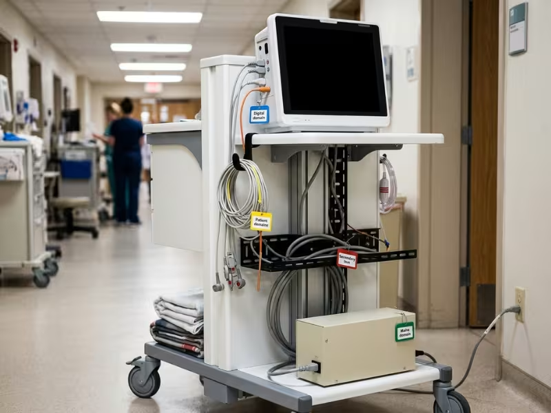
Picture a multi-parameter monitoring cart. A central 2xMOPP AC-DC supply builds a 24 V bus. Non-isolated converters power the processor, display, and network module. Each patient channel, such as ECG or invasive pressure, gets its own isolated DC-DC converter right next to the sensor.
I think of these systems as a stack of domains: the mains domain, the secondary bus, the digital domain, and one or more floating patient domains. A fault on the ECG leads stays in the ECG domain.
Two details catch teams most often. First, power isolation is only half of each boundary. Pair each isolated module with a digital isolator rated to the same protection level. Second, check every patient domain against defibrillation and single-fault cases. The module must survive a defib pulse without passing energy back to the shared bus.
Device Scenario | Typical Architecture | Main Reason |
|---|---|---|
Lab analyzer, no applied part | Internal AC-DC + non-isolated DC-DC rails | AC-DC carries the only barrier needed |
Patient monitor or ventilator | Internal AC-DC + battery backup + isolated DC-DC for sensors | Mains protection plus floating patient domains |
Imaging subsystem | Enclosed or configurable AC-DC + isolated DC-DC per sensitive rail | Many rails and strong noise separation |
Handheld diagnostic | Battery + DC-DC rails + external 2xMOPP adapter | Battery is the main source; adapter carries mains barrier |
Wearable or ambulatory pump | Battery + high-efficiency DC-DC + isolated stage if used while charging | Low heat, long run time, safe charging path |
Cart or rack with patient modules | Central AC-DC bus + isolated DC-DC and data isolation per module | Layered domains contain faults and control leakage |
How to Choose Between AC-DC, DC-DC, or Both
When a team brings me a half-finished power tree, I walk them through the same six steps. The order matters more than the parts.
By the time you open a vendor catalog, you should already know what you need.
1. Identify the Incoming Power Source
Write down every way energy can enter the device, not just how it usually runs. Mains only means an AC-DC stage. Battery only means DC-DC carries the load. Both means you need both stages and a clean handoff between them.
Count chargers, docks, and service ports as sources. A USB service port can link a “battery-only” device to a grounded laptop.
2. Identify Whether Any Circuit Touches the Patient
List electrodes, probes, cuffs, sensor cables, and any housing surface in long skin contact. Mark each as Type B, BF, or CF, then flag the strictest one. That single applied part often decides your whole architecture.
3. Decide Where the Isolation Barrier Must Sit
Draw a block diagram and place each barrier on it. For each one, record the stage that provides it, its MOPP or MOOP rating, its working voltage, and its test voltage.
If you split protection between stages, show that clearly. Then check every signal line that crosses a barrier.
4. Check Leakage, EMC, and Thermal at System Level
Run three quick checks before anyone orders samples. Add up leakage from Y-caps, barriers, and ports, and keep at least 30% margin. Note every switching frequency and its beat products. Multiply stage efficiencies and estimate heat inside your real enclosure.
If a check fails, go back to step 3. Fixing it on paper costs far less than fixing it on a board.
5. Decide Whether Centralized or Distributed Is Safer
Centralized designs suit devices with no patient-connected circuits, tight space, or strict noise budgets. Distributed designs suit devices with several patient channels or alarm circuits that must survive a subsystem fault. Either way, every stage needs one job you can name.
6. Only Then Compare Modules, Form Factors, and Vendors
Now you have a specification, and the catalog becomes useful. Screen each candidate for:
- Isolation rating and barrier capacitance that match your assigned barrier
- Conditions of acceptability that fit your mounting, spacing, and airflow
- Derating curves at your real internal temperature
- Form factor: open frame, enclosed, external adapter, or board-mount module
- Documentation, including the CB report, EMC data, and ISO 13485 status
- Lifecycle support, including a written PCN policy and last-time-buy terms
It also pays to confirm the supplier can support documentation, validation, and controlled production through qualified facilities. Send the same list to two or three vendors and compare answers side by side.
Common Mistakes That Delay Validation
Validation delays rarely come from one big error. They come from small assumptions nobody checked. These six show up in almost every review I run.
1. Treating AC-DC and DC-DC as interchangeable
What teams assume: Any module that fits the board and budget will do.
What actually happens: A cheap non-isolated buck converter “cleans up” the patient rail but adds no barrier. The lab finds the BF circuit shares ground with the secondary bus, and the layout goes back to the drawing board.
2. Assuming battery power removes isolation analysis
What teams assume: No power cord means no mains risk.
What actually happens: A dock, adapter, or USB port reconnects the device to mains. A consumer charger’s Y-capacitance pushes patient leakage past the BF limit.
3. Using a certified supply as proof of device compliance
What teams assume: Certified AC-DC and DC-DC parts mean the device is mostly covered.
What actually happens: Each report covers one part under its own conditions. If your enclosure runs hotter or your PCB spacing falls short, the certificate stops helping.
4. Mixing isolated and non-isolated grounds carelessly
What teams assume: The isolated module floats the patient circuit, so the job is done.
What actually happens: A data line, cable shield, test point, or copper pour bridges the barrier. Hipot fails, or patient leakage jumps.
5. Ignoring leakage and EMC until late testing
What teams assume: Formal testing will simply confirm good parts.
What actually happens: Y-caps that pass emissions push leakage over the limit. Remove them, and EMC fails. Two weeks before submission, there’s no room to balance the two.
6. Forgetting thermal derating in the final enclosure
What teams assume: The datasheet shows plenty of headroom.
What actually happens: Air near the supply runs 15–20°C above room temperature, and each DC-DC stage adds more. The supply trips at peak load, or a warm module shifts sensor readings.
All six share one root cause: the team chose parts before deciding which stage carries which job.
Validation Checks Before Freezing the Design
Once the layout locks, every fix gets slower and more expensive. Run these six checks on the first full prototype, with the real enclosure, cables, and accessories in place.
- Dielectric strength (hipot). Test each barrier at its assigned rating, such as 4,000 VAC for one minute across 2xMOPP. Ramp slowly, and decide upfront how you’ll handle Y-caps across the barrier.
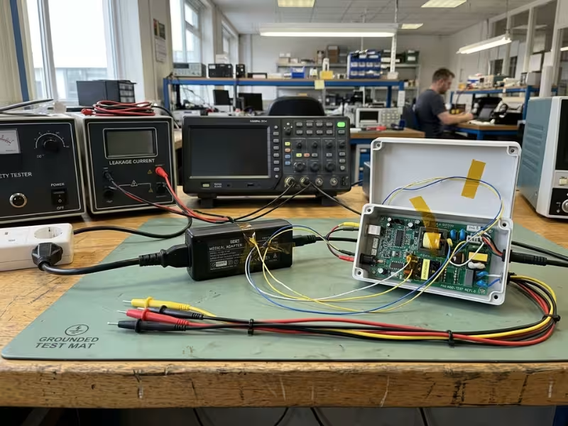
- Leakage current. Test at 110% of rated mains in normal and single-fault conditions. For F-type parts, apply mains to the patient connection. Measure while charging if patients can use the device that way.
- EMC pre-scan. Check conducted emissions from 150 kHz to 30 MHz with a LISN. Use a near-field probe to find the loudest converter, and aim for at least 6 dB of margin.
- Thermal soak. Run at maximum load and ambient until temperatures settle. Check every converter against its derating curve, and keep long-contact applied parts at or below 43°C.
- Worst-case load transients. Cold-start at low line and low temperature. Trigger your biggest peak and pull mains for 10–20 ms. No rail should dip below brownout, and no alarm should drop out.
- Grounding and isolation review. Compare the physical board to your isolation diagram. Measure creepage on the real PCB and trace every conductor that crosses a barrier.
If all six pass with margin, freeze the design with confidence.
FAQs
What is the main difference between AC-DC and DC-DC in a medical device?
An AC-DC supply brings mains into the device and carries primary isolation, inrush, PFC, hold-up, and line-side EMI. A DC-DC converter works from existing DC, builds local rails, and often creates floating patient domains.
Do battery-powered medical devices still need isolated DC-DC converters?
Often, yes. Applied-part leakage limits still apply, and the charging path can bring mains back. If patients can use the device while it charges, plan an isolated stage between the charger and the patient side.
Does a medically certified AC-DC supply make the whole device compliant?
No. The certificate covers the supply under its own conditions of acceptability. Your lab still tests the finished device with every cable, port, and accessory attached.
When is an isolated DC-DC stage needed after an AC-DC front end?
Add one for CF applied parts, ECG or pressure front ends on a shared bus, multiple patient channels, or devices used while charging. Pair it with isolated data lines rated to the same level.
Can an industrial DC-DC converter be used in a medical product?
Only where it carries no safety duty, such as a local rail far from any patient connection. For any MOPP role or floating applied part, choose a medical-grade module with an IEC 60601-1 report and low barrier capacitance.
Is a distributed DC-DC architecture always better?
No. It can contain faults and separate noise, but it adds parts, heat, and switching sources. Each stage should earn its place with one clear job.
How do IEC 60601-1 and IEC 60601-1-2 affect this choice?
IEC 60601-1 sets isolation, creepage, test voltage, and leakage rules, which decide where barriers sit. IEC 60601-1-2 sets EMC limits, which decide your filtering. Y-caps link the two, so balance them early.
Draw the Boundaries First, Then Pick the Parts
AC-DC and DC-DC are not rival options. They are layers. The AC-DC stage meets the mains and takes on the line-side risk. DC-DC converters shape the DC you already have into local rails, and they often float the circuits that touch the patient.
The module labels won’t decide whether your device passes. Responsibility will. Which stage carries each barrier? Which one adds the most leakage? Where does switching noise start, and where does heat build up?
So start with a sheet of paper, not a catalog. Sketch the power tree from the wall socket or battery to every rail. Mark each isolation boundary with its rating, its working voltage, and the stage that provides it. Trace every data line that crosses a barrier.
Once that drawing holds up, shortlist modules that fit it from your current vendors or a broader range of power products. Teams that work in this order catch problems on paper. Teams that reverse it usually find them in the test lab.