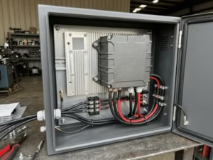
Sealed equipment traps heat fast.
A fan can move that heat out. But it can also pull in dust, moisture, salt, and oil mist. In many outdoor and industrial systems, that tradeoff causes more trouble than it solves.
That is why conduction cooled power supplies matter. They remove heat without relying on airflow. But they only work well when the thermal path is designed well.
I often see teams choose the right product and still get the wrong result. The power supply is fine. The mounting surface is not. The enclosure is sealed, but the heat has nowhere to go.
This guide helps you avoid that mistake. It shows when to use a conduction cooled power supply, what to check first, and how to match the unit to the real enclosure, load, and environment.
Why Conduction Cooling Matters in Sealed Equipment
Sealed boxes exist for a reason. They keep dust, water, and grime away from sensitive electronics. But that same seal traps heat inside, and heat is what kills power supplies.
A fan seems like the obvious fix. It isn’t, not here. The moment you cut a vent for airflow, you break the seal you worked to build. Now the box breathes in everything you meant to keep out.
Harsh environments raise the stakes. Outdoor cabinets bake in the sun. Washdown areas get blasted with water and chemicals. Dusty plants clog filters in weeks. Vibration on rail and vehicles shakes fans apart. In each case, the cooling method decides whether the system survives or fails early.
Conduction cooling fits these settings because it needs no airflow at all. It hands heat to metal and lets the enclosure carry it away. Dust stays out. Water stays out. There are no fans to wear out and no filters to clean.
One warning, though. Fanless does not mean thermally safe. A conduction cooled supply only works when heat has a real route out of the box. Bolt it to the wrong surface, and it overheats just like anything else.
What a Conduction Cooled Power Supply Is
A conduction cooled power supply moves heat through metal, not air. Instead of blowing hot air off its parts, it carries that heat into a solid surface and lets the surface take it away.
Here is how the heat travels. It starts at the hot components inside, then follows a clear chain:
- Component → PCB
- PCB → thermal interface material
- Thermal interface material → baseplate
- Baseplate → mounting surface
- Mounting surface → ambient
Every link in that chain has to conduct well. If one link resists heat, the whole path slows down and the supply runs hot.
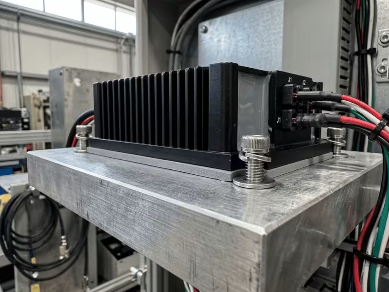
This is why the mounting surface is not just a place to bolt the unit. It’s the last stage of the cooling system. Bolt the supply to a cold plate, a thick enclosure wall, or a proper heatsink, and heat leaves fast. Bolt it to thin metal or leave an air gap, and heat backs up inside.
The difference from other methods is simple. A fan cooled supply pushes heat into moving air. A convection cooled supply lets warm air rise off it on its own. A conduction cooled supply skips air entirely and hands its heat to metal.
That single choice is what lets it live in a sealed box where airflow was never an option.
Conduction Cooling vs. Convection and Fan Cooling
Each cooling method solves the heat problem in a different way. The right pick depends on your enclosure, your environment, and how much maintenance you can live with.
Fan cooling moves the most heat, plain and simple. If you need high power in a small space, a fan handles it. But it needs open air, and that open air brings in dust, moisture, and grime. Fans also wear out, so you’re signing up for filter cleaning and eventual bearing failure.
Convection cooling keeps things simple. No fan, no moving parts. Warm air just rises off the unit on its own. The catch is that this only works in a vented enclosure. Seal the box, and convection has nowhere to send the heat.
Conduction cooling seals the electronics away from the outside world. Heat runs through metal instead of air, so dust and water stay out. But it lives or dies by the thermal path. Give the heat a solid route out, and it works beautifully. Block that route, and the supply cooks.
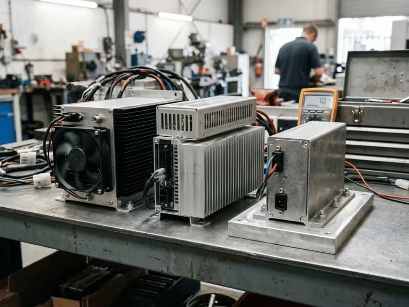
Here’s how the three stack up side by side:
Cooling Method | Needs Airflow? | Works in Sealed Enclosure? | Maintenance | Best Use Case | Main Limitation |
|---|---|---|---|---|---|
Fan Cooling | Yes | No | Regular (filters, fans) | High power in clean, accessible spaces | Pulls in contaminants; parts wear out |
Convection Cooling | Natural airflow | No | Low | Low-power gear in vented boxes | Needs vents; limited heat capacity |
Conduction Cooling | No | Yes | Minimal | Sealed, outdoor, or harsh settings | Only works with a good thermal path |
Read the table with your own setup in mind. A vented indoor cabinet gives you more options than a sealed box baking in the sun.
Start With the Thermal Path, Not the Nameplate Wattage
That big number on the data sheet tempts everyone. A 300W supply sounds like it can handle a 250W load with room to spare. But in a sealed box, that number can lie to you.
Nameplate wattage assumes ideal conditions. It’s the most the supply can deliver when its baseplate stays cool. The moment the baseplate heats up, available power drops. So the real question isn’t “how many watts?” It’s “how many watts at my baseplate temperature?”
Here’s the shift that saves projects: stop reading the free-air rating and start reading the baseplate rating. Free-air numbers describe a unit sitting in open space with heat rising off it. That’s not your enclosure. Your unit is bolted to metal, sealed away from the air. Baseplate temperature is the number that tells the truth about your setup.
Now think about where the heat goes after the baseplate. It flows into whatever you mount the supply against. That enclosure wall, cold plate, or heatsink is not an accessory bolted on for looks. It’s the final stage of the cooling system.
The mounting surface earns the same respect. People treat it as a bracket, a place to put screws. I treat it as a thermal component. A thick aluminum wall pulls heat away fast. A thin panel or a painted surface chokes the flow and traps heat inside the unit.
If heat can’t leave the box, the wattage on the label means nothing. A 300W supply with no exit path behaves like a much smaller one, then shuts down or fails early. So build the thermal path first. Then check what the supply can actually deliver inside it.
How to Read a Derating Curve Without Guessing
A derating curve tells you the truth the nameplate hides. It shows how much power the supply can really deliver as it heats up. Learn to read it, and you stop guessing.
Start at the flat part of the curve. That’s where the supply delivers full rated output. But look at the temperature under it. Full power usually holds only up to a set point, often around 50°C baseplate. Below that line, you get everything the label promises.
Past that point, the curve slopes down. Output drops in a straight line as the baseplate or ambient temperature climbs. The hotter it runs, the less it gives. This isn’t a defect. It’s the supply protecting itself.
Baseplate vs. ambient
Check which temperature the curve uses. Some plot against baseplate temperature, some against ambient air. They are not the same number.
Baseplate temperature is what your mounting surface actually reaches. In a sealed box, that runs well above room temperature. So a curve drawn against ambient can fool you if your baseplate sits much hotter. Always match the curve’s axis to the temperature you can actually measure in your enclosure.
A quick example
Say you find a 300W supply. On paper, that’s plenty for a 200W load.
Read the curve, though. It holds 300W up to 50°C baseplate. Above that, it derates. At 70°C baseplate, it delivers only 180W.
Now your 200W load doesn’t fit. The supply you thought had spare capacity can’t keep up in a hot cabinet.
This is why you never spec a supply at its peak nameplate rating for a warm enclosure. Measure your worst-case baseplate temperature first. Find that point on the curve. Read the real output there. Then pick a supply that clears your load with margin at that temperature, not at 25°C.
Mounting and Thermal Interface: Where Good Designs Often Fail
Most conduction cooling failures I see don’t start with the power supply. They start at the joint where the baseplate meets the surface. The unit is fine. The mounting is not.
Bolt two metal surfaces together and they look like they touch. They don’t. Under a microscope, both are rough. Real contact happens only at a few high points, and tiny air gaps fill the rest. Air is a terrible conductor, so those gaps block heat.
Thermal interface material fills them in. You have three common choices:
- Thermal pads are clean and simple. Good for flat, even surfaces where you want repeatable results.
- Thermal paste fills thin gaps well and conducts better than most pads. Messier, and it needs a flat mating surface.
- Gap fillers handle uneven surfaces or larger tolerances. Use them when the baseplate and wall don’t sit perfectly flush.
Match the material to the gap. A thick pad on a tight, flat joint wastes performance. Thin paste across an uneven surface leaves voids. For odd geometries or tight tolerances, a supplier that offers custom power adapters with tailored baseplates and interfaces can save you a lot of grief.
Flatness, contact, and torque
The material only helps if the surfaces let it. Flatness comes first. A warped enclosure wall leaves gaps the interface can’t fully bridge. Check the mating surface with a straightedge before you trust it.
Contact area matters just as much. Heat leaves through the metal that actually touches. Half the contact means roughly half the path. Torque ties it together. Too little, and the surfaces sit loose with air between them. Too much, and you warp the baseplate or crush a soft pad out of place. Follow the maker’s torque spec and use a torque wrench, not feel.
Watch for uneven pressure. When one corner is snug and another is barely turned, heat backs up at the loose corner and a hot spot forms right where you never looked. Tighten in a cross pattern, in steps, the way you’d torque a wheel.
Wall thickness and heatsink mass
The surface you mount to is the last leg of the path, so its size and mass matter. A thin panel heats up fast. A thick aluminum wall pulls heat away and holds it while it sheds to ambient. When the wall alone can’t cope, add a heatsink with enough mass and fin area for your worst-case load.
Bigger isn’t always the point. A well-placed heatsink bonded with good interface material beats a large one bolted on loose. Treat the mounting interface with the same care you give the electrical design. That’s where reliable conduction cooling is won or lost.
Environmental Conditions That Change the Right Choice
Two enclosures can hold the same load and still need different power supplies. The environment decides. Match the unit to where it actually lives, not to a spec that sounds impressive on paper.
IP rating: match it, don’t max it
More people over-buy IP rating than under-buy it. A higher number sounds safer, so they reach for IP68 when IP54 would do. That instinct costs you. A fully sealed, potted unit runs hotter, since potting slows heat flow. It also costs more and often ships on a longer lead time.
Read the rating for what it means. The first digit covers solids like dust. The second covers water, from light drips up to full submersion. A dusty control cabinet needs strong dust protection but little water protection. A washdown line needs the opposite. Pick the rating that fits your real threat.
Splash, washdown, and salt fog are different fights
People lump “wet” into one bucket. It isn’t one problem.
- Splash and drip are occasional and low pressure. Basic sealing handles them.
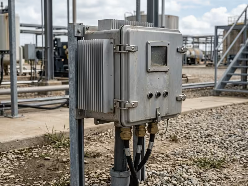
- Washdown means high-pressure jets, hot water, and cleaning chemicals hitting the unit on purpose. That demands tight seals and often stainless hardware.
- Outdoor exposure mixes rain, UV, and temperature swings over years. The seal has to survive time, not just water.
- Condensation forms inside the box, not outside. Warm, humid air gets trapped when you close the enclosure, then condenses when the unit cools.
- Salt fog attacks the metal itself, creeping into every joint and connector.
Conformal coating on the boards buys real protection against trapped moisture. So does a small breather vent with a membrane that blocks water but lets pressure equalize.
Temperature cycling and corrosive air
A steady 60°C is easier on a supply than a daily swing from 5°C to 55°C. Every cycle makes gaskets and interface materials expand, then contract. Over months, that flexing opens tiny gaps, and a seal that passed on day one starts to leak by year two. So don’t just check the temperature range. Check how often the unit crosses it.
Coastal sites, chemical plants, and wastewater facilities share one trait: the air itself eats hardware. Choose anodized aluminum for baseplates, stainless steel hardware where plain steel would rust, and sealed or coated connectors to keep salt out of the contacts. A supply that handles the watts fine will still fail if its baseplate corrodes and loses contact with the wall.
Electrical Specs That Still Matter in Harsh Environments
Thermal design gets you a supply that survives the heat. But a sealed box in the field faces more than heat. The power coming in is often dirty, and the load inside can be picky.
Wide input range and inrush
Field power is rarely clean. Rural grids sag. Generators drift. A narrow input window can’t ride that out. Pick a wide input range for anything on shaky power. A unit rated 85–305VAC, or a wide DC window like 9–36V, absorbs sags and surges without cutting out.
Inrush current deserves a look too. When the supply first powers on, it pulls a hard spike as its input capacitors charge. In a sealed cabinet feeding several units off one breaker, those spikes stack up and trip protection you didn’t expect. Size your upstream breaker for it.
Hold-up time and transient response
Hold-up time is how long the output stays alive after input power vanishes. A short blackout or a switchover to backup shouldn’t reboot your equipment. If your system needs to ride through a longer gap, look for a longer hold-up spec or plan for added capacitance. Just remember: more input capacitance raises inrush, so balance the two.
Transient response covers the other direction. When the load jumps suddenly, the output dips, then recovers. For loads that pulse hard, like radios that transmit in bursts, check how fast and how cleanly the supply settles. A sloppy recovery shows up as resets you’ll struggle to trace later.
Protection and isolation
Sealed equipment sits far from help, so the supply has to protect itself. Confirm these are built in:
- Overvoltage protection (OVP) shields the load if the output climbs too high.
- Overcurrent protection (OCP) limits current during a fault.
- Short-circuit protection shuts down cleanly and recovers once the fault clears.
- Thermal shutdown cuts output before the unit overheats, then restarts when it cools.
Check how thermal shutdown recovers. A supply that latches off needs a manual reset, which is a real problem in a cabinet on a pole. Auto-recovery keeps the system running once temperatures drop. Outdoor installs need surge protection on top of this.
Isolation matters more in two conditions. Altitude thins the air, so it insulates less; confirm isolation ratings at your real altitude. Pollution does the same from the other direction, so dusty or salty sites need larger creepage and clearance distances. Watch ripple and noise too. Rugged industrial loads tolerate a little. Sensors, precision instruments, and RF gear don’t, so check the spec against what your load can actually accept.
Mechanical Fit, Vibration, and Connector Choices
A supply that clears the thermal math can still fail on the mechanical side. How it fits, how it holds up to shaking, and how it connects all shape whether it survives.
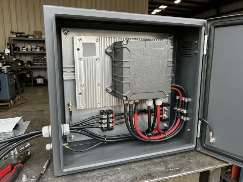
A chassis-mount or baseplate unit suits a sealed enclosure best. It bolts flat to a wall or cold plate, so the metal that seals the box also carries the heat. Open-frame supplies are the wrong pick here. They expect airflow and expose bare boards to whatever gets inside.
Watch one tension people miss. You want the baseplate pressed tight to the wall for heat flow. You also need enough clearance around live parts for safe isolation. Check the maker’s required creepage and clearance, then design the mounting so the baseplate still lands flat and full on the surface.
Rail cars, vehicles, and heavy machinery shake constantly. Vibration works on solder joints and connectors until something cracks. So don’t stop at the watts. Check the vibration and shock specs against your environment, and look for units rated to your application’s standard, such as EN 50155 for rail. A rigid bracket that improves thermal contact can also transmit more vibration, so design the two together.
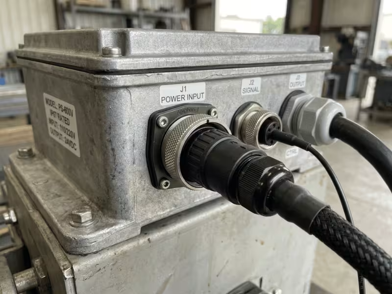
The connector is often the weakest link in a sealed box. Sealed circular connectors, like M12 types, lock, seal, and resist vibration far better than a loose plug. Match every cable gland to the enclosure rating. A well-sealed box loses its protection the moment a gland leaks.
Reliability, Lifetime, and What the Data Sheet Does Not Tell You
A supply that runs cool today can still fail years early. The data sheet won’t warn you, so here’s what actually shapes its life.
Capacitors are the first to go, and heat drives it. A rough rule holds: every 10°C rise roughly halves a capacitor’s life. Run a unit 20°C hotter than it needs, and you can quarter the years it gives you. Baseplate temperature isn’t just a thermal number. It’s a lifetime number.
That big MTBF figure looks reassuring, but it’s only fair to compare when the test conditions match. One vendor quotes it at 25°C and half load. Another quotes it at 40°C and full load. The numbers look comparable. They aren’t. Before you trust an MTBF, find the temperature, the load, and the standard behind it.
Derating buys you years, not just safety. Run a unit at 70% of its rating instead of 100%, and every part inside runs cooler and lasts longer. The margin you leave on the table today is what keeps the supply alive in year five.
Capacitor type sets the ceiling. Electrolytic capacitors dry out over time, and heat speeds that up. Solid or polymer capacitors hold up far better under heat and cycling, though they cost more. For a sealed box that runs hot around the clock, the capacitor type inside often decides the real service life.
How to Evaluate a Sample Before Full Production
A sample is your one chance to catch problems before they multiply across a production run. Test it hard, in the real enclosure, before you commit.
Ask the vendor for three things before the sample even ships: the derating curve with the baseplate axis marked, thermal resistance data from junction to baseplate, and full test reports from an independent lab. If a vendor stalls on any of these, treat that as a warning.
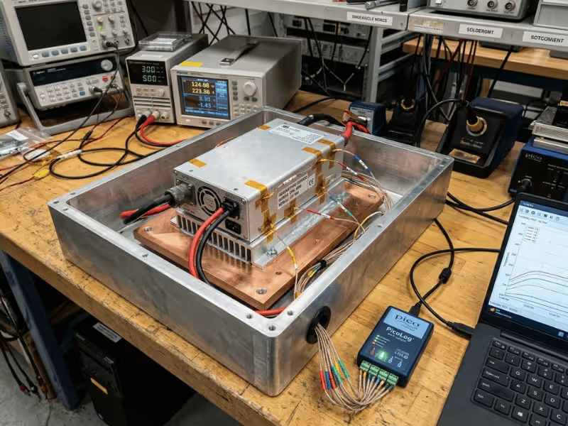
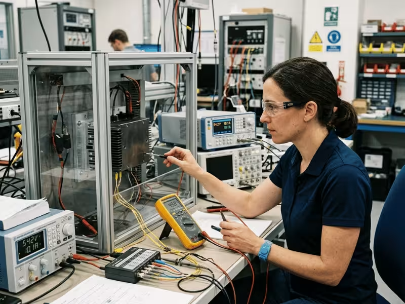
Bench numbers mean little. Mount the sample in your actual enclosure, or a faithful mock-up, and place thermocouples where the heat tells its story:
- On the baseplate, right under the hottest components.
- On the mounting surface, just beside the joint, to catch contact losses.
- Inside the enclosure air, away from the unit, to read trapped ambient.
That baseplate-to-surface gap reveals whether your thermal path actually works.
Run three scenarios, not one. Cold start: power up at your lowest expected temperature and watch for a unit that won’t come alive. Hot soak: let the box reach worst-case temperature, load the supply fully, and log baseplate temperature until it stabilizes. Compare that reading against the derating curve. Full load: hold peak output and confirm the supply never trips thermal shutdown or sags below spec.
Finish with the details. Confirm the baseplate lands flat against the surface. Watch startup on a scope for clean voltage rise. Measure ripple under full load, not idle. Then scan the unit with a thermal camera after hot soak. Uneven hot spots point to poor mounting pressure or a weak interface.
Common Mistakes That Cause Thermal or Reliability Failures
The same errors sink good designs again and again. Each one is easy to dodge once you know where it hides.
- Buying on nameplate wattage alone. That headline number lives in a cool lab, not your sealed box. A 300W supply may deliver only 180W at your real baseplate temperature.
- Ignoring the mounting surface. It’s the last leg of the cooling path, not just a bracket. Bolt the unit to thin, painted, or warped metal, and the heat has nowhere to go.
- Assuming fanless means thermally safe. No fan does not mean no heat problem. The supply only works when heat has a real route out of the box.
- Over-buying IP rating. A fully potted unit runs hotter, costs more, and ships later. You pay for submersion protection an indoor box never needed.
- Skipping thermal validation. Bench numbers don’t tell you what happens in your enclosure. A field failure costs far more than a hot-soak test ever would.
- Comparing MTBF numbers blindly. Line up the temperature, load, and standard first, or you’re comparing nothing.
- Treating the thermal path as a mechanical job. The joint between baseplate and wall carries heat like a wire carries current. Torque it evenly, or a hot spot forms at the loose corner.
A Practical Selection Checklist
Run this list before you commit to any conduction cooled supply. It catches trouble long before it reaches the field.
What to Confirm | What to Check | Why It Matters |
|---|---|---|
Temperature range | Worst-case ambient and baseplate temperatures in the real enclosure | The baseplate number decides real output, not the lab rating |
Output power with margin | Load at your baseplate temperature, plus 20–30% headroom | Peak nameplate wattage vanishes once the unit heats up |
Thermal resistance budget | The full path from junction to ambient conducts well | A weak link anywhere chokes the whole cooling chain |
IP rating and corrosion | Rating matches the real threat; metals suit the atmosphere | Over-sealing traps heat; wrong metals corrode contacts |
Electrical specs and protections | Input range, hold-up, ripple, OVP, OCP, thermal shutdown | Dirty power and faults kill supplies that survive the heat |
Mechanical fit and connectors | Baseplate lands flat; sealed pass-throughs; vibration rating | A loose joint or leaking gland undoes a good design |
Standards and certifications | Independent test reports, not self-declared claims | Verified compliance protects the deployment and you |
Thermal validation | Hot-soak a sample in the actual enclosure | Bench numbers never predict a sealed box in the sun |
Clear all eight, and the supply will run within its limits for the life of the deployment.
FAQs
What is a conduction cooled power supply?
It’s a supply that moves heat through metal instead of air. Heat travels from the hot components, into a baseplate, then into whatever surface you mount it against. No fan, no vents. That’s what lets it live in a sealed box where airflow was never an option. The tradeoff: it only works when the mounting surface actually carries the heat away.
Can I use a convection cooled supply inside a sealed box?
No. Convection depends on warm air rising off the unit and cool air taking its place. Seal the box, and that airflow stops dead. The heat has nowhere to go, so the supply overheats, derates hard, and fails early. For a sealed enclosure, you need a conduction cooled unit that hands its heat to metal, not to trapped air.
Do conduction cooled supplies need a heatsink?
Sometimes, but not always. The unit needs a surface that pulls heat away. A thick aluminum enclosure wall or a cold plate often does the job on its own. Add a heatsink when the mounting surface alone can’t shed your worst-case load. Size it for fin area and mass, and bond it with good interface material.
What is the difference between baseplate temperature and ambient temperature?
Ambient is the air temperature around the unit. Baseplate is the temperature of the metal surface where the supply mounts. In a sealed box, the baseplate runs well above ambient. This matters when you read a derating curve, since some curves plot against ambient and some against baseplate. Match the axis to the temperature you can actually measure.
How much does derating reduce output power?
More than most people expect. A supply holds full power only up to a set baseplate temperature, often around 50°C. Above that, output drops in a straight line. A 300W unit might deliver just 180W at 70°C baseplate, a 40% cut. Always read your worst-case baseplate temperature off the curve, then check the real output there.
What thermal interface material should I use?
Match it to the gap. Thermal pads suit flat, even surfaces and give repeatable results. Thermal paste fills thin gaps and conducts better, but needs a flat surface and can get messy. Gap fillers handle uneven surfaces or larger tolerances. Check flatness first, then pick the material that bridges your actual gap. For sensitive gear like medical power supplies, get the interface spec confirmed with the vendor early.
Are conduction cooled supplies more expensive than fan cooled ones?
Often yes, up front. Rugged baseplates, sealing, and higher-grade components cost more than a fan and a vented case. But look at the total cost. Fans need cleaning and replacement, and a fan failure in a remote box means a site visit and downtime. A conduction cooled unit has no moving parts to wear out, so the lower maintenance usually closes the gap over a long deployment.
How do I test whether a conduction cooled supply will stay cool enough?
Test the sample in your real enclosure, not on the bench. Place thermocouples on the baseplate under the hottest parts, on the mounting surface beside the joint, and in the trapped enclosure air. Run a hot soak: let the box reach worst-case temperature, load the supply fully, and log the baseplate reading until it stabilizes. Compare that number against the derating curve.
Wrapping It Up
Choosing a conduction cooled supply follows a clear order. Get the sequence right, and the rest falls into place.
Start with the thermal path. Trace where the heat goes before you look at anything else. Then read the derating curve at your real baseplate temperature, not the lab number.
Next, confirm the environment, the electrical specs, and the mechanical fit all match your enclosure. Each one can undo a good thermal design on its own. For guidance on matching a supply to specific deployments, browse real application scenarios before you commit.
Then validate a sample in the actual box. Hot-soak it, load it, and read the baseplate. This step is required, not optional.
Here’s the truth after years on the bench: the best conduction cooled power supply isn’t the one with the highest wattage on paper. It’s the one that stays within its thermal limits in the real enclosure.