A current of about 10 µA sounds tiny. If it flows straight through cardiac tissue, though, it can trigger ventricular fibrillation. Put that same current on intact skin, and the patient never notices it.
That gap shapes every medical power supply decision. I see engineers make two costly mistakes again and again.
Some under-specify. They pick a supply that looks fine on paper, then fail leakage testing late in the project.
Others over-specify. They pay for isolation and filtering their device never needed.
Both mistakes cost time and budget.
This guide shows how applied part type, grounding scenario, and use environment determine whether ultra-low leakage is mandatory, helpful, or wasted money when you choose a medical power supply.
Why Leakage Current Is a Bigger Deal in Medical Equipment
Every mains-powered device leaks a little current. In a laptop, nobody cares. In a patient monitor, that same trickle can decide whether your device passes certification or harms someone.
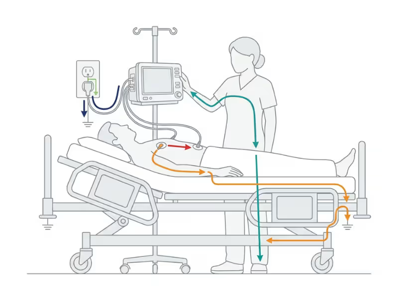
When I review a new medical design, I start with one question: where can the current go? Four paths matter, and not all of them depend on the power supply.
The Four Leakage Paths That Matter
- Earth leakage current flows down the protective earth conductor. The power supply’s Y-capacitors and EMI filter drive most of it.
- Touch current flows from the enclosure through a person to earth. It turns critical when the earth connection breaks, or when the device has no earth at all (Class II).
- Patient leakage current flows from the applied part through the patient to earth.
- Patient auxiliary current flows between applied parts through the patient, such as between two ECG electrodes.
Here’s the point I stress with every client. The power supply dominates the first two paths. The last two depend mainly on the isolation barrier between the applied part and everything else.
An ultra-low leakage supply helps, but it can’t rescue a poorly isolated applied part. If your ECG front end lacks proper isolation, a better PSU won’t save your test report.
Why the Single-Fault Condition Changes Everything
Commercial IT gear under IEC 62368-1 can allow protective conductor current up to 3.5 mA. That standard assumes healthy users with intact skin and a working ground.
Medical equipment plays by stricter rules. It must stay safe even under a single fault, such as a broken earth wire.
Picture what happens then. The earth leakage loses its safe path. It reroutes through whatever touches the chassis, and that might be a patient.
That patient may be unconscious and unable to pull away. Gel, fluids, or broken skin may lower their skin resistance. A catheter or lead may give the current a direct route to the heart.
A leakage level that seems harmless in an office can turn dangerous at the bedside. That’s why medical limits sit so far below ITE limits.
IEC 60601-1 Leakage Limits at a Glance
Numbers settle arguments faster than opinions. Before you compare any power supply datasheet, you need to know the limits your device must actually meet. Here’s the table I keep pinned above my desk.
The Limits Side by Side
Two terms run through every row:
- NC (normal condition) means the device works as designed, with all protective measures intact.
- SFC (single-fault condition) means one protective measure has failed, such as an open earth wire or an interrupted supply conductor.
IEC 60601-1 (3rd Ed.) Leakage Limits in µA
Current type | NC / SFC | Type B | Type BF | Type CF |
|---|---|---|---|---|
Earth leakage | NC / SFC | 5,000 / 10,000 | 5,000 / 10,000 | 5,000 / 10,000 |
Touch current | NC / SFC | 100 / 500 | 100 / 500 | 100 / 500 |
Patient leakage (AC) | NC / SFC | 100 / 500 | 100 / 500 | 10 / 50 |
Patient leakage (DC) | NC / SFC | 10 / 50 | 10 / 50 | 10 / 50 |
Total patient leakage (AC) | NC / SFC | 500 / 1,000 | 500 / 1,000 | 50 / 100 |
Mains on applied part | SFC | — | 5,000 | 50 |
Always check these figures against the latest edition, amendments, and any national deviations that apply to your target markets.
Two Things the Table Won’t Tell You
Look at the earth leakage row first. The 3rd edition relaxed it to 5 mA, and many engineers stop reading there. That’s a trap.
National deviations can be stricter. In the US, ANSI/AAMI ES60601-1 sets a tighter bar. So most manufacturers still design to about 300 µA earth leakage to cover every major market with one product. That’s exactly why “<300 µA” shows up on so many medical PSU datasheets. It’s not a random number. It’s a passport.
Now look at the Type CF column. For AC patient leakage, CF limits sit 10 times tighter than B and BF: 10 µA instead of 100 µA in normal condition. Total patient leakage follows the same pattern.
That tenfold gap is the reason this whole article exists. A supply that sails through a BF design can sink a CF one.
Type B, BF, and CF: Classifying Your Device
The applied part classification drives almost every leakage decision that follows. When a client sends me a power supply question, I ask for their applied part type before I look at a single datasheet. Once you know B, BF, or CF, half the spec writes itself.
What Each Classification Means
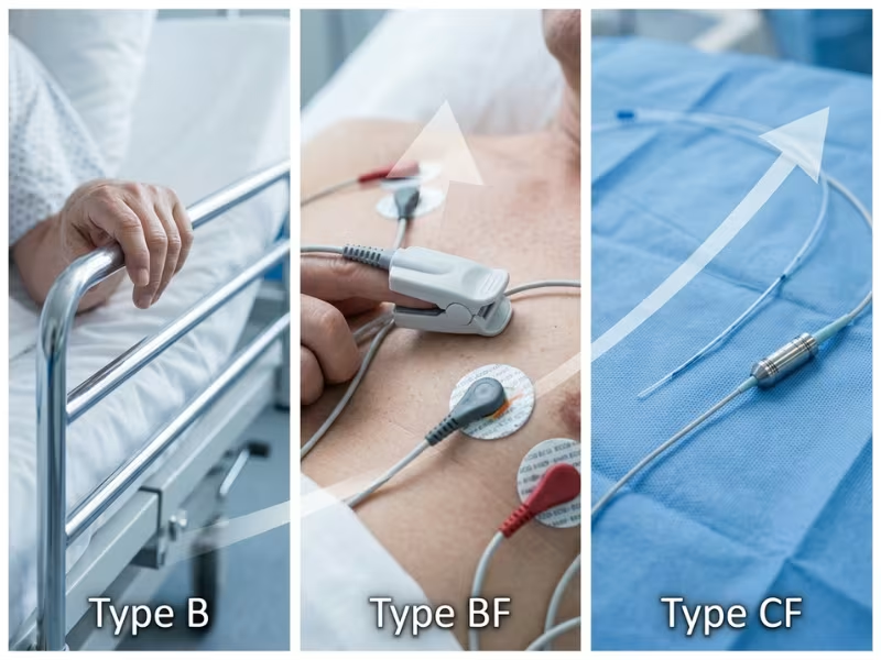
Think of the three types as a ladder. Each step up brings the applied part closer to the heart and puts more isolation between the patient and mains.
Type B is the bottom rung. The applied part may connect to earth, so it doesn’t float. Patient contact is non-cardiac and often incidental, like a patient lying on a bed frame.
Type BF adds a floating applied part. The “F” means the patient circuit stays isolated from earth. The part makes real conductive contact with the body, but it has no direct path to the heart.
Type CF sits at the top. It also floats, but with the highest isolation and the tightest leakage limits. You need CF when the applied part can touch the heart directly, through a catheter or an intracardiac lead.
Watch for one more variant: defibrillation-proof BF or CF. These applied parts must survive a defibrillator discharge while connected to the patient. That changes your isolation design. You need wider spacing, surge-rated parts, and often protection networks on the patient inputs. Plan for them early, because they eat board space fast.
Real Applications by Type
Definitions only go so far. Here’s how the classes map to real products I see in design reviews.
Applied Part Type by Application
Type | Typical applications | Why it lands here | Ultra-low leakage PSU? |
|---|---|---|---|
B | Hospital beds, exam lights, many dental chairs, some surgical lasers | No intentional patient circuit, or incidental contact only | Rarely needed |
BF | Patient monitors (surface ECG, SpO2, NIBP), infusion pumps, ultrasound probes, TENS and physiotherapy units, electrosurgical generators | Conductive body contact without a cardiac path | Helpful for tight system budgets |
CF | Intracardiac ECG, cardiac catheter and electrophysiology systems, invasive blood pressure transducers, some dialysis blood circuits | Possible direct conductive path to the heart | Strongly recommended |
A few patterns stand out.
Type B devices rarely justify an ultra-low leakage supply. A general medical-grade unit with solid earth leakage numbers usually covers you.
BF is where judgment comes in. A standalone infusion pump can live happily with a standard medical supply rated under 300 µA. Put that same pump on a cart with three other devices, though, and the shared leakage budget gets crowded fast. That’s when a lower-leakage supply earns its price.
CF leaves little room for error. With a 10 µA patient leakage limit in normal condition, every microamp counts. I push CF clients toward ultra-low leakage supplies from day one and have them pair those supplies with a well-isolated front end. The supply lowers the baseline, and the isolation barrier does the rest.
The Classification Comes From the Risk File, Not the Product Category
Here’s a mistake I catch often. An engineer assumes their device type fixes the classification. It doesn’t. Your risk analysis decides it, based on how the applied part actually touches the patient.
Take external defibrillators. A unit that uses surface pads is typically defibrillation-proof BF. Use internal paddles on an exposed heart, and you need CF-level protection. The product category stays the same, but the classification changes.
Classification also belongs to each applied part, not the whole device. One patient monitor can carry a BF SpO2 input and a CF invasive pressure input side by side.
So specify your power supply for the strictest applied part in the box. If one input is CF, the whole power architecture must support CF limits, even if every other port is BF.
Where the Leakage Budget Gets Tight
A device that passes on the test bench can still fail at the bedside. The limits stay the same, but the real-world setup changes how much leakage you can afford. These four scenarios cause most of the late-stage surprises I help clients sort out.
Multi-Device Carts and ME Systems
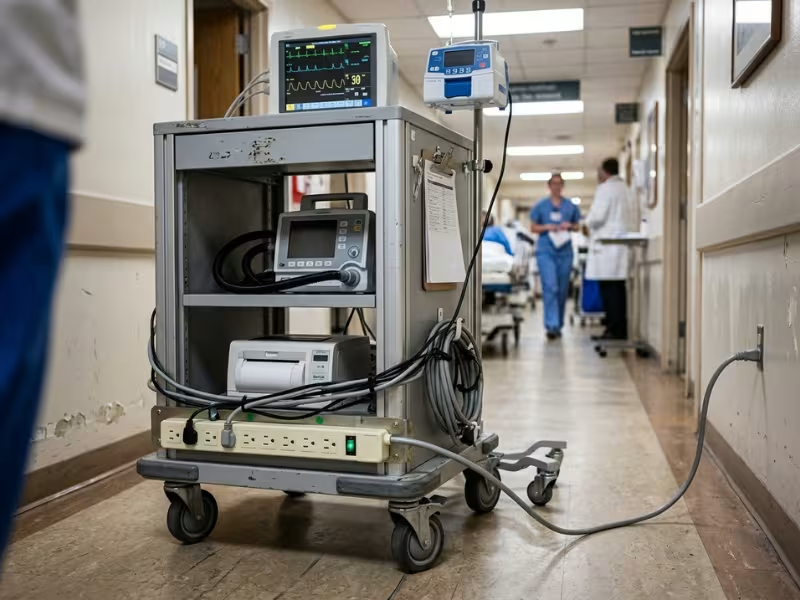
Picture a cart with a patient monitor, an infusion pump, a ventilator, and a printer. All four plug into one power strip, and each one leaks into the same shared earth.
IEC 60601-1 Clause 16 treats that cart as one ME system. The combined touch current must stay within limits. If the strip loses its earth, the system touch current in single fault can’t exceed 500 µA.
Now do the math. Four devices at 200 µA each add up to 800 µA. Every unit passed on its own, yet the cart fails.
What to specify: ultra-low leakage supplies under 100 µA, or an isolation transformer for the whole cart.
Home Healthcare and Class II Devices
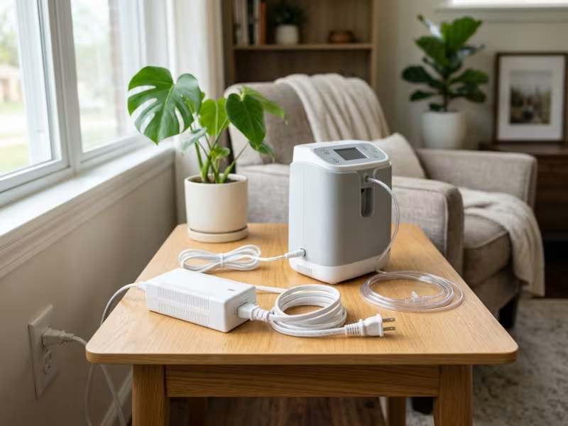
Home-use and portable applications take the setup out of your hands. IEC 60601-1-11 assumes lay users, two-prong outlets, old wiring, extension cords, and no biomedical engineer down the hall. In short, you can’t count on earth.
Class II adapters have no earth path at all. Every microamp of leakage becomes touch current, and the standard caps it at 100 µA in normal condition. No earth wire soaks up the excess. The user’s hand becomes the return path.
What to specify: Class II 2×MOPP adapters with low touch current. Many carry a rating of 100 µA or less. The best sit well under it, which leaves room for the rest of your circuit.
Battery-Powered and Mobile Equipment
Battery power feels like a safe escape. On battery alone, the device has no mains leakage path. But real users charge devices while patients stay connected, and that turns the charger into your leakage source.
Transport adds another layer. Ambulances run inverters and tie electronics to the vehicle chassis. Earth references shift with every vehicle and every setup, so you can’t predict where leakage will flow.
What to specify: a charger rated for patient-connected use, plus isolation on any internal DC/DC converters that feed applied parts. Don’t let the battery hide a weak barrier.
Wet Environments and Conductive Fluids
Fluids change the math. Dialysis, irrigation, hydrotherapy, and fluid-heavy surgery all lower body impedance. Saline on a drape or a spill under the table can also create conductive paths nobody drew on the schematic.
In these settings, a nominal BF device starts behaving closer to a CF risk profile. The label stays the same, but the patient’s exposure doesn’t.
What to specify: treat your leakage budget as if it were one class stricter. Then confirm that choice in your risk assessment, so auditors see the reasoning, not just the result.
How Ultra-Low Leakage Supplies Hit Their Numbers
A datasheet that says “<100 µA” didn’t get there by luck. Designers trade off filtering, isolation, and grounding to reach that figure. Once you know where leakage comes from, you can read any spec sheet with a sharper eye.
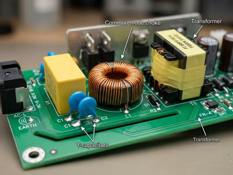
Y-Capacitors: The Main Leakage Source
Y-capacitors sit between line/neutral and earth. Their job is to shunt common-mode noise to ground. That means they leak by design.
You can estimate that leakage with one formula: I = 2πfCV.
Take a 4.7 nF Y-cap at 264 VAC and 60 Hz:
I = 2π × 60 × 4.7 nF × 264 V ≈ 470 µA
Swap in a 470 pF cap, and leakage drops to about 47 µA. Cut the capacitance tenfold, and you cut the leakage tenfold.
So why doesn’t every supply use tiny Y-caps? Because those caps do real work. Shrink them, and common-mode filtering weakens. Your EMI margin under IEC 60601-1-2 shrinks with it.
Good designers compensate in three ways:
- Larger common-mode chokes block noise before it needs a path to earth.
- Multi-stage filtering spreads attenuation across several smaller steps.
- Careful transformer shielding stops noise from coupling across the barrier.
None of this comes free. Each fix adds size and cost, and some trim a bit of efficiency.
2×MOPP Isolation
Y-caps explain most earth leakage. The isolation barrier decides how much reaches the output side.
2×MOPP means a 4,000 VAC primary-to-secondary withstand and 8 mm creepage at 250 VAC working voltage. Compare that with 1×MOPP at 1,500 VAC and 4 mm, or 2×MOOP at 3,000 VAC.
The transformer matters as much as the filter. Low inter-winding capacitance limits how much leakage couples across to the output. When I compare two 2×MOPP supplies, I ask the vendor for that capacitance figure. It often separates a good design from a great one.
One warning: 2×MOPP is a strength rating, not a leakage rating. It tells you the barrier won’t break down. It says nothing about how much current slips through. A supply can carry 2×MOPP and still leak 300 µA to earth.
Floating Outputs and Class II Design
Your grounding choices close the loop.
A floating secondary, with no connection to earth, stops earth-referenced leakage from reaching the output.
Class II designs go further and remove the earth altogether. That solves one problem but creates two more. All leakage now shows up as touch current, so every microamp counts against the 100 µA limit. And without an earth path, the EMI filter loses its usual dumping ground. Expect tighter layout work and smarter filtering to pass emissions.
Comparing Power Supply Options
Once you know your limits, the shortlist gets much shorter. When you compare power supply products for patient-connected equipment, most projects come down to three tiers, and each one solves a different problem. Here’s how I lay them out when a client asks where the budget should go.
Standard vs. Medical vs. Ultra-Low Leakage Supplies
Attribute | Standard ITE | General medical-grade | Ultra-low leakage medical |
|---|---|---|---|
Typical earth leakage | 0.5–3.5 mA | <300 µA | <100 µA (best <10 µA) |
Isolation | Basic or reinforced (IEC 62368-1) | 2×MOOP or 1–2×MOPP | 2×MOPP |
Certifications | IEC/UL 62368-1 | IEC 60601-1, ES60601-1 | IEC 60601-1, ES60601-1, often 60601-1-11 |
Suitable for | Non-patient devices in non-patient areas | Type B, most BF | CF, home use, ME systems, tight BF budgets |
EMI margin | Generous | Good | Tighter; may need system filtering |
Relative cost* | 1× | ~1.3–2× | ~1.5–3× |
Cost multipliers are indicative. Real figures shift with power level, volume, and vendor.
Read the EMI row as closely as the leakage row. As leakage drops, the supply leaves less filtering headroom for the rest of your design. Many teams miss that hidden part of the price tag until EMC testing.
The tier is only half the decision. Form factor shapes leakage, certification effort, and thermal design just as much.
External adapters keep mains and the main isolation barrier outside your device. Your enclosure only sees low-voltage DC, which makes certification much simpler. That’s why I steer most home-use and Class II designs this way.
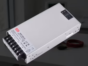
Open-frame embedded supplies give you the smallest footprint and the lowest cost. The catch is that your layout and enclosure now decide the final leakage and EMI numbers. A clean datasheet won’t survive a sloppy chassis, so plan to test inside your actual housing.
Enclosed supplies deliver more predictable performance. The housing adds shielding and makes thermal management easier. You pay for that in volume, so confirm your space budget early.
A Practical Decision Framework
Everything so far comes down to one choice: which supply goes on your bill of materials. When a client calls me mid-design, I walk them through the same short sequence. It takes about ten minutes and can save weeks of retesting.
Five Questions to Answer Before You Specify
Answer these in order. Each answer narrows the field before you open a single datasheet.
- What is the strictest applied part type in the device: B, BF, or CF? Your strictest applied part sets the leakage ceiling for the whole power architecture.
- Is the device Class I (earthed), Class II, or internally powered with a charger? Grounding decides whether leakage flows safely to earth or lands on the user as touch current.
- Where will it be used: hospital, clinic, home, or vehicle? Hospitals offer verified earth and trained staff. Homes and ambulances offer neither.
- Will it operate as part of an ME system or on a shared power strip? Leakage adds up across every device on a cart, so a unit that passes alone can still sink the system.
- What is your leakage budget? Subtract the PSU’s contribution from the limit, and see what remains for the rest of the circuit.
That last question trips up the most people. Say you build a Class II home device with a 100 µA touch current limit. You pick an adapter rated at 75 µA. That leaves just 25 µA for your cables, enclosure, and electronics. It also wipes out the 30–50% field margin I always recommend.
Write your answers into the requirements document. Your test lab and auditor will ask for that reasoning later.
Decision Matrix
With those five answers in hand, find your row below. This table reflects what I recommend on most of the projects I review.
Scenario | Recommended supply |
|---|---|
Type B, hospital, standalone | General medical-grade (2×MOOP acceptable) |
Type BF, hospital, standalone | Medical-grade 2×MOPP, <300 µA |
Type BF on a multi-device cart | Ultra-low leakage, <100 µA |
Any type, home use / Class II | Class II 2×MOPP adapter, low touch current, 60601-1-11 |
Type CF | Ultra-low leakage 2×MOPP, plus isolated applied-part circuitry |
Wet or fluid-heavy environment | Treat as one class stricter |
Two rows need a quick note.
For Type CF, the supply only lowers the baseline. Your isolated front end does the heavy lifting on patient leakage. Budget for both from the start.
For wet environments, document the stricter choice in your risk file. A BF device used in dialysis should carry a CF-level budget, and your file should explain why.
When Ultra-Low Leakage Is Overkill
A standalone Type B device in a hospital with verified earth rarely benefits. A good general medical-grade supply already sits well under the limits, and the device has no floating patient circuit to protect.
The real cost goes beyond the unit price. Tighter EMI margins can force extra filter parts onto your board and add rounds of EMC testing. I’ve seen teams spend more on retests than they ever gained from the “safer” supply. Match the supply to the risk, and put the savings where your device actually needs them.
Three Misconceptions That Cause Failed Tests
Most leakage failures I see don’t start in the lab. They start early, with assumptions nobody questions while the supply is still cheap to change. These three come up on project after project.
“Medical-Grade Means It Works for Any Medical Device”
The claim: If the supply carries an IEC 60601-1 certificate, you’re covered.
The reality: “Medical-grade” spans a wide range of designs. A 1×MOPP supply with 300 µA earth leakage carries full certification. Yet it can still push a CF device or a four-device cart past its limits. The certificate proves the supply is safe on its own. It says nothing about how it behaves inside your system.
The fix: Ignore the label and check the numbers. Compare the MOPP rating and leakage figures against your strictest applied part and your real-world setup.
“Battery Power Eliminates Leakage Concerns”
The claim: No mains cord means no leakage problem.
The reality: Users charge devices while the leads stay on the patient. Internal DC/DC converters without proper isolation can tie the applied part to other circuits. Capacitive coupling between the board, enclosure, and patient still opens small current paths. Any one of these can fail a test.
The fix: Measure leakage while charging, with patient cables attached. Specify a charger rated for patient-connected use and isolated converters on every rail that feeds an applied part.
“Lower Leakage Is Always Better”
The claim: If 100 µA is good, 10 µA must be better.
The reality: Over-specifying costs more than the unit price. Fewer vendors make ultra-low leakage supplies, and lead times can stretch. Smaller Y-caps also shift the EMI burden onto your board. That can mean extra filter parts and more EMC test rounds.
The fix: Match the requirement, and don’t exceed it blindly. Build your leakage budget, add a sensible field margin, and choose the supply that meets it. Put the money you save into the parts of the design that actually carry the risk.
Testing, Documentation, and Spec Sheet Checks
A leakage figure means little until you know how someone measured it. Before I trust any datasheet, I check the test method, the conditions, and the paperwork behind the number.
How Leakage Is Measured
IEC 60601-1 Clause 8.7 defines a measuring device (MD) network. This small resistor-capacitor circuit mimics the impedance of the human body. It also weights the reading by frequency, much as the body responds to current.
Labs test at 110% of rated mains voltage. They measure under normal condition and single-fault condition, and they reverse supply polarity to find the worst case.
Many engineers miss one detail. Leakage scales with voltage and frequency. A supply tested at 230 V / 50 Hz will leak more at 264 V / 60 Hz. Confirm that the datasheet’s test conditions match your worst-case market.
Why Field Results Differ From Lab Results
A clean lab number rarely survives the real world unchanged. Cable routing adds stray capacitance. Your enclosure couples current to the chassis. Attached peripherals, like printers or USB devices, bring their own leakage. Y-caps also drift as they age.
So leave a 30–50% margin below the limit. If your touch current limit is 100 µA, aim for 50–70 µA in your own tests.
Spec Sheet Checklist
Run through this list before you request samples:
- Earth leakage and touch current: Find the test voltage and frequency, not just the headline figure.
- MOPP/MOOP rating and isolation diagram: The diagram shows which barrier carries which rating.
- Applied part compatibility claim: Check whether the vendor states BF or CF suitability, and on what basis.
- Certificates: Ask for IEC 60601-1 and ES60601-1, plus 60601-1-11 for home use. A full CB report saves your test lab hours.
- 60601-1-2 EMC test data: Ask whether the vendor tested the supply standalone or in a reference system. Standalone results won’t predict your device.
- Operating altitude: Creepage and clearance requirements change above 2,000 m, so confirm the rating for high-altitude sites or air transport.
FAQs
What leakage level counts as “ultra-low” for a medical power supply?
Most suppliers use “ultra-low” for earth leakage under 100 µA, and the best reach below 10 µA. A general medical-grade supply usually sits under 300 µA. Check the test voltage and frequency behind any figure. A number taken at 230 V / 50 Hz looks better than one taken at 264 V / 60 Hz.
Can I use a standard medical-grade power supply in a Type CF device?
Sometimes, but it’s a risky bet. Your isolated front end controls patient leakage, yet CF allows just 10 µA in normal condition. Every microamp that couples through from the supply eats into that margin. I steer CF teams toward ultra-low leakage 2×MOPP supplies from the start.
How many MOPPs does a patient-connected device need?
Two. You need 2×MOPP between mains and any applied part. The simplest route is a 2×MOPP supply with 4,000 VAC withstand and 8 mm creepage. You can also split it, with 1×MOPP in the supply and 1×MOPP in the patient circuit. That approach shifts more test work onto your board.
Does a battery-powered device still need a low leakage charger?
Yes, if anyone can charge it while a patient stays connected. Once that happens, the charger becomes your leakage source. Specify a charger rated for patient-connected use, or add an interlock that blocks charging during patient connection. Either way, record the choice in your risk file.
Why do smaller Y-capacitors make EMI compliance harder?
Y-caps give common-mode noise a short path to earth. Shrink them, and more noise escapes down the power cord as conducted emissions. Designers fight back with bigger chokes, extra filter stages, and better transformer shielding. Each fix adds size and cost, and your system may end up with a thinner EMI margin.
How does IEC 60601-1-11 change power supply requirements for home use?
It assumes lay users, two-prong outlets, and no reliable earth. That pushes designs toward Class II 2×MOPP adapters, where all leakage becomes touch current capped at 100 µA in normal condition. It also raises demands for ingress protection, drop resistance, and wider environmental ranges. Ask vendors for 60601-1-11 test evidence.
Ultra-low leakage isn’t something you add out of habit or caution. Your applied part type, grounding scenario, and system configuration set the real requirement, so let those numbers drive the choice.
Here’s my verdict. CF devices, home-use Class II devices, and multi-device carts are where ultra-low leakage pays for itself. For standalone Type B equipment in a hospital, a general medical-grade supply is usually the smarter buy.
Whatever you build, create a leakage budget early in the design. Then ask your supplier for test data at your worst-case voltage and frequency, not just the headline figure. That one request can save you from a failed test months later.