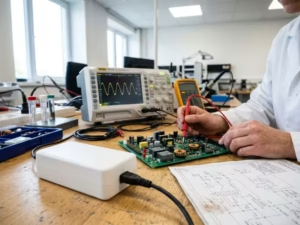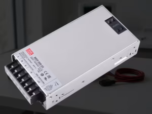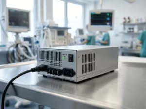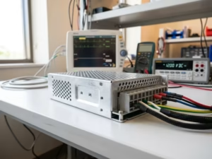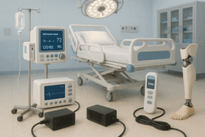
Many engineers assume a DC-DC converter for medical devices just needs to hit the right voltage. The real challenge is everything around that voltage. In medical equipment, the converter shapes your safety margins, your signal integrity, and your path to compliance.
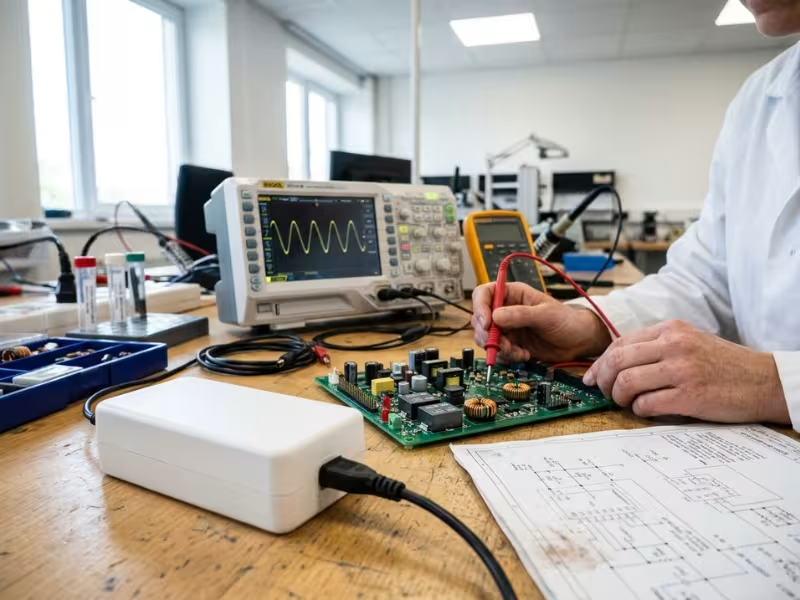
I have worked on power designs for patient monitors, portable diagnostic tools, and other medical device applications. I see the same pattern again and again. A design runs fine on the bench. Then it fails EMC testing, the isolation barrier falls short, or the enclosure overheats once the lid goes on.
Each failure sends the team back to layout, sourcing, or documentation. Certification slips, and the launch date moves.
This guide follows the selection path I use on real projects:
- Define what your device actually needs
- Match those needs to the right power architecture
- Verify the risks before they turn into test failures
Why DC-DC Converter Choice Matters More in Medical Devices
In consumer electronics, a slightly noisy or warm converter rarely hurts anyone. In medical equipment, the same flaw can reach a patient, distort a reading, or stall your submission.
Medical Devices Leave Less Room for Error
Many medical devices touch the patient directly. Electrodes, probes, and sensors create a path between your circuit and a human body. That makes the isolation boundary one of the most important lines on your schematic.
Leakage current adds pressure. IEC 60601-1 sets tight limits for patient-connected circuits, and CF applied parts with cardiac contact face the strictest ones. A converter with high barrier capacitance can push you past those limits, even when the rest of the design looks clean.
Noise is the next hurdle. ECG signals sit around 1 mV, and EEG signals drop to tens of microvolts. A few millivolts of switching ripple can bury the data your device exists to capture.
Heat finishes the list. Medical enclosures tend to be small, sealed, and fanless. A converter that wastes even one watt has nowhere to send that heat.
A Poor Converter Choice Creates Problems Later
I often hear teams say, “We can swap the converter later.” In medical design, that rarely works. A weak choice shows up downstream as:
- EMC failures under IEC 60601-1-2, fixed with late filters, shielding, or a board spin
- Analog contamination, as ripple couples into amplifiers and ADCs
- Production drift, when loose tolerances turn into yield losses
- Documentation gaps, which force retesting and risk file updates
This isn’t a component swap. It’s a system risk decision. The right converter surfaces risk early, while fixes stay cheap.
Start Here: Define the 6 Requirements That Actually Drive Selection
Before I open a single datasheet, I ask clients six questions. Their answers narrow the field faster than any parametric search.
1. Input Range: Know What Your Source Really Does
A medical device might run from a Li-ion cell, a 12V or 24V medical adapter, or a 24V or 48V cart bus. Don’t size the converter around the nominal number.
A Li-ion cell reads 3.7V on the label. It sits near 4.2V when full and drops toward 3.0V near cutoff. Heavy pulses pull it lower, and aging cells sag more. Adapters and buses bring their own surprises, such as cable drop, hot-plug spikes, and motor-driven dips.
My rule: define minimum input at end of battery life, coldest temperature, and peak load. Then add margin.
2. Output Rails: Plan for Peaks, Not Averages
Most teams get steady-state current right. Fewer catch the moments that break a design:
- Startup inrush from bulk capacitors, FPGAs, and processors
- Pulsed loads, like a radio jumping past 100 mA during transmit, or SpO2 LED drivers and pumps
- AFE sensitivity, where a 50 mV droop can appear as an artifact on an ECG trace
For each rail, I record steady-state current, peak current with duration, and maximum allowed deviation.
3. Efficiency and Heat: Measure Where the Device Runs
A datasheet may headline 94% efficiency at one load point. Your device may live somewhere else. A wearable might idle at 5 mA for hours, and light-load efficiency can fall to 70% without a power-save mode.
Turn efficiency into watts of loss. In a sealed, fanless plastic housing, 1–2W can raise internal temperature by 15°C or more. I set a thermal budget before picking parts, and every candidate must fit inside it.
4. Isolation: Decide If You Need It, and Why
This answer reshapes your architecture, so settle it early. Isolation can serve different jobs:
- Safety: patient-connected circuits may need means of patient protection (MOPP)
- Noise control: keeping digital and power-stage noise out of a sensitive AFE
- Ground loops: breaking current paths to connected equipment
- Partitioning: splitting the system into domains that are easier to test
Write down the reason for each boundary. A safety barrier brings specific creepage, clearance, and test voltage needs. A noise barrier may only need functional isolation with low barrier capacitance.
5. EMC and Noise: Build It In From Day One
The converter is often the loudest source on a medical board. Set your limits up front: allowable ripple per rail, frequency bands to avoid, and whether you need sync or spread-spectrum.
“Add a filter later” rarely works in medical design. Late filters eat board space, add heat, and can upset loop stability.
6. Lifecycle and Documentation: Plan for the Long Haul
Medical products often stay on the market seven to ten years or more. A converter that goes end-of-life in year three can force a redesign and a regulatory update.
Ask about PCN and EOL policies and second sources. Request the IEC 60601-1 CB report and isolation data during evaluation. I once watched one missing CB report hold up a submission for six weeks.
If two or three of these six items are still blank, hold off on comparing part numbers. The most common mistake I see isn’t picking the wrong part. It’s picking too early.
Do You Need an Isolated Converter?
This question changes your layout, your BOM, and your test plan. The answer depends on where each rail sits and what it connects to.
When a Non-Isolated Design Is Usually Fine
If a circuit doesn’t touch the patient and doesn’t cross into another ground domain, a simple buck or boost often works well. Picture a 12V rail feeding 3.3V logic, a 1.8V MCU core, and a 1.0V FPGA core. They share one ground, so isolation adds cost and heat with no benefit.
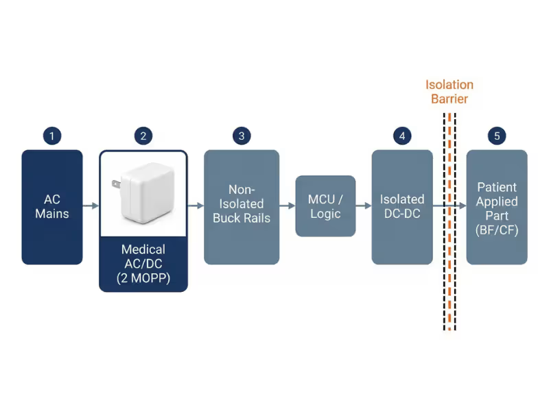
The same applies when a safety barrier already exists upstream. If a certified medical-grade AC/DC power supply provides 2 MOPP from mains, the rails behind it can often stay non-isolated. Check your insulation diagram, though. Mains isolation alone doesn’t make an applied part floating.
Efficiency favors this path too. A good synchronous buck reaches 90–95%, while many small isolated modules sit near 80–85%.
When Isolation Becomes the Safer Choice
I push clients toward isolation early in these cases:
- Patient-connected circuits: BF and CF applied parts must float from earth and other device parts. For CF parts, barrier capacitance matters as much as voltage rating.
- Sensitive analog front ends: ECG, EEG, and EMG signals suffer when processors, radios, or motor drivers share their ground.
- Different ground references: USB links to a PC, hospital networks, and nurse-call systems bring in outside grounds. I pair isolated power with isolated data here.
- Clear regulatory boundaries: a defined barrier with a certified converter makes your insulation diagram easier to defend.
Isolation Does More Than Pass Safety Review
Isolation is also a noise tool. An isolated supply with low barrier capacitance, often under 10 pF, blocks much of the common-mode path into patient leads. Standard modules with 50–100 pF can still pass plenty of high-frequency noise, so check that spec.
It also breaks ground loops that show up as 50/60 Hz hum. And splitting the system into patient, digital, and power domains makes each block easier to test and document.
A Practical Rule of Thumb
If your team is still debating isolation, you’re making an architecture decision, not comparing efficiency curves. Settle it with three documents side by side:
- Applied part classification: Type B, BF, or CF
- System insulation strategy: where each barrier sits and its MOOP or MOPP level
- EMC plan: which domains produce noise and which need protection
When they conflict, resolve that before you shortlist parts.
Which Converter Type Fits the Job?
With requirements and boundaries defined, picking a topology gets much easier.
Buck Converters for Logic Rails
A buck steps voltage down and handles most daily work: 3.3V logic, MCU and FPGA cores, and 5V interface power. Synchronous bucks often reach 90–95% efficiency.
Watch two details. Battery devices need a good power-save mode for light loads. But power-save shifts switching frequency with load, which can land noise in your signal band. Near an AFE, I often use forced-PWM mode or add an LDO.
Boost and Buck-Boost for Sagging Batteries
A boost raises a low input, such as a 2-cell alkaline pack to 5V, or drives LED strings for SpO2 sensors.
A buck-boost handles inputs that swing above and below the output. A Li-ion cell falling from 4.2V to 3.0V can’t hold a 3.3V rail through a plain buck. A buck-boost keeps it regulated and extends runtime. Ask vendors for ripple data near the transition zone, where input and output sit close.
Isolated Converters for Floating Domains
Isolated converters power BF and CF applied parts, isolated AFEs, and external ports. Flyback suits a few watts to tens of watts. Small push-pull modules handle 1–2W AFE power. Focus less on theory and more on what the barrier must deliver:
- Isolation rating: MOPP level, test voltage, creepage, working voltage
- Barrier capacitance: often the deciding spec for CF parts
- Regulation: many small modules are unregulated, so plan an LDO
- Efficiency at your load: often 75–85%, lower at light load
Multi-Stage Power Is Often the Real Answer
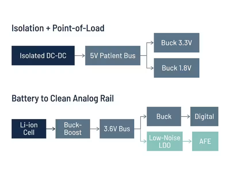
Real medical devices rarely run on one converter. The best designs I’ve reviewed chain stages, each doing one job well:
- Isolation + point-of-load: a certified isolated converter creates a 5V patient-side bus, and small bucks make 3.3V and 1.8V near each load
- Battery → intermediate bus → clean analog rail: a buck-boost feeds a 3.6V bus, a buck serves digital loads, and a low-noise LDO supplies the AFE
This split keeps safety, efficiency, and noise from competing inside one part.
Module or Discrete? Choose Based on Validation Burden, Not BOM Alone
Teams often frame this as a $12 module versus $3 of discrete parts. The better question: how much testing and risk can your team absorb before launch?
Why Modules Are Often the Lower-Risk Option
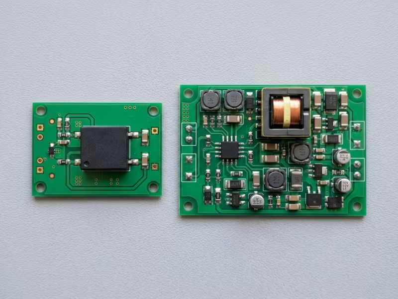
A certified module arrives with the transformer qualified, the barrier proven, and thermal behavior characterized. Your test lab reviews an existing CB report instead of testing a custom barrier. On one patient monitor project, that alone cut about two months from the safety schedule.
Strong vendors also supply creepage data, barrier capacitance, leakage figures, and reference EMC layouts. For teams without a dedicated power engineer, that support matters.
When a Discrete Design Makes Sense
I recommend discrete when several conditions line up:
- High customization, such as unusual outputs or frequency locked to your ADC clock
- Tight space in a wearable or slim handheld
- Real volume, where $4 saved across 50,000 units a year funds the extra validation
- Proven in-house skill in magnetics, loop compensation, safety spacing, and EMC
The last point matters most.
The Hidden Cost of “Cheaper” Power Design
Discrete usually wins on BOM. The project budget often tells another story:
- Rework from weak compensation or hot magnetics
- EMC remediation with repeat lab sessions
- Certification delays, where one failed hi-pot test can cost a quarter
- Sourcing risk from single-source custom magnetics
In medical projects, the lowest procurement cost is often not the lowest project cost.
How to Compare Candidate Converters Without Getting Misled by the Datasheet
Datasheets reflect kind conditions: 25°C, stable input, and an ideal evaluation board. I read them like an auditor.
Check Performance at Real Operating Points
Skip the headline number. Pull efficiency at 20%, 50%, and 80% load, and at your minimum and maximum input. A part that hits 93% at full load may drop to 78% at 20%.
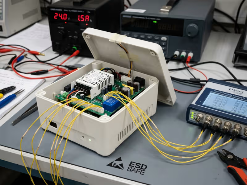
Then read the conditions under each graph. “25°C, natural convection” means an open bench, not a sealed housing. Some modules lose 30% of rated power by 70°C. When two parts look close, I test both in a closed box with thermocouples.
Pay Attention to Ripple, Noise, and Switching Behavior
A “50 mV p-p” ripple figure means little without the bandwidth limit and probe method. Then check:
- Fixed vs. variable frequency, and whether a SYNC pin exists
- Synchronous vs. asynchronous, since async diodes add loss and noise
- Spread spectrum, which helps EMC scans but can hurt sensitive measurements
- Adjustable soft-start to tame inrush
Review Protection and Fault Behavior
Every datasheet lists OVP, OCP, OTP, and short-circuit protection. What matters is how the part responds. Hiccup, constant-current, and latch-off modes each change how your device fails and recovers. A latch-off on an alarm circuit may need a documented recovery path.
Test startup corners yourself: pre-biased outputs, slow input ramps, and cold starts. I also keep continuous load under 70–80% of rating.
Evaluate Documentation and Supply Support
Before I approve a part, I ask for:
- The full IEC 60601-1 CB report, not just a logo
- MOOP/MOPP rating, working voltage, creepage, and clearance
- Leakage data and barrier capacitance
- EMC reports, including the filter used
- PCN notice period and last-time-buy terms
Read the report itself. A 2 MOPP rating at 250 VAC won’t cover conditions outside those limits.
Prefer Parts That Make Verification Easier
When two candidates score close, I ask: what would I need to prove if I chose this part? A converter with 2% lower efficiency but complete evidence can save months of verification.
Common Mistakes in Medical Power Design
Most troubled projects I review share these four habits.
Treating Medical Like Industrial With Extra Paperwork
Industrial converters often target around 1,500 VAC isolation. A 2 MOPP barrier at 250 VAC working voltage commonly needs about 4,000 VAC and roughly 8 mm creepage, depending on your insulation scheme. No document fixes missing hardware. I once saw a team learn this after building 200 pilot units.
Correct approach: map applied parts and insulation first, then choose converters rated for those limits.
Leaving EMC Until Layout Is Finished
Once layout locks, you can’t easily shorten a hot loop or move a converter away from patient cables. Bolt-on fixes add heat and cost. Issues that take an hour on a schematic can take six weeks after release.
Correct approach: set EMC limits with your power requirements and scan your first prototype.
Ignoring Thermal Derating in Sealed Housings
Inside a sealed case, local air can reach 50–60°C, where many modules deliver only 60–70% of rated output. As a rule of thumb, electrolytic capacitor life roughly halves for every 10°C rise. Skin-contact surfaces add another limit, often around 43°C for prolonged contact, depending on conditions.
Correct approach: measure internal temperature in a closed prototype early and derate from there.
Requesting Compliance Documents Too Late
Reports requested after design freeze bring surprises: an older standard edition, 1 MOPP instead of 2, or only a self-declaration.
Correct approach: request documents during shortlisting and drop parts with gaps you can’t close.
A Practical Selection Workflow
Here is the sequence I run on every medical power project. The order matters as much as the steps.
Step 1: Define Power Rails and Worst-Case Load
Build a rail table with voltage, steady-state current, peak current, duration, and allowed deviation. Stack the worst cases: lowest battery, coldest start, and a radio burst during a pump cycle.
Step 2: Decide Whether Isolation Is Required
Mark every rail on your insulation diagram. Note the reason for each barrier: safety, noise, or ground-loop control. A rail without a clear reason usually doesn’t need one.
Step 3: Screen by Safety and EMC Suitability
Drop parts that miss your MOPP level, leakage target, or barrier capacitance. Remove parts that switch near your signal band. I often cut 20 candidates to four in an afternoon.
Step 4: Compare Thermal and Efficiency at Real Conditions
Plot efficiency at your actual operating points and convert losses to watts. Drop any part that only fits your thermal budget with heavy derating.
Step 5: Review Documentation and Lifecycle Support
Read the CB reports, EMC data, and lifecycle commitments. Track vendor response time. A vague EOL policy is a valid reason to drop a strong part.
Step 6: Validate Early With Layout and Pre-Compliance Testing
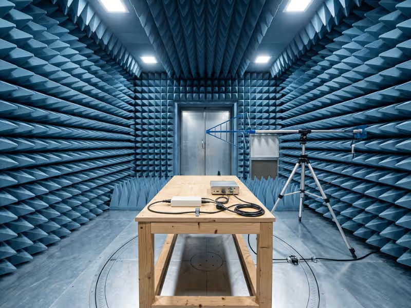
Build your first prototype on the vendor’s reference layout. Close the enclosure, log internal temperatures, run a pre-compliance scan, and probe ripple at the AFE input. Early validation moves faster when your supplier can also support EMC testing and verification. Fixes here take hours. After design freeze, they take weeks.
FAQs
What Is the Difference Between MOOP and MOPP?
MOPP protects patients, while MOOP protects operators such as clinicians and technicians. MOPP requirements are stricter because a patient may be unconscious, connected to electrodes, or unable to pull away from a shock.
In many 250 VAC designs, 2 MOOP calls for about a 3,000 VAC test, while 2 MOPP calls for about 4,000 VAC and roughly 8 mm creepage. Exact values depend on your insulation scheme and conditions. I size any barrier near the patient to MOPP, and default to MOPP when in doubt.
Can an Industrial-Grade Converter Be Used in a Medical Device?
Yes, but only when it doesn’t form part of the medical safety barrier. A common example is an industrial point-of-load buck behind a certified medical AC/DC supply that already provides 2 MOPP.
Typical industrial isolation falls well short of 2 MOPP, and barrier capacitance often runs too high for BF or CF parts. Confirm that the part has no safety role, fits your EMC plan, and has supply support that matches your product’s lifespan.
How Do I Choose Between Isolated and Non-Isolated Power?
Use isolation when a rail powers patient-connected parts, links to outside equipment, or feeds a noise-sensitive AFE. Otherwise, choose non-isolated for better efficiency, smaller size, and lower cost.
Write the reason next to every barrier on your insulation diagram. Your test lab will ask for it.
Are Certified DC-DC Modules Worth the Extra Cost?
Yes, in most medical projects. A certified module brings a CB report, rated MOPP level, leakage data, and often a reference EMC filter. Your test lab reviews that evidence instead of testing a custom barrier, which can save weeks.
At high volumes, or with strong in-house power expertise, discrete can pay off. Either way, confirm the CB report covers your standard edition, working voltage, and MOPP level.
Choose the Converter You Can Prove
The right DC-DC converter for a medical device rarely comes from a parametric search. It comes from the questions you answer first.
Start with your boundaries: input range, output rails and peaks, thermal budget, noise limits, and isolation barriers. Until those are clear, comparing part numbers is guesswork.
Then screen candidates against real conditions. Check efficiency at your load points, heat inside a sealed housing, and ripple at your analog front end. A single headline efficiency number won’t tell you how a part behaves in your product.
Finally, weigh what each option asks you to prove. On medical projects, I favor converters that are easy to verify, fully documented, and backed by long-term supply commitments. They may cost more per unit. By launch day, they usually cost less.