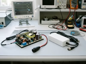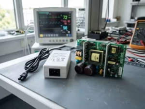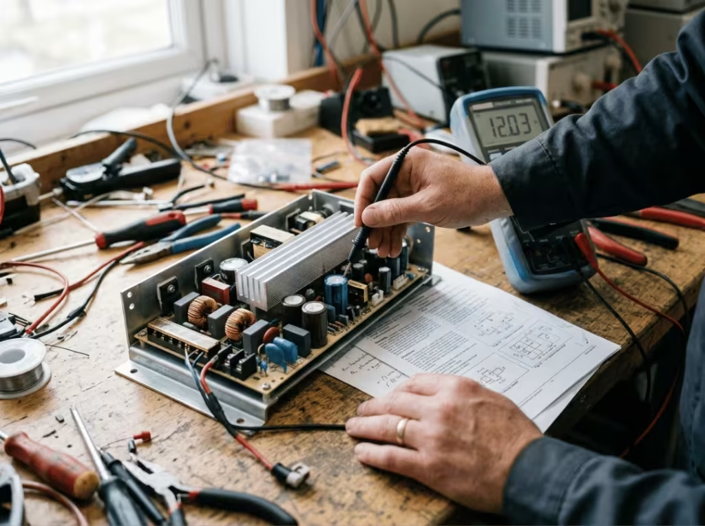
A power supply rated at 500 W does not necessarily deliver 500 W in your system. That number comes from a bench test under conditions your installation will rarely match. Raise the ambient temperature, restrict the airflow, drop the input voltage, or move the unit to a higher altitude, and the usable output falls below what the label promises.
Power derating is how you account for that gap. It is not a theoretical adjustment you apply for a safety margin on paper. It is part of selecting a supply that still works at the worst-case operating point, not just on the test bench. Skip it, and you ship a design that passes validation and then fails in the field under the exact conditions it was meant to survive.
This guide covers how to read a derating curve, how to calculate available output under real conditions, and how much margin to leave when you make the final selection.
What Power Derating Means in Power Supply Selection
Power derating is the reduction of a supply’s rated output to keep it inside safe limits under real operating conditions. You back off from the maximum so heat, altitude, or low input voltage don’t push internal components past their ratings.
Three terms carry most of the weight here:
- Rated output — the headline power figure, valid only under the datasheet’s stated conditions.
- Derated output — the actual power available at your worst-case operating point.
- Headroom — the margin you keep between your real load and the derated output.
You will also see terms like safe operating area (SOA) and combined maximum rating on datasheets. The SOA is the full envelope of voltage, current, and temperature where the device runs reliably. The combined maximum rating matters because you generally cannot hit two independent maximums at once — full output, maximum temperature, and minimum input voltage is not a condition most supplies will hold. Read those limits together, not in isolation.
Derating vs. Shutdown
These are not the same thing, and treating them as interchangeable leads to undersized designs.
Derating is a design decision you make before selecting the supply. Shutdown is a protection mechanism the supply triggers after a limit has already been crossed. Over-voltage and thermal shutdown prevent catastrophic damage, but they guarantee nothing about performance. If you lean on shutdown to cover an undersized supply, you get intermittent failures and dropouts at peak load. Derate correctly, and you never reach that point.
When Derating Becomes Necessary
Any condition that either raises internal temperature or reduces the supply’s ability to shed heat forces you to derate. The physics chain is short: a lower input voltage means a higher input current to maintain the same output power, which leads to greater conduction loss and more heat. Higher ambient temperature directly raises junction temperatures. Thinner air at altitude carries away less heat per unit of airflow. Each effect stacks on the others.
Ignore this, and the failure modes are predictable: overheated semiconductors and magnetics, degraded transformers that lose linearity and dump excess heat, thermal runaway, dropouts during load peaks, and shortened service life from sustained stress on every component.
The Conditions That Reduce Available Output
Five conditions cause most derating in practice. They are listed here roughly in the order a typical selection process encounters them.
Condition | Why output drops | What to check |
|---|---|---|
High ambient temperature | Junction temperatures rise toward their limit | Thermal derating curve |
Cooling method / airflow | Passive cooling removes far less heat than forced air | Convection vs. forced-air rating |
Low input voltage | Input current rises, increasing loss and heat | Input range and current limit |
High altitude | Thinner air carries away less heat | Altitude specification |
Enclosure and load profile | Trapped hot air and transient peaks add stress | System-level thermal behavior |
Thermal Derating
Thermal derating shows up in nearly every real design. As ambient temperature rises, junction temperatures within the supply rise with it. Past a certain point, the supply can’t hold full output without pushing those junctions beyond their rated limit, so available power drops. The thermal derating curve shows exactly where that starts and how fast output falls. Read it first for every supply you evaluate.
Cooling Method
The same supply usually carries two ratings — one for forced-air cooling, one for natural convection — and the gap is wider than most engineers expect. Forced air actively moves heat off the components. Natural convection relies on slow, passive airflow driven solely by a temperature difference. A 200 W supply with a fan may only deliver 140 W in a sealed, fanless enclosure at the same ambient conditions. If your design runs on convection, the convection rating is the only number that applies.

Input Voltage Derating
A supply’s job is to deliver watts. When the input voltage sags, it draws more input current to keep the output constant, which stresses the input stage and increases internal heat. This bites hardest in regions with low or unstable grid voltage, where line voltage can drop well below nominal. Design around your minimum expected input voltage, not the value printed on the datasheet cover.
Altitude Derating
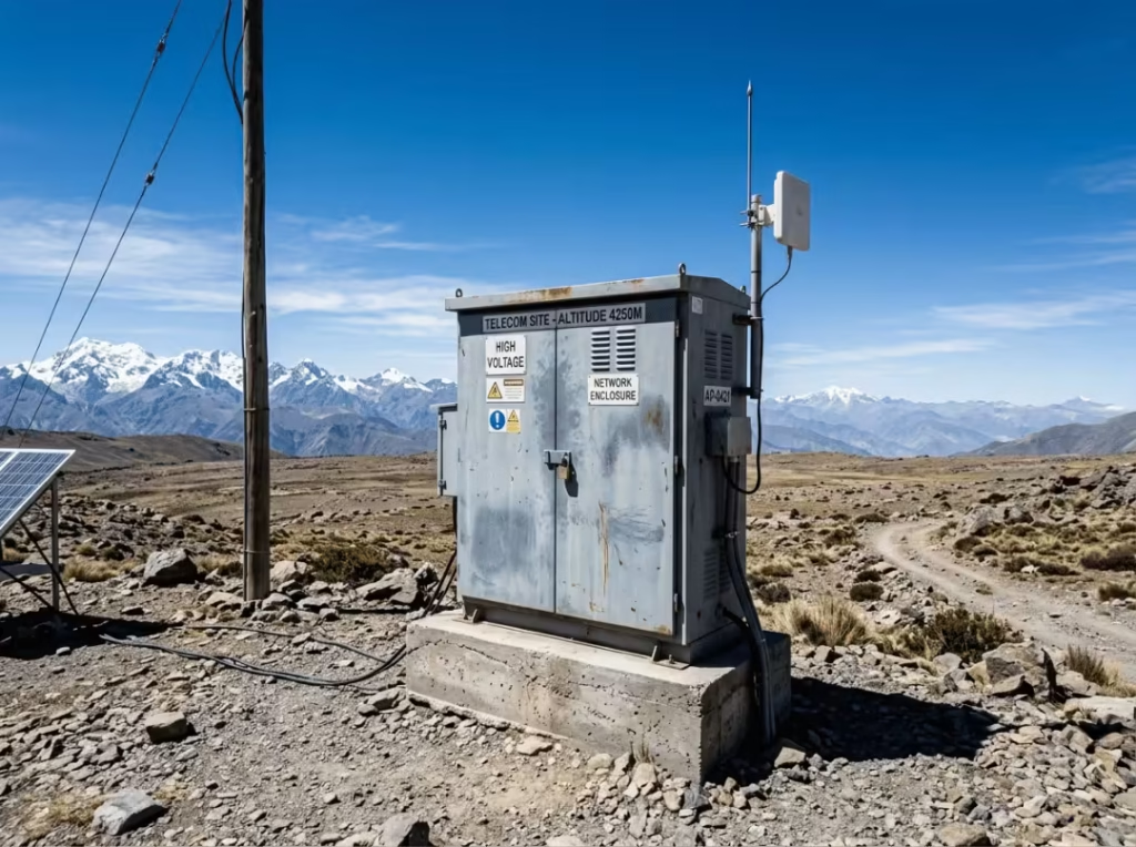
Air density drops with altitude, and thinner air moves less heat per cubic meter. Both forced-air and natural convection lose effectiveness as you climb. This is easy to miss when a system is designed at sea level and deployed at 3,000 meters or higher. Check the altitude spec, and confirm whether the supply’s fans can compensate before you close the design.
Enclosure and Load Profile
Free-air derating curves assume clean, unrestricted airflow. Real supplies sit inside enclosures that trap and recirculate hot air. A unit whose hot exhaust loops back into its own intake runs significantly hotter than the same unit in open air, and orientation makes this better or worse. Load profile matters too — startup inrush and transient peaks can briefly demand far more than the steady-state average. Size for the peak, not the average.

How to Read a Derating Curve
A derating curve plots temperature on the X-axis and available output power on the Y-axis. The shape has two regions: a flat section where the supply holds full rated output, and a declining section past the knee point where output falls as temperature rises, down to a maximum rated temperature beyond which operation isn’t recommended.
Reading the shape is the easy part. Reading it correctly is where selection succeeds or fails. Before you trust any curve, confirm what it actually describes:
- Which cooling condition does this curve assume? Many datasheets publish separate curves for forced air and natural convection. Using the forced-air curve for a convection design is the single most common derating error. If only one curve is shown, find the footnote that states the airflow condition — it is always specified somewhere.
- What mounting orientation and airflow direction does it assume? Curves are typically measured in free air with a defined orientation. Your enclosure and mounting will not match that, so treat the curve as a ceiling rather than a guarantee.
- If multiple curves are shown, which one is yours? Match the curve to your input voltage and cooling method. Supplies often derate more steeply at low line voltage — pick the curve for your minimum input, not the nominal one.
- Is the decline actually linear past the knee? Don’t assume. Some curves bend. Read the output at your exact worst-case temperature off the plotted line, not from an interpolation you sketched in your head.
- Check the table and footnotes, not just the graph. Tabulated data and footnotes often carry qualifiers — enclosure conditions, altitude assumptions, measurement standards — that the graph alone doesn’t show.

Worked reading: a curve flat to 55 °C that then declines to a hard stop at 70 °C. A worst-case ambient of 40 °C sits well inside the flat region, so you draw full output. A worst-case ambient of 65 °C sits deep in the decline — read the reduced output directly off the curve at 65 °C and design to that number. Once you cross the knee, the headline rating no longer applies. Treat everything past that point as a different, lower supply.
How to Calculate Power Derating Step by Step
This eight-step sequence moves you from system requirements to a validated selection. The order matters — jumping straight to the datasheet number before you’ve pinned your worst-case conditions is exactly how oversights become field failures.
- Define your load. Output voltage, current, and total power under full load. Include peaks, not just the steady-state average.
- Find your worst-case ambient temperature. The highest temperature the supply will ever see in its installed location — worst case, not average.
- Confirm the cooling method. Forced air, natural convection, liquid, or a combination. This determines which curve you read.
- Identify minimum input voltage. The lowest line voltage realistically present at the supply’s input terminals.
- Account for altitude, enclosure, and airflow. Every factor that limits heat removal belongs on the table now.
- Read available output from the correct curve at your worst-case operating point — not from the flat region.
- Apply headroom. Leave margin between your load and the derated output limit.
- Verify transients, startup, and fault conditions. Confirm the supply handles inrush, surges, and edge cases without tripping shutdown.
Altitude Derating: The Formula
Atmospheric pressure tracks altitude in a well-characterized way. At roughly 5 km above sea level, pressure falls to about 55% of sea-level pressure. Since air density and heat-carrying capacity are affected by pressure, cooling capacity drops by about 45%.
Worked example: a supply delivering 6.6 kW at sea level, applied at 5 km:
Available output ≈ 6.6 kW × 0.55 ≈ 3.6 kW
Fan-cooled supplies can offset part of this by spinning faster in thinner air, but the compensation is partial and not guaranteed. Verify against the datasheet’s altitude spec, and test on-site when the deployment altitude is unusual or exceeds the listed range.
Real-World Power Derating Examples
Three examples, each under a different constraint. Each ends with where the mistake usually hides.
Example 1 — Thermal Derating at High Ambient Temperature
Scenario: A system requires 12 kW of DC output in a 2U rack, air-cooled, with a maximum ambient temperature of 65 °C.
What the datasheet says: An air-cooled supply with a curve flat to about 55 °C is rated ~3,750 W per unit. Four units in parallel add up to 15 kW — comfortably above 12 kW.
Where engineers often misread it: They read the flat-region number and multiply. At 40 °C, that math holds. At the real 65 °C worst case, each unit sits deep in the decline zone.
Calculation:
Condition | Output per unit |
|---|---|
At 40 °C (flat region) | ~3,750 W (full rated) |
At 65 °C (derated point) | ~2,900 W |
Four units at 65 °C deliver ~11.6 kW — 400 W short of the requirement. The shortfall only appears when you evaluate at worst-case temperature.
Selection implication: When ambient conditions are high and output must be guaranteed, air cooling may not have sufficient margin. A liquid-cooled supply is limited by coolant temperature rather than by hot ambient air, so it has more headroom at elevated ambient temperatures. Use air cooling where conditions allow; switch to liquid when the ambient is punishing.
Example 2 — Natural Convection vs. Forced Air
Scenario: A design needs 160 W DC at a maximum ambient of 40 °C, with no forced airflow — natural convection only. The candidate supply is rated 200 W.
What the datasheet says: 200 W. On paper, that’s 25% headroom over the 160 W load.
Where engineers often misread it: They read the 200 W figure without checking which cooling condition it assumes. That number is the forced-air rating. There is a separate, lower convection rating further down the datasheet.
Calculation:
Cooling method | Output at 40 °C | Meets 160 W? |
|---|---|---|
Forced air | ~200 W | Yes |
Natural convection | ~140 W | No |
Under convection at 40 °C, the same supply holds only ~140 W — 20 W short.
Selection implication: For any passively cooled application, the convection rating is the only valid number. When it falls short, move to a higher-capacity supply whose convection curve covers your load at worst-case temperature. Don’t pad the forced-air figure and hope.
Example 3 — Altitude Derating
Scenario: A system needs 3.5 kW of DC output in a 1U rack, operating at up to 5 km altitude. A modular design allows three units per rack, rated 2.2 kW each — 6.6 kW combined at sea level.
What the datasheet says: 6.6 kW combined, nearly double the 3.5 kW requirement.
Where engineers often misread it: They compare the 3.5 kW load against the 6.6 kW sea-level rating, see a large margin, and stop. The rack never operates at sea level.
Calculation:
- Sea-level capacity: 3 × 2.2 kW = 6.6 kW
- Pressure at 5 km: ~55% of sea level → ~45% derating
- Derated capacity: 6.6 kW × 0.55 ≈ 3.63 kW
- Check: 3.63 kW > 3.5 kW required ✅
Cross-check from the requirement: 3.5 kW ÷ 0.55 ≈ 6.36 kW minimum sea-level capacity needed. Three units at 6.6 kW clear that threshold — but only just.
Selection implication: The design works at 5 km only because altitude derating was applied during sizing. Using the sea-level rating unmodified would have produced a system that would fail at the exact altitude at which it was built.
How Much Headroom Should You Leave?
Start with about 20% design headroom under standard datasheet conditions. That is a starting point, not a fixed rule. The right margin depends on how tightly you can control the operating environment and how much a failure costs.
Your worst-case ambient might sit at 50 °C for 99% of the year, but the 1% spike to 65 °C is exactly what the headroom absorbs. Size to 100% of the derated output, and you have nothing left for anything unexpected.
You can tighten the margin below 20% only when every condition is known, controlled, and verified across the full product lifecycle — ambient, input voltage, altitude, and load all held inside a narrow, characterized range. In that case, the datasheet specs fully apply.
Increase the margin above 20% by application:
- Enclosed or poorly ventilated systems — trapped heat pushes local temperatures well above the rated ambient. This applies to most sealed industrial and consumer housings.
- Industrial systems with variable ambient conditions or unstable input — wide temperature swings and sagging line voltage both reduce available output.
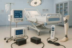
- Medical devices — margin is driven not only by thermal stress but also by uptime requirements, leakage current and isolation constraints, and the safety standards governing patient-contact power design. A supply near its thermal ceiling has less room to maintain those parameters.
- Long-life systems (5, 10+ years) — component aging erodes margin over time, so build in extra from day one.
- Safety-critical or hard-to-service equipment — where a field failure is expensive or dangerous, the extra margin is cheap insurance.
For medical and other regulated designs, this is where derating connects to the broader selection problem. Getting output margin right is one input; matching isolation, leakage, and compliance requirements is another. The complete selection guide for AC-DC medical power supplies covers how these constraints interact.
Common Power Derating Mistakes
Most derating failures trace back to the same short list. Watch for these in your own designs and in any inherited spec you’re asked to validate.
- Sizing to nameplate power without reading the curve at your worst-case operating point.
- Designing for nominal room temperature instead of the highest ambient the system will ever see.
- Ignoring enclosure hot spots and heat recirculation.
- Applying a forced-air rating to a convection application.
- Checking steady-state load only and neglecting startup inrush and transients.
- Leaving no headroom and assuming the rated output is fully available under all conditions.
Any one of these is enough to build a supply that passes on the bench and fails in service.
Power Supply Selection Checklist
Run every item before you commit. One unchecked box can undo the rest.
- Load requirement defined: voltage, current, and total power under full load, including peaks
- Worst-case ambient temperature confirmed, not assumed
- Cooling method verified: forced air, convection, or liquid
- Minimum input voltage identified and used as the design basis
- Altitude and enclosure effects reviewed and applied
- Correct derating curve read at the worst-case operating point
- Headroom applied — 20% baseline, more for demanding conditions
- Startup surges, transients, and fault conditions validated
Quick decision guide:
- Mild ambient, adequate airflow? Air-cooled is the simplest, most cost-effective choice.
- Hot ambient or a strict output guarantee at high temperature? Liquid cooling relies on a controllable coolant temperature rather than on unpredictable ambient air, providing more headroom.
- Single unit falls short after derating? Parallel multiple units, then re-verify the combined derated output clears your load plus headroom.
If you’re still fixing the fundamentals of topology and specification before you get to derating, the switching power supply working principle and selection guide is a useful reference for the layer beneath this one.
Frequently Asked Questions
What is power supply derating?
Power supply derating is the deliberate reduction of a supply’s output below its rated maximum so it operates reliably under real-world conditions. When heat, altitude, or low input voltage cut into available output, derating defines how much you can safely draw. You trade a small amount of peak output for a large gain in reliability and service life.
How much derating should I allow?
Start with about 20% headroom under standard datasheet conditions. Reduce it only when all operating conditions are known, verified, and tightly controlled throughout the product’s lifetime. Increase it for variable environments, enclosed chassis, surge-heavy loads, medical and safety-critical devices, and designs expected to run reliably for many years.
How does temperature affect power supply output?
Rising ambient temperature drives up internal junction temperatures. To keep those junctions within limits, the supply reduces its output. The thermal derating curve captures this relationship. Past the knee of the curve, available output drops steadily as temperature rises. Always read the curve at your worst-case ambient, not the average or nominal value.
Does altitude reduce available output power?
Yes. Higher altitude means lower pressure, thinner air, and reduced heat-carrying capacity. At about 5 km, pressure falls to roughly 55% of sea-level pressure, reducing cooling effectiveness by around 45%. Fan-cooled supplies offset part of this by running faster, but the compensation is partial. Verify against the altitude spec and test at altitude when the site is unusual.
What is the difference between derating and shutdown?
Derating is a proactive design choice you apply during selection to keep the supply inside its safe operating area under all expected conditions. Shutdown is a reactive protection function the supply triggers automatically when a critical threshold is crossed. Derating is how you avoid ever reaching shutdown — never treat shutdown as a substitute for proper derating.
Can I run a power supply at full rated power continuously?
Only if your real operating environment matches the ideal conditions the datasheet assumes, and you’ve confirmed that worst-case temperature, input voltage, altitude, and cooling all stay within those bounds for the product’s operating life. In practice, that’s rare. Applying headroom is the more defensible engineering choice for any real deployment.
Before You Finalize the Supply
Nameplate ratings tell you what a supply can do under ideal conditions. Derating tells you what it will do under yours.
Pull the datasheet for your candidate supply and pin down four numbers: worst-case ambient temperature, cooling method, minimum input voltage, and installation altitude. Read the available derated output directly off the correct curve at that operating point. If the derated number clears your peak load plus headroom, the design is sound. If it doesn’t, size up or parallel units until it does — before you build, not after.
The supply that passes on your bench at 25 °C is not the one that has to survive in the field. Size for the field.