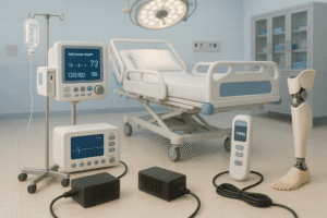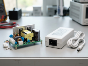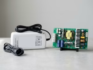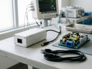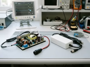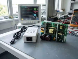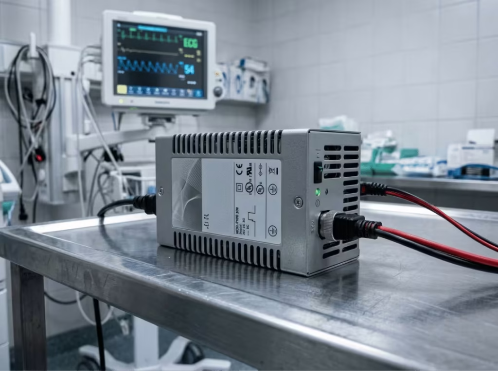
Medical electrical equipment fails IEC 60601-1 certification for many reasons, but one of the most avoidable is this: the protection class was never matched correctly to the actual use case. A power supply that looked right on the spec sheet—correct voltage, acceptable EMC, low cost—turns out to be the wrong architecture for a patient-connected device. The fix requires a redesign late in the program.
Understanding when MOOP (Means of Operator Protection) applies and when MOPP (Means of Patient Protection) is required is not a terminology exercise. It determines the isolation voltage, the insulation structure, the leakage current budget, and the clearance and creepage distances you design in from the start. Change the class, and you change almost everything else.
This article walks through the decision the way a medical power engineer would: from definitions to design impact, from classification logic to real device scenarios. The goal is to give you enough clarity to make the right call early, before it costs you a certification cycle.
What MOP Means in IEC 60601-1—and Why It Splits in Two
MOP stands for Means of Protection—any design element that reduces the risk of electric shock in medical equipment. IEC 60601-1 (3rd edition) introduced a distinction that didn’t exist under earlier standards: protection requirements now depend on who the device contacts, not just what the device does.
That shift gave rise to two separate classifications:
- MOOP — Means of Operator Protection, covering nurses, doctors, technicians, and other trained users who handle the equipment
- MOPP — Means of Patient Protection, covering patients who may be physically connected to the device, sedated, or otherwise unable to react to a fault
A single MOP can be realized through insulation, a protective earth connection, defined clearance (the shortest air path between conductors), or creepage (the shortest surface path). A barrier must independently meet the applicable limits to count as one means of protection.
Every medical device requires at least one MOP. Whether that MOP must be MOOP-grade or MOPP-grade—and whether you need one or two of them—is the decision that defines your power supply specification.
MOOP vs MOPP: The Real Engineering Difference
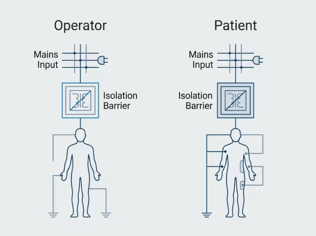
The intuitive summary—MOPP protects patients, MOOP protects operators, MOPP is stricter—is accurate but incomplete. What matters in practice is where the gap between them shows up in hardware.
Parameter | MOOP | MOPP |
|---|---|---|
Protection target | Operator (trained, healthy, can release contact) | Patient (may be connected, sedated, unable to react) |
Standard basis | IEC 60601-1, aligned with IEC 60950/62368 principles | IEC 60601-1, dedicated patient-safety limits |
Typical isolation test voltage | Up to 3,000 Vac (2× MOOP) | Up to 4,000 Vac (2× MOPP) |
Creepage (2× level) | ~5 mm | ~8 mm |
Clearance (2× level) | ~4 mm | ~5 mm |
Patient leakage current | Higher limits permitted | Much lower—often in the microamp range |
Typical applications | IVD lab equipment, operator-only devices | Patient monitors, infusion pumps, imaging, defibrillators |
The column that catches most teams off guard is the isolation voltage. A supply certified to 2× MOOP holds 3,000 Vac across the primary-to-secondary barrier. That same supply cannot satisfy 2× MOPP, which requires 4,000 Vac. The insulation, the physical layout, and the transformer construction all have to be designed for that higher figure. No amount of paperwork bridges the gap—it lives in the hardware.
MOPP is not a tighter version of MOOP. It is a different safety class with different limits, designed around the assumption that the patient cannot protect themselves.
1× MOOP, 2× MOOP, 1× MOPP, 2× MOPP: What the Numbers Actually Mean
The number in front indicates how many independent layers of protection separate hazardous voltage from the protected person.
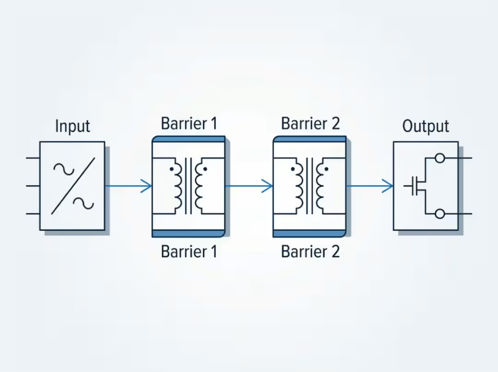
One means of protection (1×): A single barrier separates the dangerous potential from the person. If that barrier holds, the person is safe. If it fails, there is no backup. This level is acceptable in low-risk configurations where the risk analysis supports it.
Two means of protection (2×): Two independent barriers are present. A single fault—one insulation failure, one component breakdown—cannot remove both. The second barrier continues to protect. This is why 2× MOPP is the de facto requirement for most patient-connected medical devices: a single fault condition is considered credible, and safety must withstand it.
How each combination plays out in practice:
- 1× MOOP — Minimum operator protection. Acceptable for equipment handled only by trained staff, where the patient is never present.
- 2× MOOP — Double operator protection. Applied where operator exposure is frequent or environmental conditions are more demanding, such as a high-humidity laboratory.
- 1× MOPP — Single patient-grade protection. Higher isolation and lower leakage than any MOOP layer, but without the redundancy of 2× MOPP.
- 2× MOPP — Two independent patient-grade barriers. Required for most devices that contact, connect to, or are used in close proximity to a patient. To qualify, a power supply must withstand isolation testing at 4 kV AC, maintain 8 mm creepage and 5 mm clearance at the primary-to-secondary boundary, and hold patient leakage to the applicable limit under both normal and single-fault conditions. All criteria apply simultaneously—meeting four of five is not sufficient.
For deeper background on how 2× MOPP isolation is implemented at the power supply level, see What Is 2×MOPP in Medical Power Supplies?
When Does a Device Require MOPP Instead of MOOP?
The controlling question is physical contact with the patient—direct or conductive. If the device or its output can reach the patient under normal use or under a single-fault condition, MOPP applies.
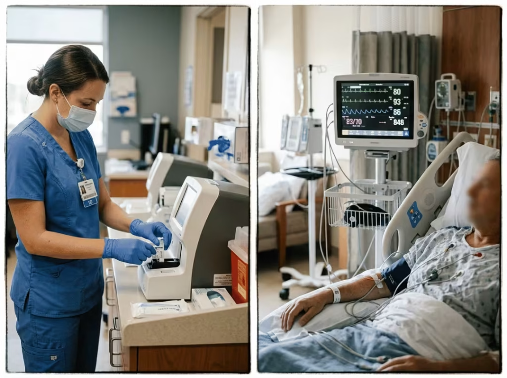
Applied part classification drives this decision. IEC 60601-1 defines three applied-part types, and the type determines the leakage limit your power supply must hold:
- Type B — Body contact, typically non-conductive, can be removed quickly. Hospital beds, operating tables, some monitors.
- Type BF — Body floating, isolated from earth, medium or longer-term contact. Ultrasound probes, blood pressure cuffs, ECG electrodes.
- Type CF — Cardiac floating, for parts that may contact the heart directly. Pacemakers, defibrillators, cardiac catheters.
Patient leakage limits tighten sharply as classification rises: BF devices must hold patient leakage below 100 µA under normal conditions; CF devices must hold it below 10 µA—an order of magnitude lower. A power supply architecture that clears BF requirements can fail CF validation outright.
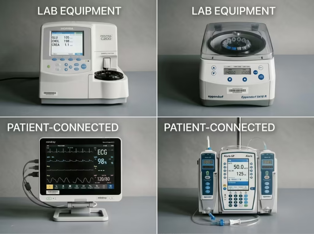
Devices that typically require MOOP only:
In vitro diagnostic (IVD) equipment operates in laboratories where patients are not normally present. The operator loads samples, runs tests, and interprets results. Patient contact is not part of the workflow.
- Blood chemistry analyzers
- Centrifuges and sterilizers
- Benchtop diagnostic instruments
- Automated slide stainers
Devices that require MOPP—usually 2× MOPP:
Any device whose applied parts contact the patient, carry electrical signals from the patient, or are positioned close enough that a fault could deliver current to the patient.
- Bedside patient monitors and ECG systems
- Infusion pumps and ventilators
- Ultrasound scanners and imaging equipment
- Defibrillators and cardiac monitors
- Hospital beds and patient-area lighting within the patient environment
A point engineers frequently miss: IEC 60601-1 treats proximity as potential contact in certain configurations. A device that never directly touches the patient may still require MOPP if it operates within the patient environment and a conductive fault path to the patient exists. When the risk analysis is ambiguous, MOPP is the defensible choice.
How MOOP vs MOPP Changes Power Supply Design
Selecting a protection class is not a compliance formality. It propagates through four interdependent design parameters. Each one must be resolved before the supply architecture is final.
Insulation and Isolation
MOPP demands a higher isolation barrier than MOOP at every insulation level. At 2× MOPP, the transformer must withstand 4,000 Vac across the primary-to-secondary boundary—not as a peak transient, but as a sustained test. The winding construction, insulation tape, and creepage across the bobbin must all support this.
A 2× MOOP supply tested to 3,000 Vac cannot satisfy this requirement without a redesign of the isolation transformer. This is the most common cause of certification failure when an industrial or commercial supply is used in a patient-contact application.
Leakage Current and the EMC Tradeoff
Patient leakage current is the parameter that most directly constrains power supply design for MOPP applications. The EMI filter that suppresses conducted emissions is also the primary source of leakage current: Y-capacitors from line or neutral to earth carry common-mode noise away, but they also provide a path for leakage to flow toward the patient connection.
Increasing Y-capacitor values improves EMC performance and typically increases leakage. Reducing them to meet a leakage limit can push emissions over the allowed threshold. This trade-off cannot be resolved by optimizing one side in isolation—it requires system-level filter design that balances both constraints.
For CF-classified devices, where patient leakage must remain below 10 µA, the Y-capacitor values may need to be very small or eliminated entirely at certain positions. The EMC case must then be closed through other means: shielding, common-mode chokes, differential-mode filtering, or careful PCB layout. This is one reason why a medical-grade supply is an engineered product, not a general-purpose supply with a different certification label.
For a detailed look at how leakage current limits interact with IEC 60601-1 compliance requirements, see What Is a Medical Grade Power Supply?
Creepage and Clearance
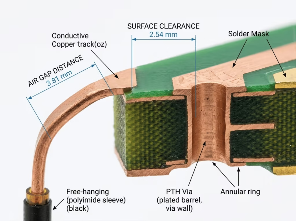
Creepage and clearance requirements expand significantly from MOOP to MOPP, and from 1× to 2× protection levels. At 2× MOPP, primary-to-secondary creepage is typically 8 mm, and clearance is 5 mm. These distances are not met by applying conformal coating—they must exist in the physical geometry of the board layout, the transformer bobbin, and the enclosure.
In compact power supply designs, this is a real constraint. A package that maintains the required spacing at 2× MOOP may not have sufficient physical space to meet 2× MOPP without a redesign of the PCB or transformer form factor. Discovering this late—after layout is frozen—is expensive.
Dielectric Strength
Higher isolation test voltages at MOPP levels mean that every component in the isolation barrier—transformer winding insulation, PCB substrate, slot apertures, creepage barriers—must survive the hipot test without breakdown. Materials that are acceptable at 2× MOOP levels may exhibit partial discharge or fail outright at 4,000 Vac. Transformer tape, primary-to-secondary slot insulation, and bobbin construction all require verification against the higher voltage.
Specifying a 2× MOPP supply early in a program often eliminates the need for an external isolation transformer later. That transformer adds board area, weight, cost, and another certification variable. A single, well-specified internal supply that carries the full 2× MOPP rating is usually the cleaner architecture.
Protection Class by Device Type: Practical Examples
The following scenarios reflect common real-world configurations. They are not a substitute for a device-specific risk analysis, but they illustrate how the decision logic works in practice.
Ultrasound scanner (diagnostic imaging)
The transducer contacts the patient’s skin for extended periods. Energy is delivered directly to the patient’s surface. Applied part type: BF or CF depending on configuration. Requirement: 2× MOPP, with low leakage to maintain signal integrity and patient safety during continuous contact.
Bedside patient monitor (ICU or ward)
Electrodes measure ECG, SpO2, and other parameters through prolonged skin contact. Applied part type: BF. Requirement: 2× MOPP. The combination of continuous connection and patient vulnerability mandates the full redundancy of double patient-grade protection.
Infusion pump
Delivers fluid into the patient’s bloodstream through an IV line. Although the pump mechanism is not electrically connected to the patient, the fluid path establishes a conductive link. Requirement: 2× MOPP, with careful leakage analysis of the fluid-path coupling.
Blood chemistry analyzer (clinical laboratory)
Operated exclusively by laboratory technicians; patients are not present during operation. No applied parts contact any person during testing. Applied part type: none at the power supply interface. Requirement: MOOP-level protection is generally sufficient. Verify that no accessory or consumable creates a patient conductive path before finalizing this classification.
Defibrillator
Delivers a controlled high-energy shock directly to the patient’s chest or internally via paddles or pads. Applied part type: CF (defibrillation-proof). Requirement: 2× MOPP, with the strictest leakage limits and full fault-tolerance in the protection architecture.
Common Misclassifications and Design Errors
Using a 2× MOOP supply for a patient-contact device. The isolation voltage and leakage limits do not meet MOPP requirements. The supply will fail hipot and leakage testing under IEC 60601-1 for a patient-connected application, regardless of what the datasheet says about “medical grade.”
Assuming IVD equipment never needs MOPP. It typically doesn’t—but if a fluid path, accessory, or system integration creates a conductive route to a patient, the classification changes. Evaluate each configuration, not just the instrument category.
Treating proximity as automatically safe. The standard’s risk logic accounts for the possibility that a patient could contact a device in the patient environment, even without direct connection. Devices within the patient zone require a more careful analysis than devices in a separate room.
Treating the 2× layers as two tests, not two barriers. Two means of protection means two physically independent barriers. A single reinforced barrier tested twice does not satisfy 2× MOPP. Each barrier must independently survive the applicable test and provide protection if the other fails.
Relying on an industrial double-insulated supply. Industrial double insulation is defined by IEC 62368-1 and carries different isolation, spacing, and leakage limits than medical 2× MOPP. The two ratings are not interchangeable. A supply designed and certified for IEC 62368-1 will not pass an IEC 60601-1 patient-protection evaluation without a hardware redesign.
Frequently Asked Questions
Is MOPP always more stringent than MOOP?
Yes. At every insulation level, MOPP requires higher isolation voltage, larger creepage and clearance distances, and lower patient leakage current than the corresponding MOOP rating. The difference exists because patients cannot protect themselves from a fault the way a trained operator can.
Do all medical devices require 2× MOPP?
No. The requirement depends on the applied-part classification and the risk analysis. Devices with no patient contact typically require only MOOP-level protection. Patient-connected devices generally require 2× MOPP. Verify against the specific use case rather than applying a blanket rule.
Can a MOOP-rated power supply be used in a patient-connected device?
No. A MOOP barrier is not built to meet patient leakage limits or the isolation requirements demanded by patient protection. Installing a MOOP-rated supply in a patient-connected device will result in certification failures during leakage current and hipot testing.
What is the practical difference between 2× MOOP and 2× MOPP?
Both have two independent protection barriers. The difference is the performance each barrier must achieve: 2× MOPP requires up to 4,000 Vac isolation, 8 mm creepage, 5 mm clearance, and patient leakage well below the limits that 2× MOOP must satisfy. A supply that passes 2× MOOP testing will not automatically pass 2× MOPP.
What does “2 MOPP” mean on a medical power supply datasheet?
It means the supply has been designed and tested to provide two independent means of patient protection. The insulation, transformer construction, PCB spacing, and leakage current all comply with the 2× MOPP requirements in IEC 60601-1. When evaluating a supply for patient-contact applications, confirm the specific isolation voltage, leakage current figures, and creepage/clearance dimensions on the datasheet rather than relying on the label alone.
Does a medical power supply always need IEC 60601-1 certification?
For any supply that powers medical electrical equipment, IEC 60601-1 (or equivalent national adoption) is the baseline certification required for market access in most regions. The specific protection level—MOOP or MOPP, 1× or 2×—must match the device’s applied-part classification and risk analysis.
Choosing the Right Protection Level: A Decision Path
Rather than working through the entire IEC 60601-1 framework from scratch, the following sequence covers the decisions that eliminate the most risk:
- Define the patient contact scenario. Does the device, its applied parts, or any conductive path from the device reach a patient during normal use or under a credible fault?
- Determine the applied-part classification. Type B, BF, or CF, based on the nature of contact. This sets the patient leakage current limit.
- Establish the required protection class. Patient contact generally means MOPP; no patient contact may permit MOOP. Within MOPP, most patient-connected applications require 2× MOPP to survive a single fault.
- Verify the power supply against the isolation and leakage specifications. Confirm isolation voltage, creepage, clearance, and patient leakage current for the declared protection level—not just the certification label.
- Evaluate the EMC and leakage tradeoff. Confirm that the filter architecture balances emissions compliance with the leakage limit your applied-part class requires. For CF applications, this tradeoff needs explicit attention.
- Lock the decision before layout. Changing the protection class after PCB layout is frozen almost always forces a hardware revision. The spacing, transformer, and filter design all depend on this decision being made first.
For guidance on the full selection process across supply formats and device categories, see The Critical Role of MOOP and MOPP in Medical Power Adapters.
Summary
MOOP and MOPP are not interchangeable labels for different levels of the same thing. They are distinct safety classifications that apply to different users, impose different hardware requirements, and lead to fundamentally different power supply architectures.
The classification decision—which class, how many layers—should be made before the power supply is selected, before the PCB is laid out, and before the isolation transformer is specified. Made early, it simplifies everything downstream. Made late, it can force a full redesign mid-certification program.
If you are developing a device with patient contact and need to confirm the right protection architecture for your power supply, contact the engineering team at Quankang to discuss your applied-part classification, leakage targets, and isolation requirements.