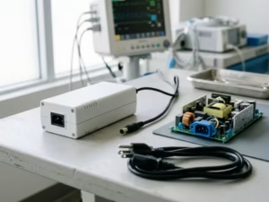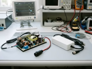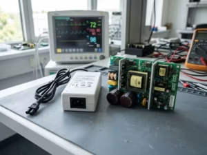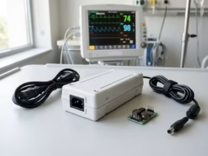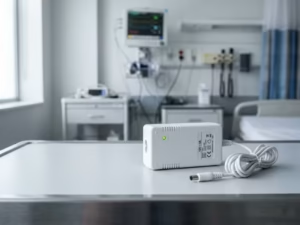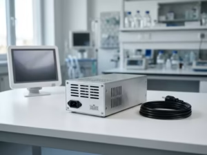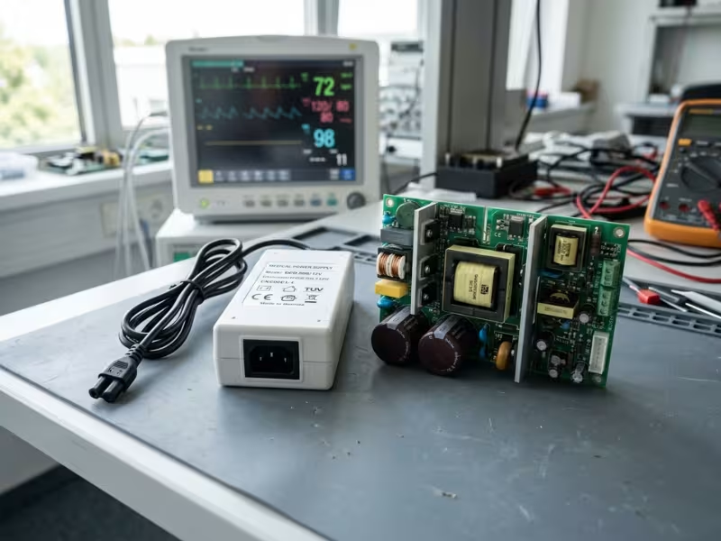
Medical device teams often focus on features first. But in many projects, the power supply exposes compliance problems before any other part of the system.
Three issues drive most of that pressure: safety, isolation, and EMC. They rarely act alone. A change in one usually shifts the other two.
The IEC 60601 framework sets the rules for all three. This guide does not walk through every clause. Instead, it focuses on the design decisions that usually decide success or failure: where leakage current rises, where isolation breaks down, and where EMC problems start long before lab testing.
Why Power Supply Design Often Determines Compliance Outcomes
When a medical device fails its first safety or EMC test, I check the power stage first. In most projects, that is where the trouble starts.
The power supply touches everything. It sets the grounding scheme, feeds every rail, and holds the main barrier between mains and the patient. A choice made there shows up in the sensor front end, the cable harness, and the enclosure.
That is why the three biggest problems tend to gather there:
- Leakage: Y-capacitors that quiet switching noise also open a path for current to reach people.
- Isolation: The transformer and the PCB around it decide whether you keep your creepage distance or lose it to a crowded layout.
- EMC: A fast-switching converter is often the loudest noise source in the device, and cables carry that noise out like antennas.
Fix one, and you often push another. Shrink the Y-caps to cut leakage, and conducted emissions climb.
Late fixes cost the most. Before layout freeze, a filter change may take an afternoon. After it, teams commonly face a new board spin, fresh safety tests, and repeat lab fees.
Devices keep getting more connected, but the rules stay the same. Wi-Fi, Bluetooth, USB ports, and docking stations each open new paths for leakage and noise. A USB cable to a non-medical laptop can even bridge your isolation barrier. Touch current and patient leakage limits still apply to every port and every cable.
Lock the Design Inputs Before You Design the Power Architecture
Most power redesigns don’t start with a bad circuit. They start with a missing input. A team assumes hospital use, and then a home version appears on the roadmap. Or a team picks Type BF, and then a cardiac lead joins the product plan.
Before anyone sketches a topology, teams should answer four questions and write the answers down.
Pin Down the Standards That Shape Your Design
IEC 60601-1 sets your safety baseline. IEC 60601-1-2 sets your EMC test levels. Almost every device needs both.
Then add the collateral standards that match your use case. IEC 60601-1-11 raises the demands for home healthcare, and IEC 60601-1-12 covers emergency transport. Particular standards in the -2-xx series can also override general limits for devices like infusion pumps.
List every target market early. The US uses ANSI/AAMI ES60601-1, while most other markets follow IEC or EN versions through the CB scheme. A market added late can bring a new input range or test level.
Classify the Device and Its Applied Parts
A Class I device relies on protective earth. That gives you more room for Y-capacitance, but you take on earth leakage limits. A Class II device has no earth, so double or reinforced insulation carries the full load. That is why most home adapters go Class II.
Applied part type sets your patient leakage budget:
- Type B and BF: Typically 100 µA in normal conditions
- Type CF: Typically 10 µA in normal conditions and 50 µA under a single fault
Moving from BF to CF late can force an isolated DC-DC stage, smaller Y-caps, and a new filter.
Define Where and How the Device Runs
An ICU, a living room, and an ambulance each bring different power quality and noise. Name your main setting and your worst one.
Then define the duty cycle and the enclosure. A sealed, fanless case can commonly run 15–20 °C hotter inside. That single number drives derating, capacitor life, and your efficiency target.
Treat Risk Management as a Design Input
ISO 14971 belongs in the design, not only the technical file. If a failed regulator could overheat a part near the patient, add independent overvoltage protection. If power loss would stop therapy, plan battery backup and an alarm. Turn each hazard into a requirement now.
Decide Early Whether Off-the-Shelf Is Enough
This choice shapes your schedule more than almost any circuit detail. Teams should make it before anyone draws the first schematic.
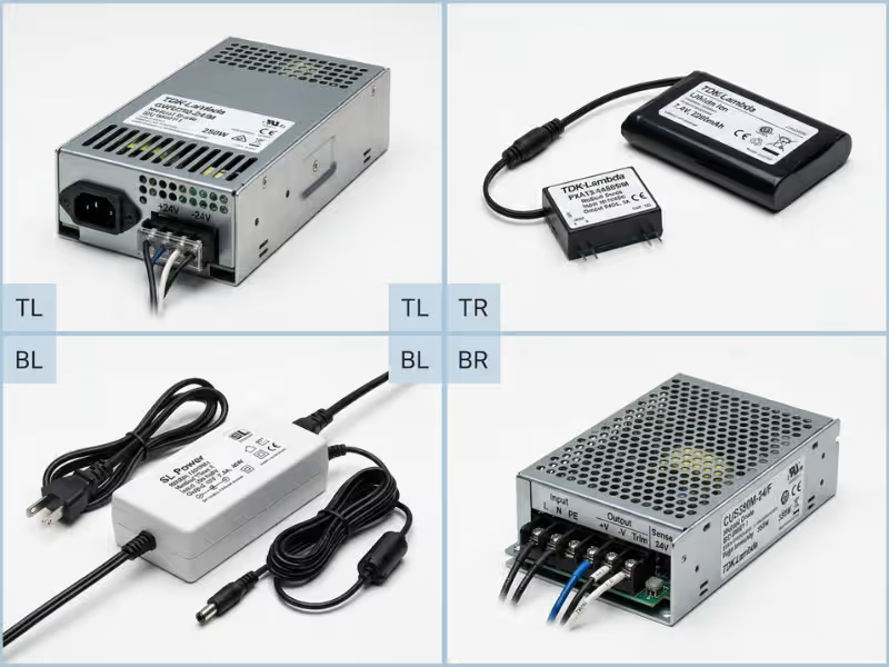
When off-the-shelf earns its place. A pre-certified medical supply arrives with a CB report, 2x MOPP isolation, and known leakage figures. Teams comparing real options can review medical power supplies to see how these specifications typically appear at the product level. For standard rails and moderate power, this route can save months of safety work.
What it can’t do for you. A certified supply doesn’t certify your device. You still own system leakage, which adds up across every Y-cap, cable, and applied part. You also own EMC, because your layout and cables decide the final result. A CB report is a head start, not a finish line.
When custom makes more sense. Common triggers include odd rail combinations, tight space, CF-level leakage targets, and high volumes where unit cost matters. Many teams land in the middle with a modified standard unit.
Option | Best For | Main Advantage | Main Constraint |
|---|---|---|---|
Off-the-shelf medical | Standard rails, low to mid volume | Pre-certified, fast to market | Fixed outputs and size |
Modified standard | Near-fit needs, small changes | Reuses most test evidence | Changes may trigger partial retest |
Fully custom | High volume, tight space, CF targets | Exact fit for your device | Longer schedule, higher NRE |
Safety Design Essentials
Safety problems rarely appear out of nowhere in the test lab. The circuit usually built them in months earlier. Four areas decide whether your supply passes on the first try.
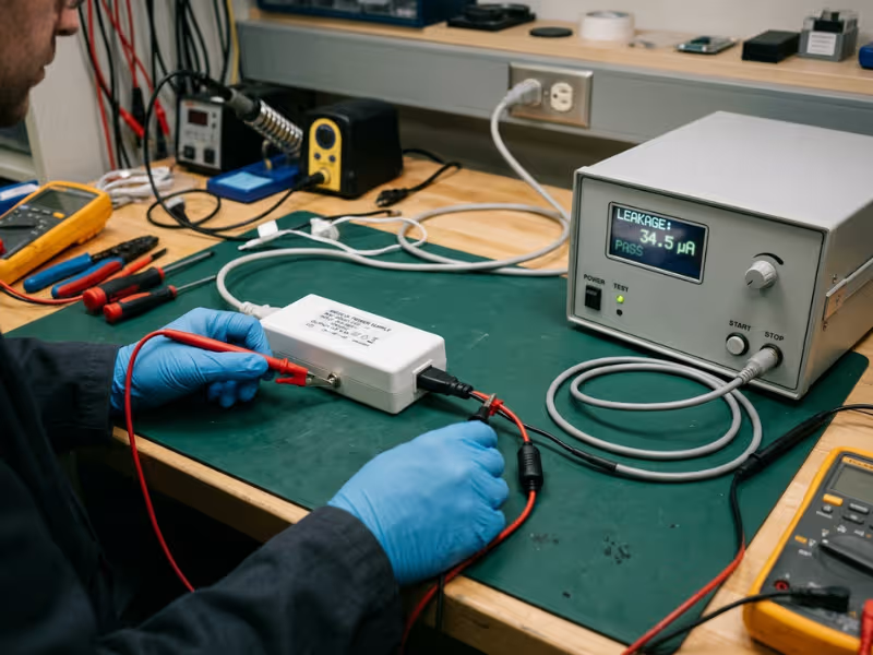
Leakage Current Is a Design Problem, Not a Test-Room Surprise
IEC 60601-1 tracks three leakage paths:
- Earth leakage flows through the protective earth conductor in Class I devices.
- Touch current flows from the enclosure through a person. The limit is typically 100 µA normal and 500 µA under a single fault.
- Patient leakage flows through the applied part, with limits set by the B, BF, or CF rating.
Y-capacitors cause most leakage. At 264 VAC and 60 Hz, each 1 nF of Y-cap passes roughly 100 µA. So a 1 nF part that looks harmless can use up an entire touch-current budget on its own.
Transformer interwinding capacitance, heatsinks near secondary copper, and long traces near the barrier add more. A practical approach is to set a leakage budget early and keep 30–50% margin for production spread.
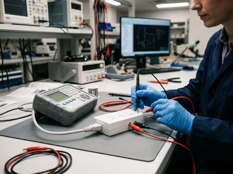
Expect tension. Higher switching frequency shrinks magnetics but raises noise. Tighter transformer coupling improves efficiency but adds capacitance. Both push you toward more Y-cap.
Creepage and Clearance Must Survive the Real Environment
Clearance is the shortest path through air and protects against flashover. Creepage is the shortest path along a surface and protects against tracking from dust and moisture.
Working voltage, pollution degree, and the PCB’s tracking index set your distances. Most medical designs assume pollution degree 2. Above 2,000 m altitude, clearances commonly need a correction factor.
On the board, these habits protect your margin:
- Mill slots under optocouplers and transformers. Slots narrower than about 1 mm usually don’t count.
- Keep screws, standoffs, and heatsinks out of the barrier zone.
- Count on conformal coating only when the process meets the standard’s qualification rules.
Measure creepage on the physical board too. Solder fillets and component tilt can quietly steal a millimeter.
Safety-Critical Component Choices Affect Single-Fault Behavior
- Y-capacitors: Use Y1-rated parts across reinforced insulation.
- Transformers: Choose a certified insulation system rated above your worst-case hot spot.
- Isolators: Confirm approvals at the insulation level you need.
- Fuses: Many designs fuse each supply line.
- OCP and OVP: Keep them independent of the main control loop.
Derate everything. Electrolytic capacitor life roughly halves with every 10 °C rise. Plan for aging as well, since optocouplers lose current transfer ratio over the years.
Risk Analysis Should Shape the Circuit, Not Just the Documentation
A strong FMEA changes the schematic. Short and open each critical part, then follow the chain to the patient. A failed feedback optocoupler can drive the output high, overheat a regulator beside a skin sensor, and cause a burn.
Once you see the chain, the fix becomes clear: add OVP with its own sensing path. Each fault found before layout costs a resistor. The same fault found late costs a board spin.
Isolation Design Essentials
An isolation barrier looks simple on a schematic: one dashed line. On real hardware, that line must block mains voltage for years, pass power and data, and keep noise from crossing.
Isolation Is Both a Patient-Safety Barrier and a System Boundary
The standard recognizes three levels:
- Functional isolation lets the circuit work but earns no safety credit.
- Basic isolation gives one level of protection, roughly 1x MOPP.
- Reinforced isolation equals double insulation, roughly 2x MOPP.
Teams often mislabel a functional barrier as basic because it “looks isolated.” The test lab will check.
Every barrier also sets a noise boundary. A transformer may commonly add 20–50 pF across the barrier, while a digital isolator may add only 1–2 pF. On an ECG front end, that difference can show up directly on the trace.
Understand the Ratings Behind the Barrier
A “5 kV isolation” claim tells you little on its own. Check three numbers:
- Working voltage: The real peak across the barrier, including switching spikes
- Test voltage: Typically 4,000 VAC for 2x MOPP and 1,500 VAC for 1x MOPP at common mains voltages
- Transient withstand: Often 2,500 V peak or more for 230 V supplies
A passed hipot shows the barrier held at that moment. It does not prove long-term insulation life. For high-stress designs, such as defibrillator-proof parts, ask for partial discharge data.
Choose the Isolation Technology Around Application Risk
Transformers move real power and carry the main barrier. Ask for a split bobbin or shield winding when leakage is tight. Optocouplers offer wide packages but drift with age, especially when hot. Digital isolators are fast and stable, but confirm a reinforced rating under IEC 60747-17 and a package wide enough for your creepage target.
My quick rule: a transformer for power, a digital isolator for fast signals, and an optocoupler where simplicity matters more than lifetime drift.
A Good Barrier Can Still Fail in Layout
- Keep the barrier continuous on every layer, including inner layers.
- Control return paths by placing Y-capacitors right next to the transformer.
- Watch board edges and hardware. A screw near the barrier can cut an 8 mm gap in half.
- Treat the ferrite core as conductive and assign it to one side.
Before release, I mark the barrier in red on every layer and walk it by eye. It catches problems that design rule checks miss.
EMC Design Essentials
A power supply can pass every safety test and still fail EMC on its first lab visit. EMC problems are hard to see on a schematic and rarely have a single cause.
What IEC 60601-1-2 Changes for Power Design
The standard tests emissions and immunity. The 4th edition commonly calls for ±8 kV contact and ±15 kV air ESD. Home healthcare devices face 10 V/m radiated immunity, and a proximity test adds 9–28 V/m fields from nearby radios.
The bigger shift is essential performance. The device must keep doing its clinical job during the disturbance. A pump that misdoses during a burst is a safety failure, not just a test failure. Define pass criteria in measurable terms, such as “flow rate stays within ±5%.”
Conducted Emissions Start With Switching Noise and Return Paths
Conducted emissions cover 150 kHz to 30 MHz. Differential-mode noise usually dominates below 1–2 MHz and responds to X-capacitors. Common-mode noise usually dominates higher up and responds to chokes and Y-capacitors.
Use a CM/DM splitter before adding parts. In medical designs, a practical approach is to reach for more choke inductance, a transformer shield winding, slower edges, and tighter loops before adding Y-capacitance. Recheck leakage every time you do.
Radiated Emissions Are Often Layout Problems in Disguise
From 30 MHz to 1 GHz, copper and cables act like antennas. Teams should:
- Shrink the hot loop formed by the input capacitor, switch, and transformer primary.
- Keep switch-node copper small and tie heatsinks to a quiet reference.
- Bond chassis to circuit ground at one point, near the cable entry.
- Treat cables as the real antenna. A clamp-on ferrite confirms it, and a board fix makes it permanent.
Immunity Is Where “It Powers On” Is Not Enough
ESD, EFT/burst, surge, RF immunity, and voltage dips each stress a different weak point. A monitor that reboots during a half-cycle dropout fails, even if it recovers. Test while the device runs its clinical task, and log outputs during every disturbance.
Pre-Compliance Testing Is Where Redesigns Can Still Be Avoided
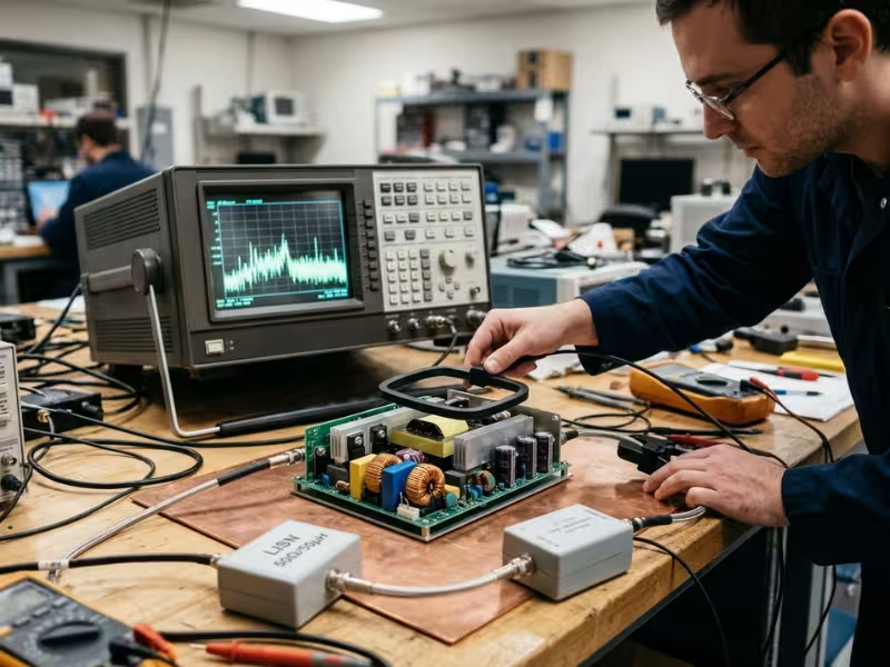
A spectrum analyzer with a LISN, near-field probes, and a current clamp go a long way. Sharp peaks at switching harmonics point to the converter. A broad hump between 30 and 100 MHz usually means common-mode current on a cable. Aim for at least 6 dB of bench margin.
Bring in an EMC consultant when two design changes don’t move the result. A day of expert time costs far less than a third board spin.
Design Priorities Change by Device Scenario
The core rules stay the same, but each scenario changes which rules need the most margin.
Bedside and Continuously Powered Devices
Reliability comes first. Size for full load at the hottest internal temperature. Leakage needs extra margin, since one patient may connect to several devices at once. Many designs target 10–20 ms of hold-up time, plus a common-mode choke at the DC output to protect ECG leads.
Portable and Battery-Assisted Devices
Heat and size drive most decisions, and surface temperature limits make efficiency a safety issue. Test leakage while the device charges and operates at once. Also watch beat frequencies: an adapter at 65 kHz and a converter at 70 kHz can create a 5 kHz tone in sensitive circuits.
Home Healthcare Devices
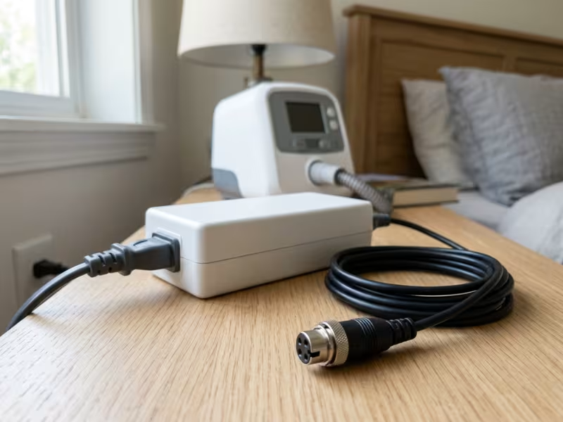
Homes bring Wi-Fi routers, induction cooktops, extension cords, and wet hands. A Class II external adapter with 2x MOPP is often the safest fit, because it keeps mains voltage out of the device enclosure. For devices that need specific connectors, output combinations, or enclosure constraints, custom power adapters can simplify insulation strategy and replacement. Add a keyed DC connector so a laptop charger cannot fit.
High-Immunity or Clinically Sensitive Devices
Ventilators and defibrillators cannot pause. Size surge protection with margin, add brownout detection, and use watchdogs that never drop alarms. Defibrillation-proof parts typically must survive a 5 kV pulse. I often test one level above the required immunity limit to prove real margin.
Common Failure Patterns That Trigger Late Redesigns
These six patterns appear again and again in redesign reviews:
- The leakage budget shows up after the prototype. Start a spreadsheet at the schematic stage and update it with each change.
- Creepage disappears in a dense layout. A clean 8 mm gap quietly becomes 5 mm. Lock keep-outs into CAD rules before routing.
- An industrial isolator ends up in a medical barrier. Check each rating against your insulation diagram, not the headline kV figure.
- The EMC filter changes, but nobody rechecks leakage. Make leakage recalculation a required step in your change log.
- Thermal limits appear after the enclosure closes. Validate with a closed-case prototype.
- The test house becomes the design team. Design for about 6 dB of EMC margin and 30% leakage margin, so the lab confirms your design instead of rewriting it.
Practical Design Checklist
Teams should sign off each step before moving on:
- Classify the device: Class I or II, and the strictest applied part type you might need.
- Lock standards and environment: Standards, markets, use setting, and worst-case internal temperature.
- Define isolation strategy: Draw an insulation diagram before the schematic.
- Set leakage and insulation targets: Add margin to every limit.
- Choose safety-critical components: Match ratings to the insulation diagram and derate.
- Design the layout around barrier and noise paths.
- Run pre-compliance before layout freeze.
- Document your risk-based rationale in the ISO 14971 file.
Design Stage | What Must Be Confirmed | Typical Risk If Missed |
|---|---|---|
Classify the device | Class I or II, applied part type | Late CF move forces new isolation |
Lock standards and environment | Markets, use setting, max ambient | Second test round |
Define isolation strategy | Barrier levels, MOPP/MOOP | Barrier misclassified at lab |
Set targets | Leakage budget, spacing, test voltages | Touch current failure after EMC fixes |
Choose components | Medical ratings, derating | Rejected isolator, early wear-out |
Design layout | Keep-outs, loop area, continuity | Lost creepage, radiated failure |
Run pre-compliance | Bench margin on emissions and leakage | Failed lab visit, board spin |
Document rationale | Risk links for each protection | Audit findings, delayed approval |
FAQs
What is the difference between IEC 60601-1 and IEC 60601-1-2?
IEC 60601-1 covers basic safety, including shock, fire, and heat. IEC 60601-1-2 covers EMC. A supply can carry its own IEC 60601-1 CB report, but EMC results belong to the finished device.
Can I use a standard industrial power supply in a medical device?
Sometimes, but industrial supplies typically have higher leakage and operator-level insulation. Closing the gap means added isolation and full system testing. For devices with applied parts, a certified medical supply usually costs less overall.
What is the difference between basic, functional, and reinforced isolation?
Functional isolation earns no safety credit. Basic gives one level of protection, roughly 1x MOPP. Reinforced gives two levels in one barrier, roughly 2x MOPP.
How does isolation affect EMC performance?
Barrier capacitance gives common-mode noise a path to the patient side. Lower capacitance usually means a quieter patient cable and less leakage.
How do I choose between an off-the-shelf and custom medical power supply?
Start with off-the-shelf. If a standard unit needs more than two workarounds to fit, a modified or custom design often costs less overall.
Conclusion
Safety, isolation, and EMC never move alone. Add a Y-capacitor to pass emissions, and touch current climbs. Treat all three as one decision, and you avoid most late surprises.
IEC 60601-1 and IEC 60601-1-2 set the floor for test day. Design margin decides how devices behave across thousands of units, aging parts, and messy real-world wiring. A practical target is 30% leakage headroom and 6 dB of EMC margin.
Your next step: Walk your current power architecture through the checklist above, and run pre-compliance on your bench before layout freeze. If you are comparing different end-use settings, these application examples can help connect power design choices to real device scenarios.