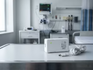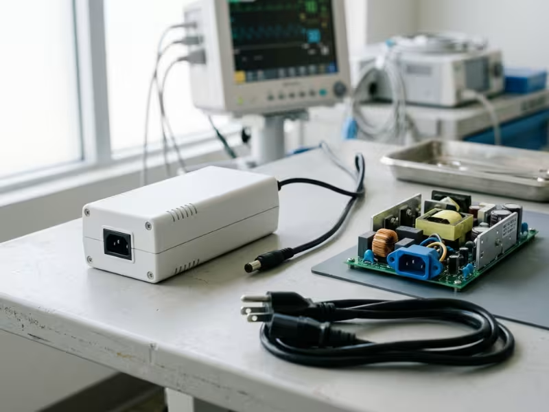
Many medical teams know they need isolation. The harder questions come later. Where should the barrier sit? How low must leakage current stay? And how do you hit both targets at once?
I often see good projects slow down at this point. The cause is rarely one bad part. EMI, leakage, layout, and certification start pulling in different directions, and nobody notices until the test lab does.
In this guide, I show how isolation and leakage work together in real medical power supplies under the IEC 60601 framework. You’ll see where each barrier comes from, where leakage really flows, and how to set both targets before your layout locks.
Why Isolation and Leakage Belong in the Same Conversation
Many teams split this work in two. One engineer picks a 2xMOPP supply. Another runs leakage tests months later. That split causes trouble, because both results come from the same parts, the same layout, and the same barrier.
Here’s how I explain the link when a project first lands on my desk.
Isolation Builds the Wall
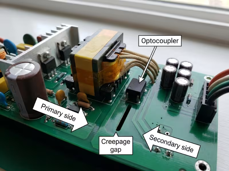
Isolation keeps mains voltage away from the patient. It comes from insulation, creepage, and clearance between the primary and secondary sides. Most medical supplies use two means of patient protection (2xMOPP). As a common design reference, that means a 4,000 VAC test and about 8 mm of creepage at 250 VAC working voltage.
Think of it as a wall. It stops a direct shock, even if one layer of protection fails.
Leakage Shows What Still Gets Through
No wall is perfect. AC current still crosses the barrier through stray capacitance, filter parts, and cables. Leakage current measures that flow.
The limits are tight. Typical normal-condition patient leakage limits are 100 µA for Type BF and only 10 µA for Type CF. Isolation tells you the wall exists. Leakage tells you how much current slips past it on a real device, with real cables, on real mains.
Why Fixing One Can Break the Other
Every fix for one goal pushes on the other. A stronger EMI filter lowers emissions but raises leakage. A transformer built for wider spacing cuts capacitance but grows in size and adds ringing. A tighter layout saves space but can shrink creepage.
That’s why I treat isolation and leakage as one design decision. Set the barrier and the leakage budget together, before anyone freezes the filter or the board.
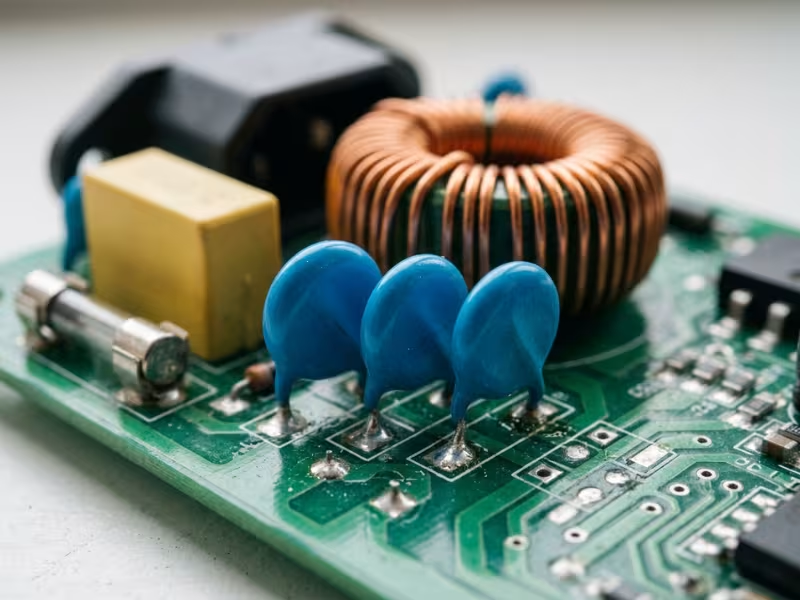
The IEC 60601 Requirements That Matter Most
You don’t need to read the whole IEC 60601 family to choose a supply. You need to know which clauses set your isolation target and leakage limits, and which ones can quietly move them.
I sort the requirements into three layers. The general standard sets the rules. Add-on standards adjust them. Certificates show how well a part meets them, but only within their scope.
IEC 60601-1 Sets the Safety Framework
IEC 60601-1 asks two things of your device. It must deliver basic safety, with no shock, fire, or burn hazards. It must also keep its essential performance, such as a ventilator delivering breaths or a monitor raising an alarm.
The standard ties both to risk management under ISO 14971. Your risk file decides how much margin you need and which faults you must test. A power decision without a matching risk entry will draw questions from your lab.
Two classifications shape the power design most:
- Class I or Class II. Class I relies on protective earth as one means of protection. Class II has no earth and relies on double or reinforced insulation. That choice changes your leakage paths, your inlet, and how you handle filtering.
- Type B, BF, or CF applied parts. These set your patient leakage limits. Map every part that touches the patient. The strictest one sets the target for the whole power tree.
Collateral and Particular Standards Can Move the Target
Once you know the base rules, check which add-on standards apply. They rarely change the physics, but they often change your margins.
- IEC 60601-1-2 covers EMC. Its emissions and immunity levels decide how much filtering you need, and filtering affects leakage.
- IEC 60601-1-11 covers home healthcare. It assumes lay users, rough handling, and outlets that may lack a working ground.
- Particular standards (the “-2-” series) for ECG monitors, infusion pumps, or ventilators may add defibrillation-proof rules or supply interruption tests. They often override the general standard, so check them early.
Certificates Help, but Read the Edition and Scope
A CB report can save you months of testing. It only helps if it matches your use case.
Start with the edition. Most markets now expect Edition 3.1 or 3.2 with amendments. An older report may leave gaps your lab has to close.
Then read the scope. The “conditions of acceptability” list the rated working voltage, ambient temperature, altitude, mounting, and cooling. If your enclosure runs hotter or your mounting differs, part of the certificate stops covering you.
Above all, remember this: a component certificate is not device approval. It proves the supply meets its own ratings. Your finished device still goes through full safety, leakage, and EMC testing.
How Medical Isolation Is Actually Built
A “4,000 VAC isolation” line on a datasheet looks reassuring. It only tells part of the story. Real medical isolation comes from several protection means working together. Each one depends on spacing, materials, and layout discipline.
When I review a supply, I look past the headline number. I want to see how the supplier built the barrier.
What the “2x” Really Means
Many engineers read “2xMOPP” as a voltage rating. It’s really a count. The standard requires two independent means of protection, so the patient stays safe if one fails.
Common combinations include:
- Double insulation: basic plus supplementary insulation, each counting as one MOPP
- Reinforced insulation: one insulation system that counts as two MOPP
- Basic insulation plus protective earth: common in Class I designs
At 250 VAC working voltage, typical figures look like this:
- 1xMOOP: 1,500 VAC test, about 2.5 mm creepage
- 2xMOOP: 3,000 VAC test, about 5 mm creepage
- 1xMOPP: 1,500 VAC test, about 4 mm creepage
- 2xMOPP: 4,000 VAC test, about 8 mm creepage and 5 mm clearance
Spacing grows faster than test voltage. That’s why a 2xMOPP supply often takes more board space than a 2xMOOP part with the same power rating.
Isolation Lives in the Whole Board, Not Just the Transformer
The transformer gets most of the attention, but the barrier crosses the entire board. One weak path breaks it. I check five things on every design:
- Creepage: the surface distance between primary and secondary. Dust and moisture can bridge a short gap.
- Clearance: the shortest path through air. It guards against arcing during surges.
- Insulation system: triple-insulated wire, bobbin material, margin tape, and potting all need ratings that support the MOPP claim.
- Feedback path: the optocoupler crossing the barrier needs the same rating as the transformer. So does any Y-capacitor bridging it, usually a Y1 part or two Y2 parts in series for 2xMOPP.
- PCB layout: keep a clear zone under the transformer and optocoupler. No traces, vias, or copper pours belong there. Slots can extend creepage, but a slot narrower than about 1 mm may not count.
I’ve seen a supply with a certified transformer fail hipot because a trace ran under the optocoupler. The part passed. The board didn’t.
Why the Datasheet Voltage Can Mislead You
A hipot figure tells you the barrier survived one test. It doesn’t tell you what the barrier handles every day. Ask four questions:
- What working voltage does it support? A 2xMOPP rating at 250 VAC may not hold inside a resonant stage with higher internal peaks.
- How long was the test? IEC 60601-1 applies the voltage for 60 seconds. Some datasheets quote a 1-second production test.
- What spacing backs it up? A clean, dry barrier can pass hipot with less creepage than the tables require.
- What environment does it assume? Most ratings assume pollution degree 2 and up to 2,000 m altitude.
Here’s how I read common supplier claims:
Item | What It Tells You | What It Does Not Tell You |
|---|---|---|
Isolation voltage (e.g., 4,000 VAC) | The barrier passed a dielectric test at that level | Test duration, working voltage, or whether spacing meets MOPP tables |
2xMOPP claim | Primary-to-secondary meets patient protection at a stated working voltage | Output-to-earth rating, or your leakage margin in the finished device |
Transformer certification | The transformer’s insulation system meets its construction rules | PCB spacing, optocoupler rating, or Y-capacitor leakage |
Class II marking | The design uses double or reinforced insulation with no earth | Whether it’s MOPP or MOOP, its leakage level, or IEC 60601-1 compliance |
Applied Part Type Sets How Hard You Design
B, BF, and CF aren’t just labels for the manual. Each one changes your architecture.
- Type B parts may connect to earth. A solid 2xMOPP supply often covers them, so enclosure touch current becomes the main focus.
- Type BF parts must float. Typical limits are 100 µA in normal condition and 500 µA under single fault. A low-leakage 2xMOPP supply can work, but cables and accessories share that budget.
- Type CF parts may contact the heart. Limits drop to about 10 µA normal and 50 µA single fault. Most AC-DC transformers carry too much barrier capacitance to get there alone. Plan an isolated DC-DC stage with very low coupling capacitance, often around 10 pF, near the patient circuit.
Decide the applied part type first. Then build the barrier to match.
Where Leakage Current Really Comes From
Teams often ask me, “Our supply is rated under 100 µA, so where is the extra current coming from?” The answer is almost never one part. Leakage comes from many small paths, and the lab measures them all at once.
Start with the paths, then with what the lab actually measures.
The Four Paths I Trace on Every Design
Every leakage path is a capacitor, whether you placed it on purpose or not.
Y-capacitors. These are the leakage you choose. As a common design reference, one 1 nF Y-cap at 264 VAC and 60 Hz passes about 100 µA. When I review a filter, I add up every Y-cap first. That total usually explains most of the earth leakage.
Transformer interwinding capacitance. The windings form a capacitor across the barrier. A good medical transformer may keep this to a few tens of picofarads. A compact consumer design can run into the hundreds. Fast switching edges push common-mode current across that capacitance into your secondary circuits.
Secondary-to-earth parasitics. Output traces near a grounded chassis, earthed heat sinks, and metal standoffs all couple the secondary to earth. Each one changes what the lab reads at the enclosure.
Cables, shields, and external connections. This is where my clients get the most surprises. Long patient cables add capacitance. A shield tied to the wrong ground creates a new path. A USB link to a grounded PC can bypass your isolation entirely. A supply that reads 30 µA alone on the bench can reach 120 µA with real accessories attached.
Four Currents Teams Often Mix Up
IEC 60601-1 names several leakage currents. They follow different paths and lead to different fixes.
- Earth leakage flows through the protective earth of a Class I device. Its typical limit, 5 mA in normal condition, is generous, but it reveals how much Y-capacitance your filter carries.
- Touch current flows from accessible parts, through a person, to earth. The typical limit is 100 µA in normal condition.
- Patient leakage flows from the applied part, through the patient, to earth. This limit drives your architecture.
- Patient auxiliary current flows between applied-part connections through the patient’s body. It matters most in multi-sensor monitors.
Leakage Type | Where It Flows | Why It Matters in Design |
|---|---|---|
Earth leakage | Mains parts through the protective earth conductor | Shows your total Y-capacitance; limits filter size in Class I designs |
Touch current | Accessible enclosure parts, through an operator, to earth | Drives chassis bonding, secondary-to-chassis spacing, and Class II filter choices |
Patient leakage | Applied part, through the patient, to earth | Sets your barrier capacitance target; often forces an isolated DC-DC stage for CF |
Patient auxiliary current | Between applied-part connections, through the patient | Affects front-end bias design and channel isolation in multi-sensor systems |
Single Fault Conditions Change the Result
A design that passes in normal condition can still fail at the lab. The lab also breaks one protection on purpose.
Common single faults include an open protective earth, an open neutral, and mains voltage applied to signal ports. Limits rise under single fault, but currents can rise faster. Open the earth on a Class I device, and Y-cap current that normally drains to earth looks for another path. That path often runs through the enclosure or the patient.
For F-type applied parts, the lab also applies mains voltage straight to the patient connection. That test checks your barrier capacitance with almost nothing else in the way. A design with 40% margin in normal condition can drop to 5% after one fault.
Why Lab Results Surprise Teams
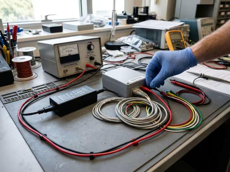
When bench and lab numbers disagree, the cause is usually the measurement. I see four problems again and again:
- Wrong reference. The team measures to bench ground, not protective earth, or floats the device on an isolation transformer.
- Wrong instrument. A multimeter isn’t a leakage tester. IEC 60601-1 requires a specific measuring network that models the human body.
- Low-frequency blind spots. Many meters roll off well below switching frequency and miss common-mode current from your converters.
- Missed summing. The lab connects all patient connections of an applied part together. Five ECG leads at 3 µA each total 15 µA, enough to fail a 10 µA CF limit.
My fix is simple. Put a proper leakage tester and a 110% mains source on your bench early. Test the finished configuration with every cable connected.
The Trade-Off: Better EMC, Stronger Isolation, Higher Leakage?
This is where most medical power projects stall. You fix emissions, and leakage climbs. You strengthen the barrier, and size or noise grows. Every choice moves at least two numbers.
Here’s how those trade-offs play out, and how I help teams manage them before they turn into a redesign.
The EMI Filter Fixes One Problem and Feeds Another
When a prototype fails conducted emissions, the quick fix is a bigger Y-capacitor. The scan turns green. The leakage meter tells a different story. At 264 VAC and 60 Hz, a 2.2 nF Y-cap passes about 220 µA, and a 4.7 nF part passes about 470 µA. Both sit far above a 100 µA touch current limit.
A stronger EMI filter can solve an emissions problem while quietly creating a leakage problem.
So I reach for other tools first:
- A larger common-mode choke cuts noise without adding leakage, at the cost of board space.
- X-capacitors handle differential noise and add no earth leakage.
- Tighter switching loops lower noise at the source, so the filter has less to do.
Class II supplies need extra care. With no earth, the Y-cap often bridges primary to secondary, and its current flows toward the enclosure or the patient side.
Transformer and Topology Choices Pull Both Ways
The transformer sets both your barrier and much of your coupling capacitance.
Interleaved windings cut leakage inductance and raise efficiency. They also raise interwinding capacitance. Triple-insulated wire and wider spacing help meet 2xMOPP and cut capacitance, but they make the part larger and add ringing, which can push you back toward a bigger filter. A shield winding between primary and secondary returns much of the switching current to the primary side. It often saves you a Y-cap.
Topology matters too. A flyback’s hard edges drive current across the barrier. A resonant LLC stage switches more softly, which helps EMC, but it can raise internal working voltage. Check what the barrier must truly withstand.
Smaller and More Efficient Makes Leakage Harder
Customers want compact, efficient supplies. Those goals push hard against leakage limits.
Smaller transformers leave less room for spacing, so capacitance rises. Higher switching frequency shrinks magnetics but adds more edges per second. GaN devices switch very fast, and faster edges drive more common-mode current through the same capacitance.
A 2xMOPP claim on paper does not guarantee a comfortable leakage margin in the finished device. Two supplies with identical ratings can differ several times over in barrier capacitance. Always ask for the primary-to-secondary capacitance figure.
Set the Leakage Budget Before You Pick Parts
Leakage current is not something you measure at the end. It is something you budget at the start.
Take your strictest limit, such as 100 µA for a BF part. Reserve about 30% for 110% mains, single-fault tests, and production spread. Then split the remaining 70 µA across every source: input Y-caps, transformer and DC-DC barrier capacitance, cables and shields, and external ports.
Now every part has a target. If the filter needs 2.2 nF, you know at once the budget can’t take it. You switch to a larger choke or a shielded transformer while the design is still on paper.

A Practical Workflow to Get Both Right
Knowing the trade-offs is one thing. Managing them takes a fixed order of work. I use the same five steps with every client, and each one produces an output the next step depends on.
1. Define the Environment, Class, and Applied Part
Pin down three facts on one page: where the device runs (hospital, home, or transport), whether it’s Class I or Class II, and every applied part marked as B, BF, or CF. Circle the strictest one.
Here’s a typical case. A home sleep therapy device has a BF sensor in the mask. Home use brings in IEC 60601-1-11, and many homes lack a reliable ground. That points to a Class II design with a 100 µA patient leakage target.
2. Set the Isolation Map and Leakage Budget Together
Draw an isolation map. Mark every barrier, the stage that provides it, its MOPP or MOOP count, its working voltage, and its test voltage.
Then build the budget against your strictest limit. For a CF front end, it might look like this:
- 10 µA limit, about 7 µA usable after margin
- Isolated DC-DC barrier: 2 µA
- Patient cable and shield: 2 µA
- Front-end parasitics and layout: 2 µA
- Reserve for accessories: 1 µA
Check the two documents against each other. If the map splits protection between stages, the budget must reflect each barrier’s capacitance.
3. Select Parts That Match the Real Use Case
With targets set, the catalog becomes a filter. Screen each candidate on working voltage, standard edition, conditions of acceptability, primary-to-secondary capacitance, and leakage data from a configuration close to yours.
Mismatches hide here. A supply certified at 50°C with forced air doesn’t fit a sealed, fanless housing that reaches 60°C inside. If a part forces you to rewrite your budget, drop it.
4. Pre-Test Before Layout and Filters Freeze
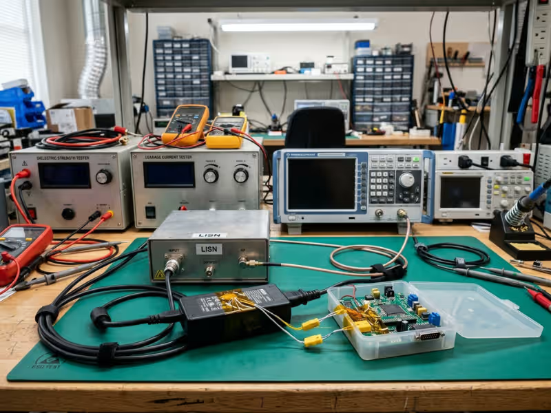
Build the first powered prototype with the real enclosure, cables, and accessories. Run leakage at 110% mains with open earth, open neutral, and mains on the applied part. Scan conducted emissions from 150 kHz to 30 MHz, aiming for at least 6 dB of margin. Hipot each barrier at its assigned rating.
Test emissions and leakage on the same build, on the same day. Finish before PCB release and enclosure tooling.
5. Build the Documentation Trail Early
Collect evidence as you go: the isolation map and budget with revision dates, supplier reports with conditions flagged, pre-compliance results, ISO 14971 risk entries for each barrier, and PCN agreements.
Labs don’t just ask what you chose. They ask why. A three-line note explaining why you capped the input filter at 1 nF can save a week of back-and-forth.
Common Mistakes That Delay Certification
Most delays don’t start in the test lab. They start months earlier, with an assumption nobody checked. These six appear in almost every review I run.
1. Treating the isolation rating as the whole compliance story
What teams think: The supply says 2xMOPP, so patient protection is covered.
What actually happens: The lab checks the whole path from mains to patient. A test point or copper pour that cuts creepage below spec fails hipot, even with a well-rated supply.
2. Assuming supply leakage equals system leakage
What teams think: The supply reads 40 µA, so the device will stay under 100 µA.
What actually happens: DC-DC stages, cables, shields, and data ports each add current. The total, not the supply alone, decides the result.
3. Reading hipot numbers without working-voltage context
What teams think: 4,000 VAC means 2xMOPP.
What actually happens: That figure applies only at a stated working voltage and test duration. Internal peaks and short production tests can make the number meaningless.
4. Leaving leakage budgeting until bench testing
What teams think: We’ll measure once the prototype runs and adjust.
What actually happens: The filter, layout, and enclosure are already frozen. Any fix, from a larger choke to a shielded transformer, now means a respin.
5. Reusing industrial or consumer supplies to save cost
What teams think: A good ITE supply plus an extra isolation stage costs less.
What actually happens: Most ITE supplies follow IEC 62368-1, with MOOP-level isolation and larger filter capacitance. Touch current can reach 250 µA or more, and you lose the medical component report. Extra testing usually wipes out the savings.
6. Ignoring edition, scope, and change control
What teams think: The supply has a certificate, so that part of the file is done.
What actually happens: The report covers an older edition, assumes conditions your enclosure breaks, or the vendor quietly swaps a transformer core. Your certified design no longer matches what ships.
All six share one root cause: teams pick parts first and check isolation and leakage later.
What to Ask a Medical Power Supply Vendor
A datasheet shows what a vendor wants you to see. The right questions show what you’ll actually get. I send the same list to every supplier on a shortlist, so I can compare answers side by side.
- Which IEC 60601-1 edition and amendment does the report cover? Also ask about national versions, such as ANSI/AAMI ES60601-1 or EN 60601-1.
- Can you send the full test report? The CB report shows the insulation diagram, measured spacing, leakage results, and conditions of acceptability. A one-page certificate doesn’t.
- What working voltage does each barrier support? Ask about primary-to-secondary, primary-to-earth, and secondary-to-earth separately, with the MOPP or MOOP count for each.
- What are the primary-to-secondary capacitance and total Y-capacitance? These two figures tell you how much of your budget the supply will use.
- How did you measure leakage? Ask for results at 110% mains, in normal and single-fault conditions, with the proper measuring network and the output cable connected under load.
- What is your change-control and end-of-life policy? Ask for a written PCN policy with at least six months’ notice, the changes that trigger it, last-time-buy terms, and ISO 13485 status.
- Does the supply suit home use or patient contact? For home devices, confirm Class II construction and Class B emissions. For patient-contact products, ask whether a low-leakage version supports your BF or CF target.
Pay attention to how each vendor answers. A supplier who sends clear data within days, and who can show controlled production through qualified facilities, usually supports you well through certification. One who needs three weeks to find a report will likely move just as slowly when your auditor calls.
FAQs
What is the difference between 2xMOPP and 2xMOOP?
Both provide two means of protection, but for different people. 2xMOOP protects operators, who touch the enclosure and can pull away. 2xMOPP protects patients, who may be sedated or wired to sensors. At 250 VAC, typical figures are 3,000 VAC and about 5 mm creepage for 2xMOOP, versus 4,000 VAC and about 8 mm for 2xMOPP.
Is a 2xMOPP transformer enough by itself?
No. The optocoupler, any Y-capacitor across the barrier, and the PCB spacing around them must meet the same rating. One short path from a via, copper pour, or mounting screw can undo a well-rated transformer. Check the whole barrier on the real board.
How is patient leakage different from earth leakage?
Earth leakage flows through the protective earth conductor. Patient leakage flows from an applied part, through the patient, to earth. Typical limits differ hugely: about 5 mA for earth leakage in normal condition versus 10 µA for Type CF patient leakage. A design can pass one easily and fail the other badly.
Does a certified medical power supply make the end device compliant?
No. The certificate covers the supply under its own conditions. Your lab still tests the finished device with every cable, port, and accessory in place.
How does an EMI filter affect leakage current?
Y-capacitors cut common-mode noise by passing current to earth. As a common design reference, 1 nF at 264 VAC and 60 Hz passes about 100 µA. Settle Y-cap values with both your EMC and safety engineers, and lean on chokes and layout where you can.
Does home healthcare use change the isolation target?
The MOPP rules stay the same, but the assumptions shift. IEC 60601-1-11 expects lay users and outlets that may lack a working ground, so an open earth becomes a likely condition. That’s why I steer home devices toward Class II designs. Stricter home EMC levels, including Class B emissions and 10 V/m radiated immunity, also add pressure on the leakage budget.
Can an industrial power supply be used if extra isolation is added?
Yes, but it rarely saves money. You must prove the full system meets IEC 60601-1, and industrial supplies often carry larger filter capacitance that keeps touch current high. Most teams find a medical-grade supply cheaper once they count the full validation effort.
Map the Barrier and Budget the Leakage Before You Pick a Supply
IEC 60601 defines the rules, isolation builds the barrier, and leakage current reveals whether the whole system still behaves safely. All three must hold up on the finished device, not just on a datasheet.
Projects stall when teams handle them separately. The EMC fix raises touch current. The compact layout shrinks creepage. The lab finds the gap, and the documents no longer match the board.
So start with two pages. On the first, draw an isolation map with every barrier, its rating, its working voltage, and the part that provides it. On the second, build a leakage budget that gives each source a share and keeps about 30% in reserve.
Then choose the power supply that fits both pages, whether from your current shortlist or a broader range of power products. If you’re starting a new design, sketch that map and budget this week. It’s the cheapest point to catch a problem.