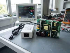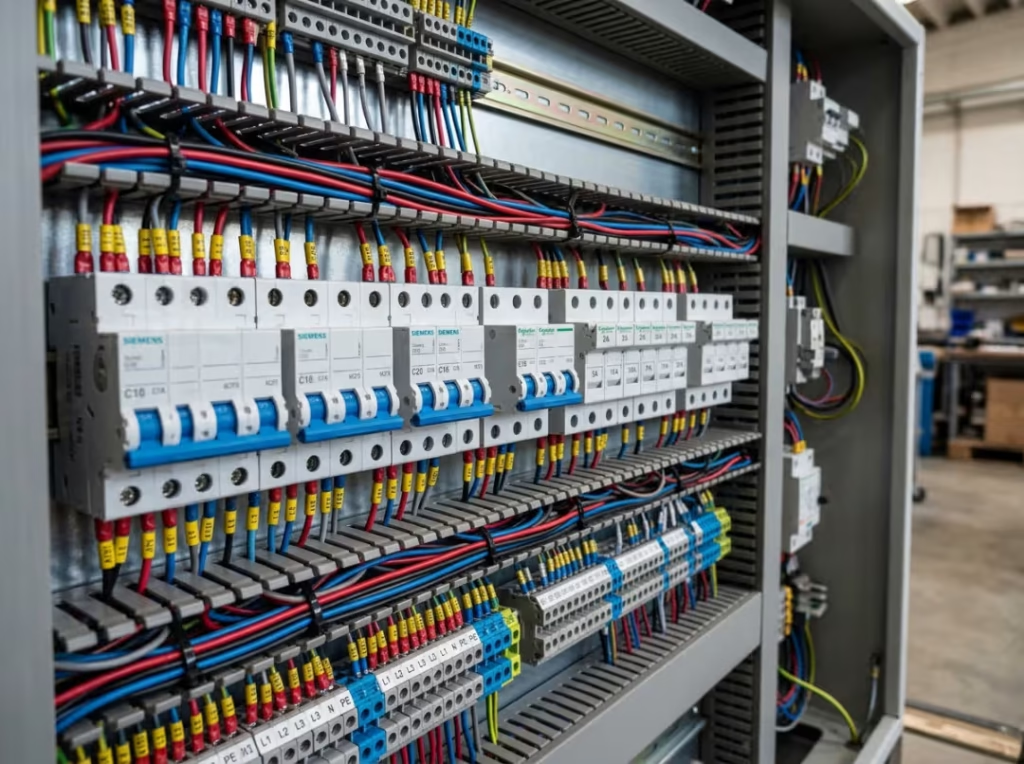
When the current in a circuit exceeds its safe operating limit, something has to stop it before the wiring overheats, the insulation burns, or someone gets hurt. That job belongs to overcurrent protection — and the device performing it is usually a fuse, circuit breaker, relay, or ground-fault interrupter.
This guide covers what overcurrent protection is, the three conditions that trigger it, how the main device types compare, and how to choose the right one for your application.
What Is Overcurrent Protection?
Overcurrent protection is the function of detecting excessive current in a circuit and interrupting it before it damages equipment or endangers people.
Two terms are often used interchangeably, but they mean different things:
- Overcurrent protection (OCP) is the function — the strategy of limiting current to a safe level.
- An overcurrent protection device (OCPD) is the hardware — the fuse, breaker, relay, or GFI that actually performs that function.
Excess current is dangerous for two distinct reasons. First, it generates heat. Heat degrades insulation, melts conductors, and can ignite surrounding materials. Second, uncontrolled current through an unintended path can deliver a lethal shock. Any protection scheme worth implementing has to address both risks — equipment and people.
How Does Overcurrent Protection Work?
Every overcurrent protection scheme follows the same sequence:
- The device carries or monitors the current in the protected circuit.
- Current exceeds the rated threshold — either gradually (overload) or instantaneously (fault).
- The device responds by melting a fuse element, tripping a breaker, or commanding a contactor to open.
- The circuit opens and current stops flowing.
- After the fault is cleared, a breaker or relay resets. A blown fuse must be replaced.
In regulated DC power supplies, overcurrent protection typically shows up differently. Under normal operation, the supply maintains a fixed output voltage — constant-voltage (CV) mode. When the load pulls more than the current limit, the supply shifts to constant current (CC) mode: it caps the output current at the set ceiling and lets voltage drop rather than tripping hard. This protects both the supply and the downstream load. Designing proper 5V and 12V power-supply protection requires understanding this behavior, not just sizing a fuse at the input.
Two key specs govern how any OCPD behaves during a fault:
- Trip curve (time-current characteristic): how quickly the device reacts at each level of overcurrent. Small overloads may take seconds or minutes; a hard short trips the device almost instantly.
- Response time: the raw speed from threshold crossing to circuit interruption.
Engineers use both to balance fast fault clearing against nuisance tripping on startup surges or brief transients.
What Causes an Overcurrent?
Overcurrent is a category, not a single event. Three different conditions fall under it, each with different causes, speeds, and risks.
Overload
An overload occurs when a circuit carries more current than its rated capacity along a normal current path. This happens when too many loads share a circuit, or when a single device draws more than expected — for instance, a motor driving a jammed conveyor. As mechanical resistance builds, the motor draws increasing current to maintain torque. Left uncleared, that elevated current overheats the windings.
Overloads build gradually. A well-designed protective device is meant to tolerate brief overloads and only trip if the condition persists — which is exactly why thermal breakers and time-delay fuses exist.
Short Circuit
A short circuit forms when current finds an unintended low-resistance path, bypassing the normal load entirely. Damaged insulation, a conductor touching a metal frame, or a pinched wire are common causes.
The current surge is almost instantaneous and often many times the circuit’s rated level. This is the key distinction from an overload: the speed and magnitude of a short circuit require near-immediate interruption. Without it, arcing and fire follow within seconds.
Ground Fault
A ground fault is a specific type of short circuit where current takes an unintended path to ground. It commonly appears in wet environments or where wiring insulation has degraded.
The primary hazard is shock. Even a small leakage current through a person’s body — as little as a few milliamperes — can cause injury or cardiac arrest. Standard fuses and breakers don’t react fast enough or at low enough current levels to provide meaningful shock protection. That’s why dedicated ground fault interrupters exist.
Overload vs. Short Circuit vs. Ground Fault
Not every overcurrent condition calls for the same protection strategy. The table below shows how they differ:
Condition | Cause | Speed of onset | Main risk | Typical protection |
|---|---|---|---|---|
Overload | Excess sustained current on a normal path | Gradual | Overheating, insulation damage | Breaker, time-delay fuse, relay |
Short circuit | Low-resistance fault path | Instant | Arcing, fire, equipment destruction | Breaker, fast-acting fuse |
Ground fault | Unintended current path to ground | Fast | Electric shock | GFI / GFCI |
The differences matter during device selection. A time-delay fuse that tolerates motor inrush is the wrong choice for a circuit where fast short-circuit clearing is critical. A standard breaker offers no meaningful protection against ground-fault shock.
Types of Overcurrent Protection Devices
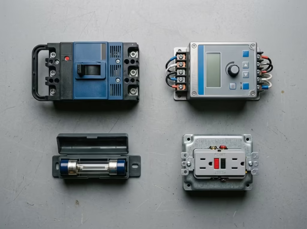
Four device families cover most overcurrent protection needs. They differ in how they work, whether they’re reusable, and where they fit best.
Fuses
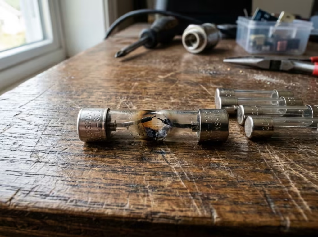
A fuse contains a calibrated metal element that melts when current exceeds its rated level. Once it opens, the circuit is broken.
How they work: The element absorbs the fault energy and sacrifices itself to interrupt the circuit. The response is purely physical — no electronics, no moving parts.
Where they fit best: Simple circuits, cost-sensitive designs, and applications where very fast clearing matters more than reset convenience. Different fuse classes — fast-acting, time-delay, semiconductor — exist because different loads have very different current profiles.
Key limitation: Single use. A blown fuse must be physically replaced, which means downtime and access to the panel. In installations where faults are expected to recur, this can become a maintenance burden.
Circuit Breakers
A circuit breaker is a resettable switching device that trips when it detects an overload or short circuit, then can be reset manually once the fault is cleared.
How they work: Thermal breakers use a bimetallic strip that deflects with heat — suited for slow overloads. Magnetic breakers respond to the strong magnetic field of a fault current surge — suited for fast short-circuit clearing. Thermal-magnetic breakers combine both mechanisms, which is why they’re standard in most panel applications.
Where they fit best: Residential panels, commercial distribution boards, and industrial branch circuits where resettability and consistent protection are both needed.
Key limitation: More expensive than fuses for equivalent ratings. In circuits with very high available fault current, the breaker’s interrupting capacity must be carefully matched — a breaker rated below the available fault current can fail catastrophically.
Relays
A protective relay senses electrical conditions in a circuit and commands an upstream breaker or contactor to open when specified thresholds are exceeded. It doesn’t interrupt the circuit directly.
How they work: The relay monitors parameters — current magnitude, overcurrent duration, phase imbalance — and triggers the switching device when conditions fall outside set limits. Modern digital relays can monitor multiple parameters simultaneously and be programmed for application-specific behavior.
Where they fit best: Motors, motor control centers, industrial automation, and power distribution systems where simple magnitude-based protection isn’t enough and coordination between multiple devices matters.
Key limitation: More complex to commission and coordinate than fuses or breakers. Relay-based systems require careful settings, maintenance, and testing — and they rely on a properly functioning upstream switching device.
Ground Fault Interrupters (GFI / GFCI)
A GFI monitors the current balance between the outgoing and return conductors. Any imbalance — current leaking to ground — triggers an almost instantaneous trip.
How they work: The device compares the current on the hot and neutral (or L1 and L2) conductors. A difference of roughly 4–6 mA indicates leakage, and the device opens within milliseconds. This is far faster and far more sensitive than any standard OCPD.
Where they fit best: Wet areas, outdoor installations, and anywhere human contact with energized equipment is possible — kitchens, bathrooms, construction sites, and outdoor receptacles.
A note on terminology: GFCI (ground-fault circuit interrupter) is the common name for the outlet or breaker version used in buildings. GFI is often used more broadly to refer to the same protective function in industrial or equipment contexts. The operating principle is the same.
Key limitation: GFCIs protect against shock, not overloads or short circuits. They work alongside standard OCPDs, not instead of them. Industrial POE systems and outdoor surveillance equipment — which carry both power and data over copper — often require a combination of surge and ground fault protection to cover the full range of hazards.
Device Comparison
Device | Reusable | Response speed | Best for | Key selection specs |
|---|---|---|---|---|
Fuse | No | Very fast | Simple, cost-sensitive, fast-clear circuits | Rated current, interrupting rating, class |
Circuit breaker | Yes | Fast, adjustable | Panels, commercial and industrial branch protection | Trip curve, interrupting capacity (AIC) |
Relay | Yes | Programmable | Motors, automation, power distribution | Parameters monitored, coordination settings |
GFI / GFCI | Yes | Near-instant (≈ 4–6 mA threshold) | Shock protection in wet or high-contact areas | Leakage current sensitivity |
How Do You Choose the Right Overcurrent Protection Device?
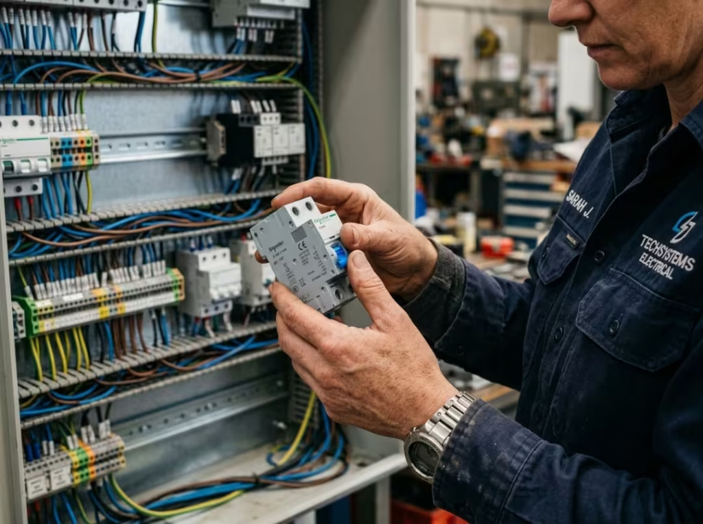
Device selection is an engineering decision, not a catalog lookup. The right answer depends on the load type, the fault environment, the operating conditions, and what happens downstream when a trip occurs.
Start with These Six Parameters
Before choosing any device, establish:
- Rated current: the maximum continuous current the circuit is expected to carry.
- Interrupting capacity (AIC): the maximum fault current the device can safely clear. This is not the same as the rated current — available fault current at the installation point can be thousands of amps, and the device must handle it without failure.
- Trip curve / time-current characteristics: the relationship between overcurrent magnitude and trip time. This determines whether the device will tolerate motor inrush, startup surges, and brief transients without nuisance tripping.
- Response time: how fast the device must clear to protect downstream equipment.
- Voltage rating: the device must be rated for the circuit’s operating voltage, not just its current.
- Operating environment: elevated ambient temperature reduces a device’s continuous current rating. Vibration can affect mechanical breakers. Humidity and contaminants matter in enclosure design.
Match the Device to the Load
Here is the practical decision logic most engineers follow:
- PCB and low-voltage electronics → Fast-acting fuses or solid-state OCP. The priority is protecting components before thermal damage accumulates. CV-to-CC limiting in the power supply often provides the first layer; a fuse on the input or output handles catastrophic faults.
- Motors and motor circuits → Time-delay fuses or thermal-magnetic breakers sized for inrush current. A device sized only for running current will trip every time the motor starts. The inrush during startup can be 5–10× the full-load current for several seconds.
- Industrial control cabinets → Branch breakers or supplementary protectors on each branch circuit, coordinated so a fault on one branch doesn’t affect the rest.
- Wet or high-contact environments → GFCI protection is required regardless of what other OCPDs are in the circuit. Standard breakers don’t react fast enough at the leakage current levels that injure people.
- Power distribution systems → Breakers selected and set for selective coordination, so only the device nearest a fault trips. Without coordination, a branch fault can take out an entire distribution board.
Common Selection Mistakes
These errors show up consistently in real installations:
Undersizing interrupting capacity. If the available fault current at the installation point exceeds the device’s AIC, the device can fail violently — rupturing, arcing, or starting a fire instead of clearing the fault. AIC must always exceed the available fault current.
Ignoring motor inrush. A device sized for running current will trip on every startup. Time-delay devices and the NEC’s motor protection sizing rules exist precisely to handle this.
Skipping ambient temperature derating. A breaker or fuse rated for 30 °C may carry less current reliably at 50 °C inside an enclosure. Manufacturer derating curves apply.
Assuming one device covers all failure modes. A standard breaker handles overloads and short circuits. It does not provide meaningful ground-fault shock protection. A GFCI handles ground faults. It is not a substitute for overcurrent protection. Many installations need both.
How Do You Size an Overcurrent Protection Device?
The calculation is straightforward once you know the load type and operating pattern.
Find the Load Current
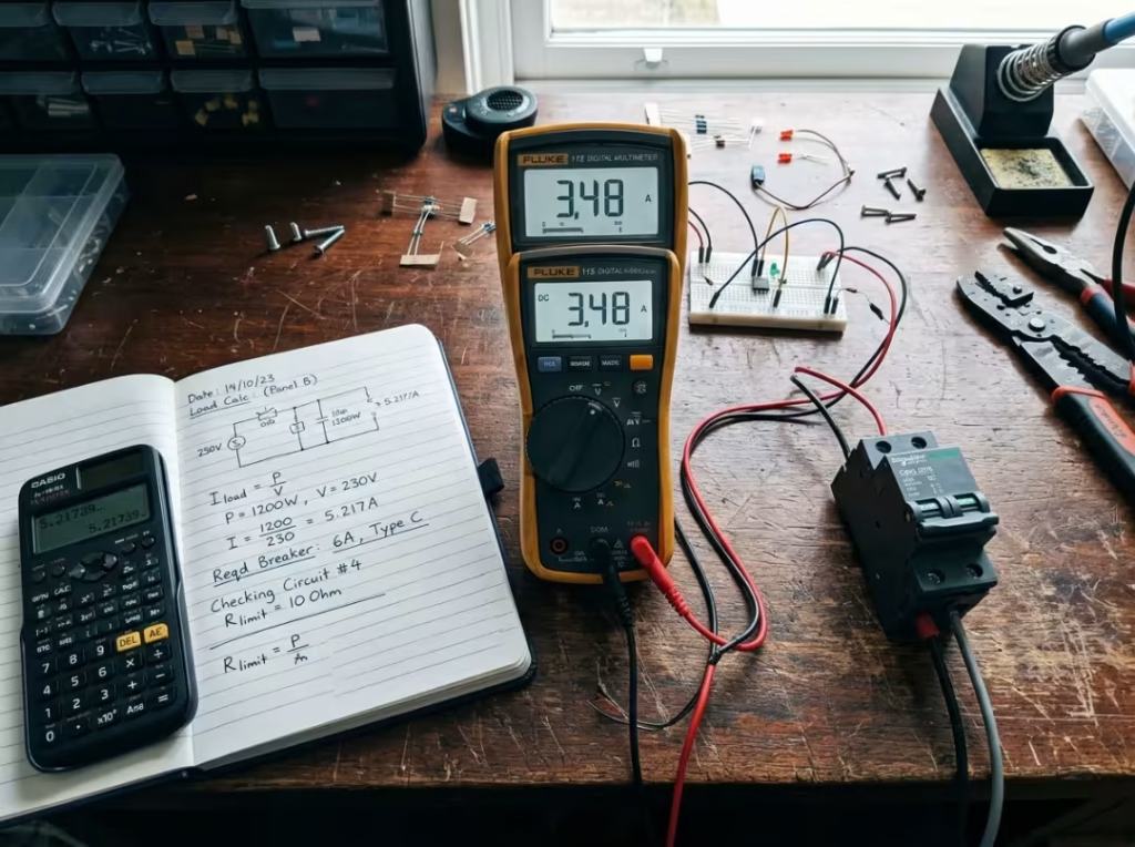
Start with: Current (A) = Power (W) ÷ Voltage (V)
A 1,200 W load on a 120 V circuit draws 10 A. That’s your baseline.
Apply the Right Rating Factor
- Continuous loads (operating 3 hours or longer): size the OCPD at 125% of the load current. A 10 A continuous load needs a device rated for at least 12.5 A — select the next standard size up.
- Noncontinuous loads (operating less than 3 hours): size at 100% of the load current.
- Motor loads: NEC motor protection sizing uses full-load amps (FLA) and service factor.
- Service factor ≤ 1.15: FLA × 1.25 (a 20 A FLA motor → 25 A)
- Service factor > 1.15: FLA × 1.15 (a 20 A FLA motor → 23 A)
Adjust for Ambient Temperature
Device ratings assume standard ambient conditions — approximately 30 °C (86 °F). In a hot enclosure, derate per the manufacturer’s correction curves. Don’t assume the nameplate current rating holds at elevated temperatures; it doesn’t.
Coordination, Trip Curves, and When They Matter
For single-device circuits, basic sizing is enough. For systems with multiple OCPDs in series — distribution boards, motor control centers, multi-branch panels — three additional concepts matter.
Trip curve selection: Every device has a time-current characteristic that shows how quickly it trips across the range of possible overcurrents. Selecting the wrong curve — too fast or too slow — causes either nuisance tripping on normal load variations or inadequate protection during sustained faults.
Selective coordination: When a fault occurs on one branch, only the device directly upstream of that fault should trip. If upstream devices also trip, more of the system goes down than necessary. Proper coordination means setting trip curves so each downstream device always operates faster than the one above it at the fault current levels they share.
Zone-selective interlocking (ZSI): Used in larger systems with intelligent breakers, ZSI allows devices to communicate so the one nearest the fault clears it quickly while upstream devices hold. This keeps the rest of the installation energized during a fault and speeds fault clearance compared to traditional coordination alone.
A hospital distribution system is a practical case in point: a fault on one branch panel should not darken an entire floor. With proper coordination or ZSI, only the faulted branch drops out while everything upstream stays live.
Relevant Standards
Two bodies set the framework for overcurrent protection in North America. Their requirements are minimum baselines, not design targets.
National Electrical Code (NEC):
- NEC 110 requires OCPDs to have interrupting ratings sufficient to break available fault current at nominal circuit voltage.
- NEC 210.8(A)(7) mandates GFCI protection in specified locations, requiring trip below the marked leakage threshold — typically 6 mA — in milliseconds.
Underwriters Laboratories (UL):
- UL 2367 covers solid-state OCP devices for power supplies and batteries.
- UL 489 covers molded-case circuit breakers for residential, commercial, and industrial use.
- UL 1077 covers supplementary protectors used inside equipment enclosures.
A practical compliance checklist:
- All OCPDs accessible for inspection and service
- Interrupting ratings exceed available fault current at each installation point
- Device sizing matches conductor, panel, and equipment ratings
- Routine testing schedule documented
- Installation and modification records maintained for audit
Where Overcurrent Protection Is Applied
Every circuit that can carry a fault needs some form of overcurrent protection. The right device and configuration depend on the environment.
- Residential panels: Thermal-magnetic breakers on branch circuits; GFCI at kitchens, bathrooms, garages, and outdoor receptacles.
- Commercial buildings: Coordinated breaker schemes across distribution boards, with GFCI at required locations and arc-fault protection where mandated.
- Industrial machinery and motor control: Time-delay fuses and protective relays sized for inrush; relays monitoring current, phase balance, and temperature at motor control centers.
- Power supplies and electronics: Fast-acting input fuses combined with CV-to-CC current limiting in the supply and, where required, output-side solid-state OCP for sensitive loads. Proper OCP design in low-voltage DC systems — including 5V and 12V rails — involves both hardware protection and supply-level current limiting working together.
- Industrial field networks: Equipment such as PoE adapters deployed in outdoor or industrial environments requires combined overcurrent and surge protection. The fault modes in these installations include external surges and lightning-induced transients, not just internal overcurrents.
- Medical, aerospace, and semiconductor equipment: These applications require well-coordinated protection with documented traceability. Relay-based schemes and carefully specified breakers are common, and any protection failure has consequences beyond the electrical system.

Frequently Asked Questions
What is the difference between overcurrent protection and an overcurrent protection device (OCPD)?
Overcurrent protection is the function — detecting and interrupting excess current. An OCPD is the hardware that performs that function. The protection strategy is the objective; the device is the means.
How do I decide between a fuse and a circuit breaker?
Use a fuse when cost, fast response, and simplicity matter more than reset convenience. Use a circuit breaker when the circuit may trip repeatedly, resettability is operationally important, or adjustable trip settings add value. For circuits that fault occasionally and need manual investigation before restore, either can work; the operating context usually makes the answer clear.
What is the difference between an overcurrent and an overload?
An overload is one type of overcurrent — excess current through a normal path that builds up gradually. Overcurrent also includes short circuits (a sudden, massive surge through a fault path) and ground faults (leakage to ground). Every overload is an overcurrent, but most overcurrents are not simple overloads.
How do I size an OCPD correctly?
Calculate load current first. Apply 125% for continuous loads, 100% for noncontinuous loads, and the NEC motor sizing rules (FLA × 1.25 or FLA × 1.15, depending on the service factor) for motors. Then derate for ambient temperature and confirm the interrupting rating exceeds available fault current.
What is interrupting capacity (AIC), and why does it matter?
AIC is the maximum fault current the device can safely clear. If available fault current exceeds the AIC, the device fails — often violently. This spec is frequently overlooked during selection, particularly on circuits close to the service entrance where available fault current is highest.
What is a trip curve, and how do I read one?
A trip curve is a log-log plot showing how long a device takes to operate at each overcurrent level. Higher overcurrent means faster tripping. Reading the curve tells you whether the device will tolerate motor startup inrush, clear sustained overloads within a safe thermal window, and respond instantaneously to short-circuit levels.
Does a standard OCPD also protect against ground faults?
No. Standard fuses and breakers protect against overloads and short circuits. They don’t react at the current levels — a few milliamperes — that pose shock risk. Ground fault protection requires a GFI or GFCI specifically designed for that threshold.
When do I need selective coordination?
Whenever the continuity of upstream circuits must be maintained during a downstream fault. Data centers, hospitals, manufacturing lines, and any facility where a single fault should not take down an entire section all need coordinated protection. NEC also mandates coordination in certain critical circuits.