Buying a switched mode medical power supply is not like buying an industrial or consumer unit. A wrong choice costs more than a few points of efficiency. It can raise leakage current, break EMC margins, delay approval, and force a late redesign.
I often see buyers compare wattage, size, and price first. Those points matter, but they do not tell the full story.
This checklist shows you which specs buyers misread most often. It also covers the documents to request early and the evidence you need before you shortlist any supplier.
Why Buying a Medical Switched Mode Power Supply Is Different
In most industrial projects, a power supply only has to deliver clean, stable power. In a medical device, it also has to protect a person who may be sedated, wired to sensors, or unable to move away from a fault. That one difference changes how you should buy.
Patient contact raises the stakes first. An ECG lead, SpO2 clip, or blood pressure cuff can connect the patient to your device’s electronics. A healthy adult barely notices a few hundred microamps. A patient with electrodes on the chest faces far greater risk from the same current.
So medical limits on touch and patient leakage run much tighter than the rules for ITE power supplies. They often sit at 100 µA or less in normal condition.
Regulatory review adds a second layer. Your test lab or notified body will not just ask whether the supply works. It will ask how the supply was tested, which protection level it provides, and whether its report covers your use case. A supply without solid documentation can stall your whole submission, even when the hardware performs well.
Uptime matters more than many buyers expect. Hospitals run equipment around the clock, often in warm rooms and on shared power strips. A monitor that resets during a brief voltage dip doesn’t just annoy a nurse. It can interrupt a reading or trigger an alarm. You need thermal margin, hold-up time, and long-term reliability data, not just a wattage rating.
Then there’s system-level risk. Your supply is only one block in the device. Its leakage adds to the display, the embedded PC, and the EMI filter. A supply that barely passes alone can push the finished device over its limit.
This is why a high-quality industrial PSU rarely works as a shortcut. Many industrial units offer reinforced insulation and good EMC. But they usually test to 3,000 VAC isolation rather than the 4,000 VAC that 2 x MOPP requires. They also allow higher leakage and come with reports written for a different standard. Closing those gaps usually costs more time than choosing a proper medical supply from the start.
Start Here: What Actually Makes a Power Supply Suitable for Medical Use?
“Medical grade” shows up on almost every datasheet I review. It sounds reassuring, but it has no fixed definition. No standard uses the phrase, and no lab tests for it.
What matters is narrower and more useful. Does this supply fit your device, your patient connection, and your approval path? Three questions answer that, and none of them depends on a label.
“Medical Grade” Is Not the Same as “Right for Your Device”
A supply can carry a genuine IEC 60601-1 certificate and still be the wrong choice for your product. The certificate shows the supply passed testing under its own conditions. It doesn’t show that those conditions match yours.
Here’s a common case. A buyer selects a certified 2 x MOOP adapter for a bedside monitor with SpO2 and ECG inputs. The adapter is fully legitimate. But the patient-side barrier now has to come from somewhere else, usually an extra isolated stage inside the device. That means added cost, board space, and leakage the team never planned for.
So start with your own device, not the supplier’s catalog. Ask yourself three things first:
- Does any part of my device touch the patient?
- Is that contact BF, CF, or none at all?
- Where in my system does the patient protection barrier sit?
Once you know those answers, the supplier list gets much shorter.
Why MOPP, Leakage, and Test Evidence Matter More Than a Label
The label is a claim. The specs and reports are the proof. I tell buyers to check three things before they look at price.
Protection level. MOPP (Means of Patient Protection) covers patient safety. MOOP (Means of Operator Protection) covers the operator. A 2 x MOPP supply passes a 4,000 VAC isolation test and uses wider creepage distances. If the supply forms part of the patient barrier, 2 x MOPP is usually the safe baseline.
Leakage figures. Look for maximum touch current at 264 V and 60 Hz, in both normal and single-fault conditions. A “typical” value at 115 V tells you very little about how the supply will perform in the lab.
Test evidence. Ask for the full test report, not just a summary page. The report shows the measured values, the test conditions, and the conditions of acceptability. Those conditions may require an earth connection, a certain enclosure, or a set mounting position in your device.
When all three line up with your application, you have a suitable supply. When one is missing, you have a marketing claim.
Certified Supply vs. “Designed to Meet” the Standard
This distinction catches more buyers than any other. The two phrases sound similar, but they carry very different weight with your lab.
A certified supply has been tested by an accredited third-party lab. It comes with a CB test certificate and a full report, and often with national marks such as UL or TÜV. Your lab can review that report and accept much of it. That saves you time and test fees.
A supply that is “designed to meet” or “compliant with” IEC 60601-1 has usually only been reviewed by its own maker. No independent lab has checked it. Your lab will then have to test the supply as a part of your device. That can mean extra dielectric, leakage, and temperature tests, plus a longer schedule and a larger bill.
I’ve seen a low-cost “designed to meet” adapter add six weeks to a project. It failed creepage inspection at the system lab. The savings on the unit price disappeared long before launch.
My advice is simple. If a supplier uses “designed to meet,” ask for the CB certificate number and the name of the issuing lab. A certified supplier will send both right away. If you get a vague answer, treat the supply as uncertified and plan your budget and timeline around that.
The Specs Buyers Misread Most Often
Most bad supply choices start with a number that looked right. The datasheet shows a value, the buyer checks it against a target, and nobody asks how the supplier got that value.
Five specs cause most of the trouble I see. Each one looks simple on paper. Each one hides a condition that can change the result in your lab.
Leakage Current: The Risk Buyers Find Last
Leakage current rarely fails at the bench. It usually fails at the safety lab, weeks after you’ve committed to the part.
Datasheets often list three different figures, and buyers tend to treat them as the same thing:
- Earth leakage flows into the protective earth wire. The limit for the finished device is 5 mA in normal condition, so this number looks comfortable.
- Touch current flows from the enclosure through a person. The limit is 100 µA in normal condition and 500 µA in single fault.
- Patient leakage flows through an applied part into the patient. It’s 100 µA for BF parts and only 10 µA for CF parts.
Here’s the trap. An industrial-style datasheet might say “earth leakage < 300 µA.” That looks tiny next to 5 mA. But when the lab opens the earth wire, that same 300 µA becomes touch current. Now it has used most of your single-fault budget before anything else in your device leaks.
Two more details change the picture:
- Test voltage. A figure measured at 115 V roughly doubles at 264 V, which is the voltage your lab will use.
- System total. The limit applies to your finished device, not to the supply. Your display, embedded PC, and EMI filter all add to the total.
I ask every supplier for maximum touch current at 264 V and 60 Hz, in normal and single-fault conditions. If the supply uses more than about half your device limit, I keep looking.
MOPP vs. MOOP: Ask Where the Barrier Sits
Protection level sounds like a yes-or-no spec. In practice, it depends on where the supply sits in your system.
MOOP protects operators, such as nurses and technicians. MOPP protects patients. MOPP sets stricter rules because patients may be connected to the device and can’t move away from a fault.
Here’s how the three most common ratings compare in practice:
Rating | Isolation Test | Creepage (approx., 250 V) | Typical Fit |
|---|---|---|---|
2 x MOOP | 3,000 VAC | ~5 mm | Lab analyzers, centrifuges, devices with no patient contact |
1 x MOPP | 1,500 VAC | 4 mm | Primary to earth on Class I designs |
2 x MOPP | 4,000 VAC | 8 mm | Supplies that form the patient barrier |
The rating alone doesn’t decide your choice. The location of your patient barrier does.
If your device has its own medical-grade isolated stage between the supply and the applied part, a 2 x MOOP supply may work. If the supply’s own transformer forms the only barrier between mains and the patient, you need 2 x MOPP.
So I never ask a supplier “Is it MOPP?” first. I sketch the path from mains to the patient connection and mark every isolation stage on it. Then I ask which stage this supply must cover. That one drawing prevents more wrong orders than any spec sheet.
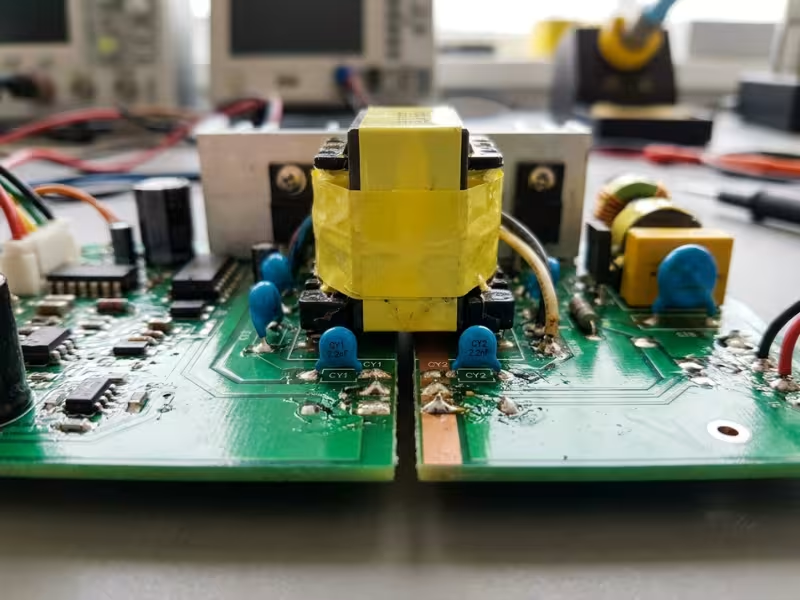
Ripple, Noise, and Output Accuracy: Check the Method
Ripple and noise numbers look easy to compare. They aren’t. Two suppliers can test the same supply and report figures that differ by 2x.
The method behind the number matters more than the number. Look for these details:
- Bandwidth limit. Most suppliers measure with a 20 MHz scope limit. A full-bandwidth reading catches more switching spikes and reads higher.
- Capacitors at the probe. Many tests add a 0.1 µF ceramic and a 10 µF or 47 µF electrolytic across the output. Those parts quietly filter the result.
- Probe technique. A short ground spring gives a clean reading. A long ground clip picks up noise and inflates it.
- Load and temperature. Ripple often rises at light load, full load, or low temperature.
If one supplier lists 100 mV p-p “with 0.1 µF and 47 µF” and another lists 150 mV p-p with no conditions, the second may actually perform better.
Output accuracy has a similar trap. A spec like “±1%” may cover only the factory setpoint. Total regulation also includes line, load, and temperature changes, and can reach ±3% or more. On multi-output supplies, check cross-regulation too. A light load on one rail can push another rail out of tolerance.
For sensitive front ends, such as ECG or ultrasound, I ask suppliers to measure ripple on my actual load. Then I compare their results with my own bench data before I trust either.
Thermal Performance and Derating: Your Enclosure Changes Everything
A supply’s power rating assumes airflow and ambient conditions your device probably doesn’t have.
Most derating curves start at full power up to 40 or 50°C. Then they drop linearly, often to 50% at 70°C. But the conditions behind that curve matter just as much:
- Open-frame units often assume a set airflow, such as 10 to 20 CFM, or free air with nothing nearby.
- Mounting orientation changes convection cooling. A board mounted on its side can run noticeably hotter.
- Enclosed systems trap heat. Inside a sealed cart or monitor housing, the local air often runs 10 to 15°C above room temperature.
That rise does more than cut available power. Electrolytic capacitor life roughly halves for every 10°C increase. A supply that lasts eight years on an open bench might last four inside your enclosure.
I ask suppliers for three things: the full derating curve with its test conditions, component temperatures at full load, and the conditions behind the MTBF figure. Then I measure the actual air temperature around the supply in my device before I size it. If the ambient reaches 55°C, I size for 55°C, not 25°C.
Hold-Up Time: Match It to Your Device
Hold-up time tells you how long the output stays in regulation after input power drops. Most datasheets quote 10 to 20 ms. The bigger question is under what conditions.
Suppliers often measure hold-up at 230 VAC and full load. At 100 VAC, the same supply may hold up for half as long. Always ask for the figure at your lowest rated input and your real load.
Your target depends on what your device must do during a voltage dip. IEC 60601-1-2 tests dips and interruptions, from a half cycle to five seconds. For each test, your device must keep basic safety and essential performance.
- A patient monitor usually can’t lose its display or data during a short dip. Plan for at least 20 ms at low line, with margin.
- A lab analyzer may tolerate a controlled restart if it recovers safely and loses no results.
- Life-support or critical-care devices shouldn’t rely on hold-up time at all. They need battery backup or a UPS-style design.
So don’t copy a hold-up target from your last project. Start with your device’s essential performance, then pick the hold-up time that protects it.
Which Compliance Evidence Should a Buyer Ask for Before Shortlisting?
A datasheet tells you what a supplier claims. The compliance file tells you what a lab actually measured. When I help a team shortlist suppliers, I ask for documents before I ask for prices. A supplier that can’t send them quickly usually can’t support your approval later either.
Not every document carries the same weight. Some prove a lot, and some prove very little. Here’s how I sort them.
The Minimum Document Set
Before a supply makes my shortlist, I want five documents in hand:
- The full IEC 60601-1 test report. This is usually a CB test report, often 80 to 150 pages long. It holds the measured leakage values, dielectric test results, creepage and clearance data, temperature readings, and the insulation diagram.
- The CB test certificate. This one-page summary links the report to a specific model, standard edition, and issuing lab.
- The IEC 60601-1-2 EMC test report. It shows the emissions results, the immunity levels applied, and the test setup.
- National certificates or listings. These include UL or cUL recognition for North America and any other marks your markets require.
- The Declaration of Conformity. It covers the directives and substance rules the supplier declares, such as low voltage, EMC, and RoHS.
Each document answers a different question. Use this table to see what each one confirms and where it stops:
Document | What It Confirms | What It Doesn’t Confirm |
|---|---|---|
IEC 60601-1 test report | Measured values, test conditions, MOPP/MOOP rating, conditions of acceptability | That the supply fits your device or your system leakage budget |
CB test certificate | A recognized lab tested this model to a stated edition | Any measured values or test conditions |
IEC 60601-1-2 EMC report | Emissions and immunity results for the supply on its own | That your finished device will pass EMC |
National listing (UL, TÜV) | Acceptance for a specific market | Coverage for markets the listing doesn’t name |
Declaration of Conformity | The supplier’s own statement on directives and substances | Independent testing of any kind |
Also check the edition on each report’s cover page. Most labs now expect IEC 60601-1 Edition 3.2, which includes Amendment 2. For EMC, they expect IEC 60601-1-2 Edition 4.1. An older report may still hold up, but your lab may ask for a gap review. That review costs you time.

Why a Certificate Alone Isn’t Enough
Many suppliers send the CB certificate and stop there. It looks official, and it is genuine. But it can’t help your engineers make a single design decision.
The certificate shows that a test happened. The report shows what the test found. You need the report for three reasons.
You need the real numbers. Your leakage budget depends on the measured touch current at 264 V. The certificate doesn’t list it. Only the report’s test tables do.
You need the conditions of acceptability. This section tells your lab what the supply still needs from your device. It might require a protective earth connection, a fire enclosure, a set mounting orientation, or repeat temperature tests in your final assembly. If you miss one of these, your lab will find it for you, usually at the worst time.
You need to confirm the scope. I’ve seen reports that cover only the 100–240 V model, or only one output voltage in a product family. If your exact model isn’t listed, the report doesn’t cover your part.
A quick tip: you can look up any CB certificate in the IECEE online database. Search the certificate number and confirm the model, the edition, and the issuing lab. It takes two minutes and catches the occasional outdated or misquoted certificate.
Don’t over-trust the Declaration of Conformity either. The supplier writes and signs it. It doesn’t prove medical safety, and it doesn’t replace a test report.
When Collateral Standards Also Matter
IEC 60601-1 covers basic safety. The collateral standards cover specific risks. Two of them matter most when you buy a supply.
IEC 60601-1-2 applies to almost every device. It sets emissions limits, usually CISPR 11 Group 1, and immunity levels for ESD, surge, fast transients, and voltage dips. A supply with its own EMC report gives you a head start. It does not certify your device.
Your system still needs its own test, because cables, enclosures, and other modules all change the result. What the supply’s report really gives you is margin. Ask how many dB below the limit the conducted emissions sit. Anything under 3 dB leaves you very little room.
IEC 60601-1-11 applies when your device goes home with a patient. Home use raises the bar in several ways:
- Higher immunity levels. Radiated immunity rises from 3 V/m to 10 V/m.
- Ingress protection. Your device needs an IP rating that suits a home setting.
- Mechanical strength. Adapters must survive drops and rough handling.
- Untrained users. Your design can’t count on a protective earth.
If your device will be used at home, ask the supplier whether the EMC report used home healthcare immunity levels. Also ask for the supply’s IP rating and drop test results. Many professional-use supplies don’t have them.
Other collateral standards, such as IEC 60601-1-8 for alarms, apply to the finished device rather than the supply. Your supplier doesn’t need to cover them.
My rule is simple. Send the document request list with your first inquiry. A strong supplier returns the full set within a few days. A supplier that answers with “available on request” three times should drop off your shortlist.
How to Compare Suppliers Beyond the Datasheet
Two suppliers can send you nearly identical datasheets and still deliver very different projects. One helps you pass the lab on the first try. The other leaves you chasing answers while your schedule slips.
The difference rarely shows up in the specs. It shows up in how each supplier works with you before and after the order. These are the six signals I check on every shortlist.
Application engineering support. Good support means a real engineer reviews your use case. Send a short brief that covers your applied part type, enclosure, ambient temperature, and load profile. A strong supplier replies with specific comments. They might flag a derating concern at 55°C or ask where your patient barrier sits. A weak supplier replies with a catalog link and a price. If nobody asks about your device, nobody will help when the lab finds a problem.
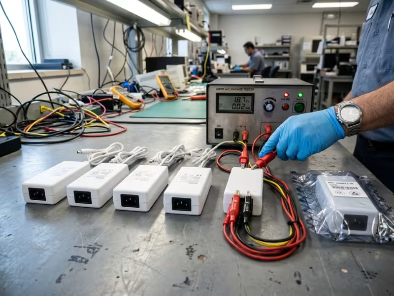
Sample consistency. Your samples often come from a pilot run, while your production units come from a full line. Ask the supplier to confirm that both use the same bill of materials, transformer source, and factory. When production starts, pull three to five units from the first lot. Then check touch current, output ripple, and hipot results against your sample data. A shift of 15 to 20% in leakage usually points to a component change. Keep one approved sample sealed as your reference unit.
Revision control. A supplier can swap a Y-capacitor vendor, change a transformer winding, or reroute a PCB trace without changing the part number. Any of these changes can move leakage by tens of microamps or shift conducted emissions by several dB. Ask how the supplier handles revisions. Look for three answers:
- A written Product Change Notification (PCN) process
- At least 90 days’ notice before any change that affects form, fit, function, or safety
- Updated test reports when a change touches the safety-critical parts list
If the supplier can’t explain its change process, assume changes happen without notice.
Lifecycle and end-of-life policy. Medical devices often stay in production for 7 to 10 years, and service support can run longer. A supply that goes obsolete in year three can force a redesign and a new round of testing. Ask directly how long the supplier commits to building the model. Also ask how much notice it gives before end of life and how long the last-time-buy window lasts. I look for at least 6 to 12 months of notice. Get the answer in writing, ideally in your supply agreement.
Response quality as a signal. How a supplier answers your early questions predicts how it will answer during a crisis. I track two things: speed and depth. A good supplier answers technical questions within two to three business days and attaches data. A weak one takes two weeks and sends a general reply. If you have to ask the same question three times, that pattern won’t improve after you sign a purchase order.
Vague claims as red flags. Certain phrases usually mean the evidence doesn’t exist yet. Treat these as open questions, not answers. The table below pairs each common claim with the follow-up I send:
Vague Claim | What to Ask Instead |
|---|---|
“Meets medical standards” | Which standard, edition, and certificate number? |
“Low leakage design” | What is the maximum touch current at 264 V and 60 Hz? |
“MOPP compliant” | 1 x or 2 x MOPP, and between which circuits? |
“Certification in process” | Which lab, and what is the expected completion date? |
“Reports available on request” | Please send them with your quotation. |
A supplier with real data will answer each follow-up in one email. A supplier without it will change the subject.
I score each shortlisted supplier on these six points before I compare prices. A supplier that costs 10% more but passes all six often saves you months later. The cheapest unit stops being cheap the first time your lab asks a question the supplier can’t answer.
Off-the-Shelf, Modified Standard, or Custom? Picking the Right Path
Most buyers treat this as a two-way choice: buy a catalog unit or build a custom one. A third path solves more projects than either. A modified standard unit keeps the certified core of a proven supply and changes only what your device needs.
I start every project the same way. I list the gaps between the best catalog unit and the device requirements. The length of that list usually makes the decision.
Off-the-Shelf: When the Fit Is Already There
A catalog supply makes sense when it meets your requirements with room to spare. I look for three signs:
- Its MOPP rating and leakage figures fit your applied part class with margin.
- Its form factor, connector, and cable already suit your enclosure.
- Your volumes are low, or your schedule is tight.
The benefits add up fast. Samples often ship within days. Production lead times usually run 4 to 8 weeks. The CB report already exists, so your lab can reuse most of it.
The trade-off is that you design around the supply. You may add an adapter cable, a mounting bracket, or an extra filter stage. Count those parts and the labor. Sometimes they cost more than a small modification would.
Modified Standard: Small Changes, Certification Mostly Intact
This path fits when a catalog unit covers 80 to 90% of your needs. Common changes include:
- A different DC connector or locking plug
- A longer or shorter output cable
- Lower leakage through reduced Y-capacitance
- A new enclosure color, label, or mounting tab
- A small output voltage trim
The key question is whether the change touches the safety-critical parts list. Cable length, connector type, and labeling usually don’t. The supplier can often update the report after a short review.
Changes to Y-capacitors, the transformer, or the enclosure do touch that list. They need new leakage and dielectric tests, often a conducted emissions check, and a CB report amendment.
Expect a modest engineering fee, often a few thousand dollars. First-lot lead times usually run 8 to 12 weeks. Minimum order quantities often rise to a few hundred or a few thousand units.
Before you approve a modification, ask the supplier one question in writing: “Which sections of the test report will this change affect?” A good supplier answers with section numbers, not reassurance.
Custom: When the Gaps Are Too Big to Patch
Custom becomes worth the effort when no catalog unit comes close. Three triggers come up most often:
- Unusual form factor. The supply must fit a handheld device, a wearable, or a tight space inside a cart.
- Very tight leakage budget. CF devices and multi-module systems may need supply leakage well below 50 µA.
- Specialized requirements. These include home-use immunity levels, high IP ratings, unusual output combinations, or approvals for specific markets.
In those cases, custom power adapters often make more sense than forcing a standard model into a tight leakage or form-factor target.
Custom gives you full control, but you pay for it in time and testing. Plan for 4 to 9 months from specification to certified production. Budget for engineering fees plus full IEC 60601-1 and IEC 60601-1-2 testing. That often reaches tens of thousands of dollars. Your volumes need to justify the cost, often several thousand units a year.
Lock your requirements before the supplier starts work. Every late change to a custom design sends the safety report back to the lab.
How the Three Paths Compare
Each path trades speed and cost against control. Here’s how they stack up side by side:
Path | Typical Lead Time | Upfront Cost | Compliance Impact |
|---|---|---|---|
Off-the-shelf | Samples in days, production in 4–8 weeks | None | Existing report reused |
Modified standard | 8–12 weeks for first lot | Low engineering fee | Report review or amendment |
Custom | 4–9 months | Engineering fee plus full testing | New safety and EMC reports |
Start with the catalog. Move to a modification when your gap list is short and specific. Go custom only when changes would touch most of the safety-critical parts.
Watch for one warning sign. If a “modification” would change the transformer, the Y-capacitors, and the enclosure all at once, you’re already doing a custom design. Call it that, and plan your schedule and budget around it.
Five Buyer Mistakes That Cause Delays Later
Most project delays I trace back to a power supply don’t start in the lab. They start months earlier, at the buying stage, when a small shortcut looked harmless.
None of these mistakes comes from carelessness. They come from habits that work fine in industrial purchasing and fail in a medical project.
Buying to the Headline Datasheet Only
The first page of a datasheet sells the product. It shows wattage, efficiency, size, and “medical” in bold. The conditions behind those numbers sit in footnotes on page three, or nowhere at all.
Here’s a case I see often. A 60 W open-frame supply looks like a perfect fit. The footnote says that rating assumes 20 CFM of forced air. Your sealed monitor housing has no fan, so the real convection rating is closer to 40 W. The team finds this during thermal testing, not during selection.
The fix is simple. Build your comparison sheet with a “conditions” column next to every value. Record the input voltage, load, airflow, and ambient temperature for each spec. If a supplier can’t fill that column, the number doesn’t belong in your decision.
Assuming an Industrial PSU Can Be Adapted Cheaply
A good industrial supply looks like a smart shortcut. It’s proven, available, and cheaper per unit. Many buyers plan to “upgrade” it for medical use later.
The gaps sit in the hardware, not the paperwork:
- Isolation. Industrial units usually test at 3,000 VAC. A 2 x MOPP barrier needs 4,000 VAC.
- Creepage. 2 x MOPP needs about 8 mm at 250 V. You can’t add spacing to an existing board.
- Leakage. Industrial Y-capacitor values often push touch current well past medical limits.
Closing these gaps means a new transformer, a new layout, and new Y-capacitors. At that point, you’re paying for a custom design plus full testing. The other route, an external medical isolation transformer, adds weight, cost, and space your device may not have.
Before you commit, price both paths side by side. The medical supply usually wins once you count engineering hours and lab fees.
Ignoring System-Level Leakage Accumulation
The leakage limit applies to your finished device, not to the supply. Every module that touches mains or the secondary adds to that total.
Picture a Class II monitor with a 100 µA touch current limit:
- Power supply: 60 µA
- Display: 20 µA
- Embedded PC: 15 µA
- EMI filter: 15 µA
That’s 110 µA. Each part passed on its own, and the device still fails.
For budgeting, I treat module leakage as additive. That gives a safe worst case. I also keep the supply under about half the device limit and hold back 20% as reserve for tolerance and late EMC fixes. Build this sheet before you send the purchase order, not after the lab report.
Skipping Revision-Level Confirmation
Your team approved the sample. Production units arrive six months later. They carry the same part number, but the supplier has moved from revision A to revision C.
Between those revisions, the supplier may have changed the Y-capacitor vendor or the transformer winding. Either change can shift leakage by tens of microamps or move conducted emissions by several dB. Your approved test data no longer matches the hardware you’re shipping.
Protect yourself in three ways:
- Name the revision on your purchase order, not just the part number.
- Require a written change notice before any change that affects safety or EMC.
- Run a first-article check on each new revision. Test touch current, ripple, and hipot, then compare the results with your sample data.
Asking for Certificates Too Late
Many teams request the full compliance file only when their own submission is due. That’s when the surprises show up. The report covers an older edition. It lists a different model variant. Its conditions of acceptability require a protective earth your Class II design doesn’t have.
Each of these issues can cost weeks. Some force a supplier change at the worst possible moment.
Turn document review into a gate. Send your document request with the first RFQ. Have an engineer read the full IEC 60601-1 report, including the conditions of acceptability, before the supply enters your schematic. A supplier that sends the full file within a week has likely done the work. A supplier that stalls has just told you something important.
Each of these five mistakes takes an afternoon to prevent. Fixing them in the lab can take a quarter.
A Practical Pre-Purchase Checklist
Everything in this guide comes down to eight checks. I run them in this order, because each answer narrows the next one.
Share this list with both engineering and purchasing. Don’t issue a purchase order until every line has a document or a measured value next to it.
1. Application type and patient contact
Mark every applied part on your device as none, B, BF, or CF. Note where the device will be used: hospital, clinic, or home. If this line still says “TBD,” stop here. Every later check depends on it.
2. Protection level (MOPP or MOOP)
Draw the path from mains to the patient connection, and mark each isolation stage. Then confirm what the supply must cover. If its transformer forms the patient barrier, you need 2 x MOPP. A 2 x MOOP unit only works when another certified stage protects the patient.
3. Leakage current figures
Pull the maximum touch current from the test report, not the brochure. It should be measured at 264 V and 60 Hz, in both normal and single-fault conditions. For BF and CF parts, add patient leakage. Keep the supply under about half your device limit, and hold back 20% of the budget as reserve.
4. EMC report
Request the IEC 60601-1-2 report and check the edition on the cover. Ask how many dB of margin the conducted emissions leave. Anything under 3 dB is thin. For home use, confirm that the report applied 10 V/m radiated immunity.
5. Thermal data and derating
Get the full derating curve with its airflow and mounting assumptions. Then measure the real air temperature inside your enclosure. Size the supply for that number, not for room temperature.
6. Hold-up time
Ask for hold-up time at your lowest rated input and your actual load. Match it to your device’s essential performance. A patient monitor usually needs at least 20 ms at low line. Critical-care equipment needs battery backup instead.
7. Documentation package
Collect five documents:
- The full IEC 60601-1 test report
- The CB certificate, verified in the IECEE database
- The EMC report
- National listings
- The Declaration of Conformity
Have an engineer read the conditions of acceptability before the supply enters your schematic.
8. Supplier support and lifecycle
Get these commitments in writing:
- A change notice process with at least 90 days’ warning
- A production commitment that covers your product’s life
- 6 to 12 months’ notice before end of life
Name the revision on your purchase order, not just the part number. Note how fast the supplier’s engineers answer technical questions. Two to three business days is a good sign.
A supplier that clears all eight checks belongs on your shortlist. Compare prices only after that. If one line stays blank, send your next email to the supplier about it. Don’t carry that gap into the lab.
FAQs
What is the difference between MOOP and MOPP in a medical power supply?
MOOP (Means of Operator Protection) protects nurses, technicians, and other operators. MOPP (Means of Patient Protection) protects patients. MOPP sets stricter rules because a patient may be wired to the device and can’t pull away from a fault.
The difference shows up in the hardware:
- 2 x MOOP: 3,000 VAC isolation test, about 5 mm creepage at 250 V
- 2 x MOPP: 4,000 VAC isolation test, about 8 mm creepage at 250 V
A 2 x MOOP supply can work in a patient-connected device only when another certified stage forms the patient barrier. If the supply’s transformer is the only barrier between mains and the patient, you need 2 x MOPP.
Can I use an industrial switched mode power supply in a medical device?
Sometimes, but rarely for patient-connected equipment. IEC 60601-1 can accept an IEC 62368-1 supply as operator protection in a device with no patient contact. Your finished device must still meet the 100 µA touch current limit, and many industrial supplies leak too much to fit that budget.
For devices with applied parts, the gaps get bigger. Industrial units usually test at 3,000 VAC, not the 4,000 VAC that 2 x MOPP requires. You can’t widen the creepage on an existing board, either.
You can add an external medical isolation transformer, but it brings weight, cost, and bulk. In most projects I review, a proper medical supply costs less once you count engineering hours and lab fees.
What leakage current limit applies to patient-connected equipment?
IEC 60601-1 sets limits based on the applied part type. These are the numbers I check first:
- Touch current: 100 µA in normal condition, 500 µA in single fault
- Patient leakage, Type B and BF: 100 µA normal, 500 µA single fault
- Patient leakage, Type CF: 10 µA normal, 50 µA single fault
These limits apply to your finished device, not just the power supply. Your display, embedded PC, and EMI filter all add to the total.
Your lab will measure at 264 V and 60 Hz. So ask your supplier for maximum values under those conditions. I aim to keep the supply under about half the device limit.
Does IEC 60601-1 Edition 3.2 require new testing for existing designs?
Not automatically. Edition 3.2 combines the 2005 base standard with Amendments 1 and 2. A report written to Edition 3.1 doesn’t become invalid overnight.
Your regulators set the transition dates. The FDA updates its list of recognized standards, and the EU harmonizes specific editions under the MDR. Check those dates for every target market.
In practice, most labs start with a gap analysis. They compare your existing report against the Amendment 2 changes and retest only the clauses that apply. That usually costs far less than a full retest.
Ask your supplier whether its report already covers Edition 3.2. If it doesn’t, ask when the update will be ready.
How much hold-up time does a medical power supply need?
It depends on what your device must keep doing during a voltage dip. IEC 60601-1-2 tests dips and short interruptions. Your device must maintain basic safety and essential performance through each one.
Here’s how I set targets:
- Patient monitors: At least 20 ms at low line, with margin
- Lab analyzers: Shorter hold-up can work if the device restarts safely and loses no results
- Life-support equipment: Battery backup, not hold-up time alone
Watch the test conditions. Suppliers often quote hold-up at 230 VAC and full load. At 100 VAC, the same supply may last half as long. Always ask for the figure at your lowest rated input and your real load.
What documents should I request before purchasing a medical grade power supply?
Send this list with your first inquiry, before you discuss price:
- The full IEC 60601-1 test report, including measured values and conditions of acceptability
- The CB test certificate, which you can verify in the IECEE online database
- The IEC 60601-1-2 EMC report, with emissions margin in dB
- National listings, such as UL or TÜV, for each target market
- The Declaration of Conformity
- The derating curve and the change notice policy
The certificate alone won’t help your engineers. The full report holds the leakage values and the conditions your device must meet.
A strong supplier sends the full set within a few days. If you keep hearing “available on request,” move that supplier down your list.
Conclusion
A “medical grade” label tells you very little. What matters is whether the supply fits your device, your patient connection, and your approval path. I’ve seen certified supplies fail projects simply because nobody checked that fit before ordering.
Four checks decide most outcomes:
- Leakage current. Look for the maximum touch current at 264 V, in normal and single-fault conditions.
- Protection level. Confirm the MOPP or MOOP rating against where your patient barrier sits.
- Real test reports. You need the full report, not a one-page certificate.
- Supplier evidence. Get change notices, lifecycle commitments, and consistent production data in writing.
Your next step takes less than an hour. Build your document request list before you compare a single price. Send it with your first inquiry. Then shortlist only the suppliers who return full test reports quickly and without excuses. That one habit filters out most weak options early and keeps your project out of trouble at the lab.