In a medical device, the switching power supply is often the primary safety barrier between mains voltage and the patient. A poor choice rarely shows up during bench development. The supply might fail IEC 60601-1 safety testing, leakage current might exceed limits once the full system is assembled, or radiated emissions might break an EMC test the power supply passed on its own. Each of these failures means redesign, retesting, and months of delayed regulatory approval.
This guide gives engineers and procurement teams a clear path to making the right choice the first time. It covers what separates a medical power supply from a standard one, where the safety features sit inside the supply, the main form factors and when to use each, six selection criteria with real thresholds, and a seven-step checklist with the mistakes most likely to cause failed approvals.
What Is a Medical Switching Power Supply?
A medical switching power supply converts AC mains into regulated DC by switching at high frequency. It is certified to IEC 60601-1, the international safety standard for medical electrical equipment — ANSI/AAMI ES60601-1 in the US, EN 60601-1 in the EU.
Medical vs. ITE supplies: IT equipment (ITE) supplies are certified to IEC 62368-1. Medical supplies are built to stricter rules: stronger isolation, lower leakage current, and wider creepage and clearance distances. An ITE supply can look identical on paper and still fail a medical safety test. If you’re evaluating ITE-grade options alongside medical-grade ones, it’s worth understanding exactly where the two standards diverge before shortlisting either — see ITE Power Supply for a direct comparison.
Switching vs. linear supplies: Switching designs typically reach 88–94% efficiency, making them smaller, lighter, and cooler than linear supplies at the same power level.
How Does a Medical Switching Power Supply Work?
The conversion happens in four stages:
- Input stage. An EMI filter blocks conducted noise, and a rectifier converts AC to DC. Power factor correction (PFC) is typically required above 75 W input under IEC 61000-3-2.
- Switching stage. Transistors chop the DC at tens to hundreds of kHz.
- Isolation transformer. The transformer steps the voltage down and provides galvanic isolation — no direct electrical path from input to output. This is where reinforced insulation and creepage distances matter most.
- Regulated output. The output is rectified, filtered, and held steady by a feedback loop.
Two details separate a medical design from a standard one: the strength of the isolation barrier, and the value of the Y-capacitors. Y-capacitors bridge that barrier to suppress EMI, but they also contribute to leakage current. Medical designs use smaller Y-capacitors, which shifts more of the filtering burden onto circuit design and layout.
Types of Medical Switching Power Supplies
Choose your form factor before comparing detailed specs — it determines your enclosure design, cooling method, and certification approach.
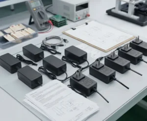
- External adapters (desktop or wall-mount). These keep mains voltage outside the device, which simplifies system-level certification. Best for portable diagnostic equipment and compact clinical instruments.
- Open-frame. Lowest cost and smallest footprint, but requires a protective system enclosure. Best for integrated equipment with controlled internal airflow — patient monitors, infusion pumps, and ventilators are common examples.
- Enclosed or U-chassis. Rugged and easy to mount, with fan or conduction cooling options. Best for high-power imaging systems, surgical displays, and lab analyzers.
- Board-mount AC-DC and isolated DC-DC converters. Used to create local patient-isolation barriers within a device — for example, an isolated analog sensor front end.
Class I vs. Class II. Class I relies on a protective earth connection. Class II uses reinforced double insulation and needs no earth pin, which eliminates the risk of a broken earth on mobile carts or in facilities with uncertain wiring. For most portable and home-healthcare-adjacent clinical devices, Class II is the cleaner option.
Key Criteria for Selecting a Medical Switching Power Supply
Safety and compliance must be resolved first. If a supply doesn’t meet the isolation or leakage requirements for your device class, no amount of performance headroom makes up for it.
Safety Standards and Certifications
At minimum, require:
- IEC 60601-1 Edition 3.2 (Edition 3.1 plus Amendment 2), with regional versions ES60601-1 and EN 60601-1.
- IEC 60601-1-2 Edition 4 for EMC, which raised immunity levels, including ±15 kV air discharge for electrostatic discharge (ESD).
- A CB report and valid certificates. A CB (Certification Body) report is the actual test record behind the certificate. “Designed to meet 60601-1” is a marketing claim, not evidence.
- Risk documentation compatible with your ISO 14971 risk management file.
Read the CB report, not just the certificate. It lists insulation ratings, test conditions, and any usage restrictions that apply to that specific model.
Isolation (MOPP vs. MOOP) and Leakage Current
A means of protection (MOP) is a layer of insulation or an equivalent safety measure. Means of Operator Protection (MOOP) protects clinical staff. Means of Patient Protection (MOPP) protects the patient and sets stricter thresholds.
Rating | Isolation Test | Creepage | Clearance |
|---|---|---|---|
2×MOOP | 3,000 VAC | ~5 mm | ~4 mm |
2×MOPP | 4,000 VAC | 8 mm | 5 mm |
Distances apply at a 250 V working voltage.
Applied parts — the parts of a device that contact the patient — come in three types: B (no conductive patient connection), BF (floating body contact), and CF (direct cardiac contact). Under normal conditions, patient leakage current limits are 100 µA for B and BF and 10 µA for CF.
When in doubt about the isolation level your device requires, choose 2×MOPP. The cost difference is small compared to a failed test or a mid-project redesign.
Power Specifications
- Headroom: Size the supply 20–30% above the worst-case continuous load. Check peak current separately for motors, pumps, and resistive heaters — they draw well above steady-state.
- Input range: Specify 90–264 VAC universal input so one SKU covers all major markets without hardware changes.
- Efficiency: Medical external supplies are often exempt from DoE Level VI and EU CoC Tier 2 requirements, but specifying those levels anyway is good engineering practice. Every efficiency point you gain is heat you don’t have to dissipate.
- Hold-up time: 10–20 ms is a reasonable target for riding through brief mains dips without triggering a system reset.
- Ripple and noise: Keep output ripple below roughly 1% of the nominal voltage. For ECG, ultrasound front ends, and precision sensor circuits, you may need a tighter spec — confirm with your analog design team.
Reliability and Lifetime
An MTBF (mean time between failures) number is only meaningful when the calculation method is stated. The same supply can produce a two- to three-fold difference between Telcordia SR-332 and MIL-HDBK-217F, especially at different ambient temperatures. Only compare MTBF figures calculated using the same method and reference temperature.
Electrolytic capacitors typically set the real service limit. Their life roughly halves for every 10 °C rise above rated temperature — 105 °C-rated parts are the minimum acceptable spec. Beyond the hardware, also confirm the supplier’s warranty length, planned product availability, and end-of-life (EOL) notice period. Medical devices commonly remain in production for 7–10 years.
Thermal Management and Size Constraints
Always read the derating curve before trusting the nameplate rating. Many supplies begin losing rated output above 50 °C ambient. A 300 W unit may deliver only 150–200 W at 70 °C, depending on the design.
- Convection cooling: Silent and maintenance-free, which suits patient care areas.
- Forced air: Higher power density per unit volume, but fans introduce acoustic noise, collect dust, and add a mechanical failure point — worth avoiding in clinical environments where quiet operation matters.
- Conduction-cooled baseplates: The right choice for sealed enclosures that require wipe-down or autoclave cleaning.
Also check the altitude rating. IEC 60601-1 assumes 2,000 m; if the equipment may be operated at altitude or transported by air, ask for a 5,000 m rating.
Application Fit
Different clinical environments impose different constraints, and specifying the supply without reference to the deployment context is a common source of late-stage compliance problems.
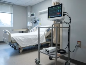
- Bedside and patient-connected equipment: Specify 2×MOPP isolation, BF or CF applied-part compatibility, and convection cooling for quiet operation.
- Portable and battery-backed systems: Match the supply’s output profile to the battery chemistry, and keep weight and footprint within what the mechanical design allows.
- High-power imaging systems and equipment carts: Use PFC for input compliance, an enclosed or U-chassis form factor for robustness, and confirm the availability of a 5 V or 12 V standby output for control logic.
For a broader view of how power supply selection maps to specific device categories and clinical environments, the Application section of this site covers power requirements across diagnostic, respiratory, and therapeutic device types in more detail.
Selection Checklist and Common Mistakes
Work through these steps in order — skipping early steps creates problems that surface in the final stages:
- Classify the device: applied part type (B, BF, or CF), Class I or II, and intended operating environment.
- Set the isolation level. Choose 2×MOPP when the classification is uncertain.
- Calculate the power budget with 20–30% headroom over worst-case continuous load.
- Select a form factor and cooling method based on the enclosure and environment.
- Verify certifications and read the full CB report, not just the cover page.
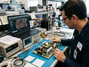
- Test leakage and EMC at the full-system level — with cables, connectors, and production shielding in place.
- Confirm long-term availability and the supplier’s EOL notification policy.
These are the mistakes that most often lead to failed approvals or project delays:
- Substituting an ITE-only supply. IEC 62368-1 certification does not substitute for IEC 60601-1.
- Treating 2×MOOP as sufficient for patient contact. It isn’t — MOOP protects operators, not patients.
- Ignoring the derating curve. The nameplate rating assumes specific ambient conditions that production environments often exceed.
- Assuming a certified supply guarantees a passing system EMC result. Cable routing, connector choice, and PCB layout all change the result.
- Comparing MTBF figures from different calculation methods. The numbers are not interchangeable.
Matching the Power Supply to Your Device
The right choice follows from what the device touches and how much power it draws:
- Patient-contact equipment: Use 2×MOPP isolation, Class II construction where the architecture allows, and leakage margins well inside the BF or CF limits — not right at the threshold.
- Equipment with no patient contact: 2×MOOP may be sufficient if your ISO 14971 risk assessment explicitly supports it and the applied-part classification is unambiguous.
- High-power systems and equipment carts: Use an enclosed supply with PFC, sized and cooled for the actual installation environment rather than ideal lab conditions.
Before you shortlist any supplier, request three documents: the CB test report, the full derating curve, and measured leakage current data at worst-case input. A supplier who can’t provide all three promptly is worth removing from consideration early.
If you need certified medical power supplies across the 5 W–500 W range — in desktop, open-frame, enclosed, and USB PD form factors — the Medical Power Supplies page includes a filterable product range, representative spec comparisons, and options for requesting samples and certification dossiers before any volume commitment.
Treat the power supply as a safety-critical component from the first schematic review — not as a procurement line item at the end of the design.
Frequently Asked Questions
Can I use an ITE power supply in a medical device?
Usually not. A power supply certified only to IEC 62368-1 is designed for ITE equipment, not for the tighter isolation and leakage current limits required by IEC 60601-1. If your device has any direct or indirect patient contact, using an ITE supply will usually create a compliance problem that appears during safety testing.
There are limited exceptions. A non-medical supply may be acceptable if it is located outside the patient environment or if the overall system provides the required protection elsewhere. In practice, though, that route often adds design complexity, documentation burden, and test risk. For most medical OEM projects, starting with a 60601-1 certified supply is the safer choice.
What is the difference between 2×MOPP and 2×MOOP?
The difference is who the protection is intended for. MOOP means Means of Operator Protection, while MOPP means Means of Patient Protection. Because patients are more vulnerable than operators, MOPP requirements are stricter.
In real selection work, 2×MOPP usually means stronger isolation, larger creepage and clearance distances, and tighter leakage current control than 2×MOOP. If your device includes any patient-contact function, 2×MOOP is not a substitute for 2×MOPP. When there is uncertainty, specifying 2×MOPP early is usually less costly than redesigning later.
Does a certified medical power supply guarantee that my device will pass EMC testing?
No. A certified medical power supply reduces risk, but it does not guarantee that the finished device will pass IEC 60601-1-2 EMC testing. EMC performance changes once the supply is installed in a real product with actual cables, shielding, connectors, PCB layout, motors, pumps, displays, and other noise sources.
This is why system-level EMC validation is essential. A supply that passes on its own can still fail in the final device because of cable routing, grounding strategy, enclosure structure, or noise coupling from nearby circuits. The right assumption is that certification helps, but final EMC performance must still be verified at the complete-system level.
What documents should I request before qualifying a medical power supply supplier?
Do not rely on the datasheet alone. At a minimum, ask for the CB test report, the certificate, the derating curve, and measured leakage current data. These documents tell you far more than a product page or marketing claim.
It is also good practice to request the EMC report, the MTBF calculation method, warranty terms, and the supplier’s end-of-life policy. If the supplier is experienced in medical OEM support, they should also be able to provide documentation that fits into your ISO 14971 risk management process. If these materials are missing early, problems usually appear later.
How much power headroom should I leave when selecting a medical power supply?
A practical rule is to size the power supply about 20–30% above the worst-case continuous load. That margin helps cover thermal derating, component aging, mains variation, and normal production tolerance. It also reduces the risk of running the supply too close to its limit during peak demand.
At the same time, bigger is not always better. Oversizing too far can waste space, increase cost, and reduce light-load efficiency. The goal is not to choose the largest model available, but to select a supply with enough margin for real operating conditions inside the actual enclosure.