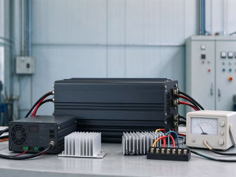
Factory power arrives as AC. Almost nothing inside a control cabinet runs on it. PLCs, sensors, HMIs, industrial PCs, and fieldbus gateways all need DC. The AC/DC converter sits between the grid and your electronics — and in an industrial system, it does far more than change current type. It determines how well your equipment handles surges, sags, heat, and noise.
When an industrial power supply fails, the cost is rarely just the replacement part. A dead 24VDC rail can halt a production line, take a trackside signal offline, or put a technician on the road to a remote substation. That reality shapes how these converters are designed, and how they should be specified. This guide walks through how they work, which specifications actually matter, what certification requirements apply by industry, and the spec mistakes behind most field failures.
What Is an AC/DC Converter?
An AC/DC converter takes AC from the facility supply and delivers regulated DC at the voltage your equipment needs. The operative word is “regulated.” The output must hold steady while input voltage, load current, and ambient temperature all shift around it.
The Core Function in Industrial Systems
Industrial AC/DC converters typically accept one of three input types:
- Single-phase 100–240VAC
- Three-phase 380–480VAC
- 400Hz AC, used on some airborne and military platforms
The output is a DC bus. In factory automation, that’s usually 24VDC. Telecom and network equipment runs on 48VDC or -48VDC. Auxiliary logic and sensors often use 5V or 12V rails. AC dominates transmission because transformers make it easy to step voltage up and down. Electronic circuits need stable DC, and the converter bridges that gap.
The 24VDC bus matters more than most engineers give it credit for. It feeds every PLC input card, proximity sensor, safety relay, and solenoid valve in the cabinet. When that bus sags under a motor start or picks up switching noise, the symptoms show up as unexplained I/O faults, sensor dropouts, and trips that take hours to trace. Treat the power supply as a system-level decision, not an afterthought on the BOM.
AC/DC Converter vs. Power Supply vs. Rectifier: Clearing Up the Terms
These terms appear interchangeably in datasheets and purchase orders, but they don’t mean the same thing. A rectifier is one stage inside a converter. “Converter” and “power supply” often describe the same product but hint at different form factors.
Term | Functional scope | Typical industrial form |
|---|---|---|
Rectifier | Converts AC to unregulated, pulsating DC. No voltage regulation. | Diode bridge inside a supply or drive |
AC/DC converter | Rectifies, regulates, and usually isolates. | PCB-mount module, open-frame board |
AC/DC power supply | A complete converter with housing, terminals, and protections. | DIN-rail unit, enclosed or rack-mount supply |
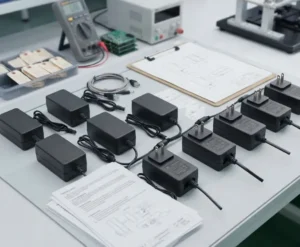
External adapters are a consumer category. They rarely carry industrial certifications and are seldom appropriate for cabinet installation.
How Does an Industrial AC/DC Converter Work?
A modern industrial converter moves power through five stages:
Input filter → Rectifier → PFC → Isolated DC/DC stage → Output filter and regulation
Each stage connects to a specific reliability or compliance outcome. Understanding what happens at each step makes datasheets far easier to read.
Input Stage: EMI Filtering, Inrush Limiting, and Surge Protection
The input stage protects the converter from the grid and protects the grid from the converter. An EMI filter prevents high-frequency switching noise from traveling back into the supply lines — this is what allows a unit to meet conducted emission limits under EN 55011, EN 55032, or the industrial emission standard IEC 61000-6-4. Surge protection, usually metal oxide varistors (MOVs), absorbs high-energy transients from lightning strikes or large inductive loads switching off, as defined in IEC 61000-4-5.
Inrush current limiting is frequently overlooked. When bulk capacitors charge at power-up, they can pull tens of amps for a few milliseconds. Many supplies use an NTC thermistor to limit this. The problem: an NTC only works cold. After a brief power interruption, the thermistor is still warm and offers little resistance, so the inrush can spike much higher than expected. Active inrush limiting circuits don’t have this weakness.
Caution: Inrush currents add up fast. Five supplies on one breaker, all powered on simultaneously, can trip a breaker that handles their combined steady-state load without issue. Check the per-unit inrush rating and either stagger startup or select appropriate breaker trip curves.
Power Factor Correction (PFC)
Without PFC, a converter draws current in short, sharp pulses at the peak of each AC cycle. This distorts the waveform and injects harmonics into the facility supply. IEC 61000-3-2 sets harmonic current limits for equipment drawing more than 75W of input power, so active PFC is effectively mandatory for most industrial supplies.
Active PFC typically raises the power factor to 0.95 or above, with better designs reaching 0.98–0.99. The benefit extends beyond compliance. A cabinet with many non-PFC supplies accumulates harmonic current in the neutral conductor and heats upstream transformers. Active PFC removes that hidden load from your distribution system — and usually enables a wide universal input range as a side effect.
Switching Conversion and Galvanic Isolation
After PFC, the converter has a high-voltage DC bus, typically 380–400VDC. Power transistors switch this at high frequency using PWM (pulse width modulation) control, and a high-frequency transformer steps it down. Topology follows power level:
- Flyback: low power, typically up to around 150W
- Forward: mid power, roughly 100–500W
- LLC resonant or phase-shifted full bridge: higher power, where soft switching maintains efficiency
The transformer also provides galvanic isolation — no direct conductive path between the mains and the DC output. Industrial supplies commonly rate input-to-output isolation at 3000VAC. Medical-grade designs often reach 4000VAC. This rating determines whether the output can safely connect to operator-accessible interfaces, communication ports, or safety circuits. The isolation barrier is what makes the low-voltage side safe to work on.
Output Stage: Rectification, Filtering, and Regulation
The transformer output is rectified a second time, increasingly using synchronous rectification — MOSFETs rather than diodes — to recover efficiency at low output voltages. LC filters smooth the waveform. A feedback loop compares the output to a reference and adjusts PWM duty cycle continuously to hold voltage steady under changing load.
Three datasheet numbers define output quality:
- Ripple and noise: typically 50–150mVp-p for industrial units, measured at 20MHz bandwidth
- Load regulation: voltage shift from no load to full load
- Line regulation: voltage shift across the full input range
If the supply feeds analog acquisition cards, 4–20mA loops, or precision measurement circuits, ripple and noise matter more than rated wattage. A 480W supply with 150mV of ripple can underperform a 240W unit with 50mV in that context.
Linear vs. Switching AC/DC Converters: Which Fits Industrial Use?
Switching converters dominate industrial work, and for practical reasons. They typically reach 85–95% efficiency and deliver several times the power density of linear designs. A linear supply uses a 50/60Hz transformer followed by a series regulator that burns off excess voltage as heat — efficiency sits between 40% and 60%.
Linear supplies still have a narrow role. Their output noise floor is extremely low, with no switching-frequency interference. That matters for some laboratory instruments, low-level sensor front ends, and precision analog circuits. Outside those cases, their size, weight, and thermal output are hard to justify in a cabinet.
Criterion | Switching converter | Linear converter |
|---|---|---|
Efficiency | Typically 85–95% | Typically 40–60% |
Size / power density | Compact, high density | Large, heavy transformer |
Output noise | Low, with switching residue | Very low |
Heat generation | Low | High |
Input range | Wide (e.g., 85–264VAC) | Narrow, often requires tap selection |
Typical industrial use | Control cabinets, telecom, automation, rugged systems | Lab instruments, sensitive analog stages |
Default to switching. Cabinet space and cooling headroom are almost always limited. For noise-sensitive circuits, the more practical solution is a switching supply on the main bus with a local LDO regulator at the sensitive load — cleaner output without the thermal penalty.
Common Industrial AC/DC Converter Form Factors
Mounting format affects cooling, serviceability, certification scope, and total installed cost. The right choice comes down to where the converter lives and who is responsible for the enclosure around it.
Form factor | Typical power range | Cooling | Typical application | Selection note |
|---|---|---|---|---|
DIN-rail | 30W–1kW | Convection | Control cabinets, automation | Look for DC-OK relay contacts and redundancy support |
Enclosed / panel-mount | 50W–3kW | Convection or fan | Machine-integrated equipment | Check fan life and airflow direction |
Open-frame | 15W–500W | Convection or system airflow | Cost-sensitive OEM equipment | You provide the safety enclosure and thermal design |
PCB-mount / encapsulated | 1W–150W | Conduction through board | Board-level auxiliary power | Potting improves resistance to vibration and humidity |
Rack-mount / front-end | 500W–several kW | Forced air | Telecom, data, test systems | Hot-swap capability, N+1 redundancy, digital monitoring |
Conduction-cooled / rugged | 50W–1.5kW | Baseplate to cold wall | Military, outdoor, sealed enclosures | Requires a properly designed thermal interface |
Open-frame units look cheaper on the BOM but shift significant work onto you. Creepage clearances, the safety enclosure, and thermal validation all become your responsibility. For low-volume builds, a DIN-rail or enclosed supply often costs less once you account for that engineering time.
Key Specifications to Evaluate Before You Buy
Most datasheets list 30 or more parameters. A smaller group determines whether the converter actually survives your installation. Here is what to focus on.
Input Range and Grid Conditions
Universal-input supplies accept 85–264VAC at 47–63Hz. Three-phase units typically cover 340–575VAC, and some also accept DC input for battery backup topologies. Some airborne and military platforms supply 400Hz AC, which requires a supply specifically rated for it.
The nominal range tells only part of the story. Semiconductor fabs often need compliance with SEMI F47, which defines voltage sag immunity — typically riding through a drop to 50% of nominal for 200ms. Sites running on generators, weak rural grids, or lines with heavy motor loads should use wide-input models. Also check how the unit behaves during brownouts. A clean shutdown and restart is acceptable. Oscillating repeatedly near the undervoltage threshold is not.
Output Voltage, Current, and Peak Load Capability
Rated power is what the supply delivers continuously. Peak power — often called “power boost” — is what it can handle briefly, usually 120–150% of rating for a few seconds. Motors, solenoid valves, contactor coils, and large capacitive loads all draw well above their running current at startup. A supply without peak capability may enter overload protection every time the machine starts.
Target 60–80% of the supply’s rating as your continuous load. That margin handles startup peaks, leaves room for future expansion, and directly reduces internal temperature — which extends component life. Adjustable output voltage, typically ±10%, lets you compensate for voltage drop on long cable runs to field devices.
Efficiency, Thermal Derating, and Operating Temperature
Efficiency determines how much heat ends up in your cabinet. Take a 480W load. At 84% efficiency, the supply draws about 571W and dissipates around 91W as heat. At 94%, it draws about 511W and dissipates around 31W. That 10-point difference adds roughly 60W of heat — which may determine whether you need a cabinet fan or a cooling unit.
Every industrial supply has a derating curve. Most deliver full power up to 50–60°C ambient, then derate linearly — often reaching 50% of rated output at 70°C. Altitude above 2000m also requires derating, since thinner air transfers less heat. Convection-cooled supplies also need the clearance above and below that the datasheet specifies; block that airflow and you’ve changed the thermal design.
Apply the derating curve to the air temperature at the supply, not the room temperature. A 35°C factory floor can produce 55°C air near the top of a cabinet loaded with drives and transformers. Measure or estimate that temperature before sizing your supply.
Safety, EMC, and Industry Certifications
Certifications aren’t bureaucratic overhead. A supply certified to the wrong standard can force recertification of your entire end product, adding months to a schedule. Start with the standard governing your end equipment, then confirm the supply aligns with it.
Insulation class is also worth understanding. Class I equipment relies on protective earth for safety. Class II uses double or reinforced insulation and doesn’t depend on earth — useful where a reliable protective earth can’t be guaranteed, such as in some outdoor or mobile installations.
Industry | Key standards | Main concern |
|---|---|---|
Industrial control | UL 61010-2-201, IEC 61000-6-2 / 6-4 | Safety of control equipment, industrial EMC |
ICT and general equipment | IEC/UL 62368-1, EN 55032 | Hazard-based safety, emissions |
Medical | IEC 60601-1 (2×MOPP), IEC 60601-1-2 | Patient protection, low leakage current, EMC |
Railway | EN 50121 series | Rail EMC environment |
Military / aerospace | MIL-STD-461, MIL-STD-810, MIL-STD-704 | EMI, environmental stress, aircraft power quality |
Harmonics (all sectors) | IEC 61000-3-2 | Input current harmonics |
For medical equipment, the requirements are substantially more stringent — 2×MOPP isolation and leakage current limits below 100µA are non-negotiable starting points. If you’re specifying power for patient-connected devices, the medical power supply selection criteria are covered separately in a dedicated guide.
Reliability, Protection, and Hold-Up Time
MTBF figures are among the most misused numbers in power supply marketing. One vendor calculates under Telcordia SR-332 at 25°C; another uses MIL-HDBK-217F at 40°C. Those numbers aren’t comparable. Always ask for the method, temperature assumption, and load condition. And remember: MTBF is a statistical failure rate, not a service life figure.
Actual service life is usually limited by electrolytic capacitors. Their life roughly doubles for every 10°C drop in operating temperature. Running a supply 20°C cooler can extend its life by a factor of four. Derating and airflow are the most cost-effective reliability upgrades available.
Protection behavior matters as much as the presence of protection features. Almost every industrial supply includes OVP, OCP, OTP, and short-circuit protection, but overload response differs:
- Hiccup mode: the supply shuts down and retries repeatedly. It protects the supply but may never successfully start a large capacitive load.
- Constant current mode: the supply limits current and lets output voltage sag until the load charges. This is better for capacitive loads and motor drives.
Hold-up time — typically 10–20ms at full load — is how long the output stays in regulation after input power disappears. It bridges brief grid interruptions and transfer switching. For equipment where any dropout triggers a costly reset sequence, look for extended hold-up or add a downstream DC UPS module.
AC/DC Converters Across Industrial Applications
Specifications only make sense in context. The same 24VDC, 10A supply may be a solid choice in one installation and entirely wrong in another.
Factory Automation and Control Cabinets
The 24VDC bus in a typical automation cabinet feeds PLCs, HMIs, remote I/O, sensors, safety relays, and servo drive control electronics. Because downtime carries real cost, redundancy is common. A 1+1 configuration runs two supplies through a redundancy module, either one able to carry the full load. The DC-OK relay contact on each supply should wire to a PLC input, so maintenance staff know when a unit has failed before the backup fails too.
Selective branch protection is the other upgrade most cabinets need. A short on one sensor branch shouldn’t collapse the entire bus. Electronic circuit breakers (e-fuses) isolate a faulty branch in milliseconds without affecting the rest of the system. Standard thermal breakers often can’t trip on the limited fault current a 24V supply delivers.
Communication and Network Equipment
Telecom and data infrastructure runs on 48VDC or -48VDC buses, usually float-charged against battery strings. Rack-mount front-end supplies operate in N+1 configurations — one extra module covers any single failure — and hot-swap capability means a failed unit comes out without powering down the rack. PMBus digital monitoring surfaces voltage, current, temperature, and fault status to the management system. At remote sites, that telemetry supports predictive maintenance rather than reactive emergency visits.
Energy, Transportation, and Rugged Environments
Substations and battery energy storage systems use AC/DC converters for protection relay power, measurement units, and BMS electronics. High isolation, wide operating temperature, and strong surge immunity are table stakes here, since protection switching generates severe transients on the same bus. Rail trackside equipment adds EN 50121 EMC compliance and vibration resistance. Outdoor cabinets may swing from -40°C winters to summer solar loading on the enclosure.
Military and other platform-specific applications follow a simple rule: match the converter to the platform bus. Aircraft with 115VAC 400Hz power need a 400Hz-rated supply compliant with MIL-STD-704. Sealed enclosures call for conduction-cooled designs that transfer heat through the baseplate to a cold wall. Conformal coating handles humidity, salt fog, and dust. In these environments, the thermal path and mechanical design often carry as much weight as the electrical specification.
For a broader view of how power supply requirements vary by application sector — from industrial automation to medical and networking — the application overview covers the key differences across each category.
How to Choose the Right AC/DC Converter: A Step-by-Step Checklist
Order matters during specification. Each step narrows the field for the next, and jumping ahead to brand or price usually means revisiting earlier decisions. Use this sequence when preparing a request for quotation.
- Define the input. Record voltage, phase count, frequency, and grid quality — including sags, generator supply, and expected transients.
- Calculate the load. Separate continuous power, peak power, and startup behavior for motors, valves, and capacitive loads.
- Set derating margin. Size the supply based on cabinet internal temperature, altitude, and a continuous load target of 60–80% of rating.
- Determine isolation and safety class. Identify target markets, the governing industry standard, and whether Class I or Class II insulation applies.
- Confirm EMC requirements. Match the supply to IEC 61000-6-2/6-4 or the relevant sector standard, such as EN 50121 or MIL-STD-461.
- Choose form factor and cooling method. Base this on available space, airflow constraints, and who owns the enclosure.
- Specify redundancy and monitoring. Decide between 1+1 and N+1, and whether DC-OK signals or PMBus monitoring are needed.
- Evaluate the supplier. Ask for certification files, MTBF calculation methodology, long-term availability commitments, and customization capability.
Common Mistakes When Specifying Industrial AC/DC Converters
Most power supply field failures don’t trace back to defective units. They trace back to specification errors made months before installation. These five come up most often.
1. Sizing only for rated load. Ignoring peak and capacitive startup loads causes failed startups or endless hiccup cycling. Account for motor and valve inrush, downstream capacitance, and choose a supply with peak capability or constant current overload behavior.
2. Using room temperature instead of cabinet temperature. The supply runs past its derating curve, electrolytic capacitors age prematurely, and failures show up 18 months later — long after anyone connects them to a thermal problem.
3. Sharing a breaker without checking inrush. Multiple supplies powering up together can trip a breaker that handles steady-state load easily. Add up per-unit inrush ratings, stagger startup where possible, or select appropriate trip curves.
4. Ignoring EMI filter leakage current. Each Y-capacitor in an input filter leaks a small current to earth — often 0.5–1mA per supply. Ten supplies behind a single 30mA RCD can cause repeated nuisance tripping. Check leakage values and distribute loads across protection devices.
5. Treating MTBF as service life. A 500,000-hour MTBF figure doesn’t mean 57 years of operation. Confirm the calculation standard and temperature condition, and estimate actual service life from capacitor operating temperature instead.
Several of these issues only surface under real site conditions — unusual grid behavior, dense cabinets, or mixed load types. A short review with an applications engineer at the specification stage typically costs far less than a field service call.
Frequently Asked Questions
What is the difference between an AC/DC converter and a DC/DC converter?
The input source is the difference. An AC/DC converter takes power from the AC grid or an AC platform bus and produces regulated DC. A DC/DC converter takes an existing DC source and changes it to another DC voltage. DC/DC converters are common on battery-powered or DC-bus platforms such as 24V vehicle systems, 28V military buses, or 48V telecom infrastructure.
Why is 24VDC the standard in industrial automation?
24VDC falls within SELV limits, making it safe for technicians to work near without special insulation precautions. IEC 61131-2 defines 24VDC supply ranges for PLC systems, and the ecosystem of sensors, relays, and I/O modules built around this voltage is comprehensive. Cable losses remain acceptable over typical cabinet and field wiring distances.
How long does an industrial AC/DC power supply last?
Service life depends mainly on electrolytic capacitor temperature, which is a function of load and thermal design. A well-derated supply in a cool cabinet can run reliably for 10 years or more. The same supply running hot at full load may fail in a fraction of that time. Manufacturers typically state life in operating hours at a specified temperature and load — always check those conditions before comparing models.
Can I connect two AC/DC power supplies in parallel?
Only if the manufacturer explicitly supports parallel operation or current sharing. Otherwise, one supply ends up carrying most of the load while the other barely contributes. For redundancy, use ORing diodes or a dedicated redundancy module — this prevents a failed supply from pulling down the shared bus.
Getting the Power Supply Decision Right
Specifying an AC/DC converter is a system-level decision. The right unit depends on your input source, load profile, thermal environment, and the certification requirements of your end product. Getting those four factors right turns the power supply into one of the most reliable parts of your system.
If you’re evaluating suppliers or working through a custom requirement — a non-standard output voltage, specific certifications for your target markets, or a form factor that isn’t available off the shelf — Quankang’s engineering team supports selection reviews, custom development, and pre-production sample evaluation. Browse the full AC/DC power supply range to see standard models, or get in touch to discuss your specific requirements.