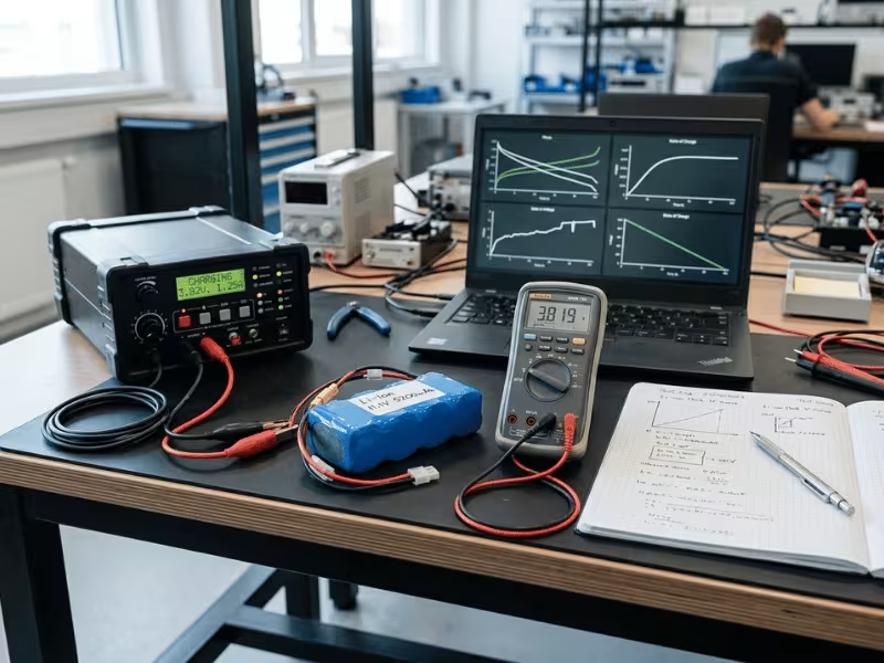
Charging an instant power battery charger can take anywhere from 30 minutes to more than 10 hours. The exact number depends on battery capacity, charge current, cell chemistry, and how full the battery needs to be before it returns to duty. For a small 10 Ah lithium pack charged at around 0.5C, the bulk estimate lands near 2 hours, though the real time to full charge often runs longer once tapering and system losses are included. A large industrial pack on a conservative charge profile can run most of a shift and beyond.
First, a quick clarification. The phrase “instant power battery charger” gets used loosely across suppliers and applications. In B2B contexts it may describe a portable backup power system, a quick-turnaround charger for battery-powered equipment, or an emergency power unit designed to get a device operational fast. Because the label varies, charging time is best judged by the underlying specs — battery capacity, chemistry, charger output current, and charge profile — rather than the name on the box. That is the frame this guide uses.
This article gives you the number and, more usefully, shows you how to calculate it for your own system. Here’s what you’ll learn:
- A quick-reference table of realistic charge times across common B2B applications
- The battery charging time formula engineers use, plus why real time runs longer
- How charger current affects charging time, and how chemistry sets the ceiling
- A four-step method to estimate charge time for any pack
Quankang designs AC-DC adapters and battery chargers on an OEM/ODM basis, so the framing here reflects how charge time actually gets engineered into a product, not assumed.
Quick Answer: Charge Time at a Glance
Full-charge time roughly equals battery capacity divided by charge current, then padded for the constant-voltage taper and conversion losses. That single relationship explains why a portable diagnostic device tops up in an hour while a backup power module may need the better part of a workday.
The table below shows representative outcomes across common applications. Treat these as defensible bands, not exact figures, since your real number shifts with chemistry and charger rating.
Application example | Battery capacity | Charge current / C-rate | Approx. full-charge time |
|---|---|---|---|
Portable diagnostic device | 2–4 Ah (Li-ion) | 0.5–1C | 1–2 hours |
Battery-powered cleaning machine | 20–40 Ah (lead-acid) | 0.15–0.25C | 6–10 hours |
AGV / AMR pack | 30–60 Ah (LiFePO4) | 0.5–1C | 1–2.5 hours |
Compact backup power module | 50–100 Ah (lead-acid / LiFePO4) | 0.1–0.3C | 4–10 hours |
Charge time is not linear. Because current tapers during the final stage, the last stretch of a charge can take disproportionately longer than the bulk phase. Plan your uptime around usable charge, not just the full-charge figure.
The Battery Charging Time Formula
Start with the base equation, then adjust for real-world losses. The clean estimate is straightforward:
Charge time (hours) ≈ Battery capacity (Ah) ÷ Charge current (A)
C-rate is the shorthand that ties current to capacity. A 1C rate charges the full capacity in one hour, 0.5C in two hours, and 2C in half an hour. So a 20 Ah pack charged at 0.5C draws 10 A and fills in about two hours on paper.
Real charge time typically runs 15–40% longer than the formula suggests. The constant-voltage taper at the top of the cycle slows current acceptance, and every charger loses some energy to conversion inefficiency and heat. Build that overhead into your duty-cycle planning so you don’t spec a charger that hits its rated current but still misses your turnaround target.
Worked example: A 40 Ah LiFePO4 pack charged at 20 A (0.5C) calculates to 2 hours. Add roughly 30% for taper and losses, and your realistic full-charge time lands near 2.5–2.6 hours. Spec the charger current to the real number, not the theoretical one.
Estimate Your Charge Time in Four Steps
You can size a realistic figure for almost any pack with a short, repeatable process:
- Confirm battery capacity in Ah (or convert Wh to Ah using the pack voltage).
- Confirm the maximum accepted charge current — the lower of what the cell chemistry safely allows and what your charger delivers.
- Identify the chemistry and charge profile (lithium, LiFePO4, or lead-acid), since each tapers differently near full.
- Add taper and efficiency overhead — a 15–40% buffer on top of the base calculation gets you a number you can defend on a spec sheet.
Why Full Charge Time Isn’t Linear: CC/CV Stages
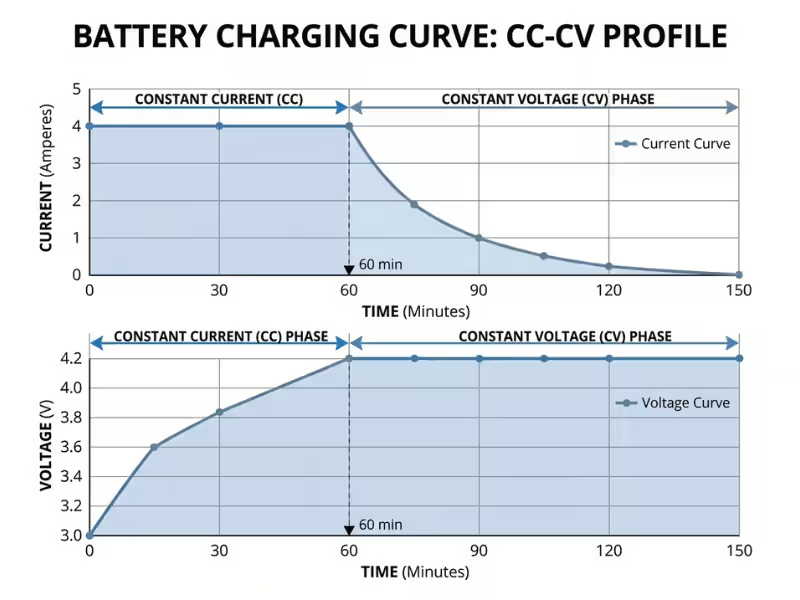
The reason the last stretch drags is the two-stage CC/CV charge profile that most modern chemistries use. Understanding these stages tells you where your time goes.
Constant current (CC) — the bulk stage: The charger pushes maximum rated current until the cell reaches its voltage limit. This stage does the heavy lifting, typically taking a pack from empty to roughly 70–80% state-of-charge in the shortest time.
Constant voltage (CV) — the taper stage: Once the voltage ceiling is hit, current tapers down while voltage holds steady. Charging the final 20–30% this way can account for a substantial share of total charge time, because the cell accepts progressively less current.
The purchasing insight is direct: if your application only needs the battery back to 80% before its next duty cycle, you can skip most of the CV taper and cut effective recharge time significantly. Sizing your charge target to state-of-charge, rather than always chasing 100%, is one of the cheapest ways to improve uptime.
The Key Variables That Affect Charging Time
Four variables decide whether your charge takes 30 minutes or 10 hours: battery capacity and chemistry, charger output, protocol compatibility, and temperature. Each carries a takeaway you can apply directly to a spec sheet.
Battery Capacity and Chemistry
Capacity sets the volume of energy to move, but chemistry sets the ceiling on how fast you can safely move it. A faster charger cannot override the cell’s chemistry limit without risking safety and cycle life. This is why lithium battery charging time and lead-acid battery charging time differ so much even at similar capacities.
Typical safe continuous charge-rate ceilings:
- Li-ion: Commonly 0.5–1C, with some cells rated higher for fast-charge duty
- LiFePO4: Often 0.5–1C, valued for tolerance of higher rates and long cycle life
- Lead-acid: Usually 0.1–0.3C, which is why cleaning machines and backup units charge slowly
Engineering takeaway: Confirm the cell’s maximum continuous charge current before selecting charger output. Match the charger to the chemistry ceiling, not the other way around.
Charger Output Power and Charge Current
The charger’s rated output current and power set the floor on how fast you can charge. This is the heart of how charger current affects charging time: whichever ceiling is lower — the battery’s safe charge rate or the charger’s rated output — determines your real time.
For example, if a pack can safely accept 20 A but your charger only delivers 10 A, you charge at 10 A regardless of what the battery allows. Conversely, an oversized charger delivers no benefit once you hit the cell’s limit.
Selection note: The slower of charger-max and battery-max sets your real charge time. Spec both together, and size the charger’s continuous output to the current you actually need — with thermal headroom, not just peak rating.
Charging Protocol and Compatibility
In battery systems that rely on BMS communication or charger-pack signaling, the charger and battery management system have to agree before current flows at the intended rate. A compatibility mismatch can reduce charging performance or prevent normal charging behavior.
Run this compatibility check before committing to a charger:
- Voltage window: Charger output voltage matches the pack’s charge voltage and cell count
- Connector and protocol: Physical connector and communication protocol align with the BMS
- BMS communication: Charger can read the BMS state and adjust current, if the pack requires it
Design implication: For any pack with a smart BMS, verify protocol compatibility early. A perfectly rated charger delivers zero benefit if it can’t negotiate the handshake.
Temperature, Efficiency, and Heat
Ambient temperature and thermal management move both your charge time and your battery’s lifespan. Cold slows charge acceptance, heat forces the charger or BMS to derate current, and efficiency losses stretch real time beyond the formula.
Charging in cold conditions can extend time noticeably, since many chemistries restrict charge current below certain temperatures to protect the cells. High temperatures trigger derating that quietly lowers delivered current mid-charge.
Practical implication: Faster charging generates more heat, and sustained heat shortens cycle life. If your application runs high duty cycles, a moderately slower charge profile with strong thermal management often delivers lower total cost of ownership than the fastest possible charge.
Full-Charge Time vs. Usable Recharge Time
The most useful number for uptime is often not full-charge time — it’s the time to reach a usable state-of-charge that lets the equipment resume duty. Distinguishing the two changes how you spec and schedule charging.
Full-charge strategy: Charge to 100% during long idle windows, such as overnight or between shifts. Best when the equipment sits unused for hours and you want maximum runtime per cycle.
Opportunity charging: Top up to a usable state-of-charge during short breaks, then return to duty. Best for high-utilization equipment where full recharge windows don’t exist.
Consider an AGV that runs continuous shifts. Rather than pulling it offline for a two-hour full charge, you top it up during a scheduled break — reaching enough state-of-charge to finish the shift, then completing a full or balancing charge overnight. This cycle-based approach keeps fleet uptime high without oversizing the charger.
Engineering takeaway: Define your target state-of-charge per duty cycle first. That number, not the full-charge figure, tells you the charger current you actually need.
Charge Time Expectations by Application
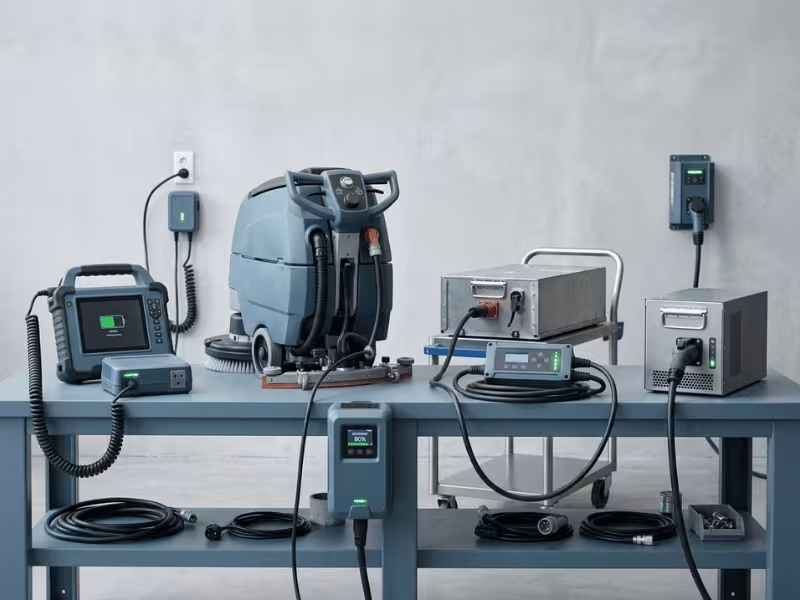
Realistic charge-time targets shift with each application’s priorities — speed, longevity, or safety. The table below maps common B2B use cases to a practical strategy and time expectation.
Application | Typical priority | Charge strategy | Practical time expectation |
|---|---|---|---|
Portable diagnostic device | Safety + certification | Full charge between uses | 1–2 hours |
Field service power unit | Uptime + portability | Opportunity + overnight full | 2–6 hours full |
Battery-powered cleaning machine | Cost + cycle life | Overnight full charge | 6–10 hours |
AGV / AMR pack | Maximum uptime | Opportunity charging | 15–45 min top-up; full overnight |
Compact backup power module | Readiness + longevity | Slow float / full charge | 4–10 hours |
For portable diagnostic and monitoring devices, charge time sits behind safety and certification — the charger must meet medical-grade standards even if that means a more conservative profile. If you’re specifying power for regulated equipment, our medical power supplies are built around those compliance-first requirements. For AGVs and robotics, uptime dominates, so opportunity charging and fast partial top-ups matter more than the full-charge number.
Selection note: Let the application’s priority drive the charge strategy, then reverse-engineer the charger rating from there. Speed, longevity, and safety pull in different directions, so decide which one leads.

How to Choose a Charger for Your Target Charge Time
Choose the charger by working backward from your target charge time, then balancing it against efficiency, safety, and battery life. Run through this selection checklist before you commit to a supplier:
- Voltage and current spec: Match output voltage to the pack, and size continuous output current to your real target time — including CV taper and loss overhead
- BMS and protocol match: Confirm the charger negotiates correctly with the pack’s BMS and communication protocol
- Efficiency rating: Higher efficiency means less wasted energy, lower heat, and more consistent charge time
- Thermal management: Ensure the charger holds rated output without derating across your operating temperature range
- Certifications: Verify the required standards — IEC, UL, CE, and medical-grade certification where the application demands it
Weigh the trade-offs deliberately. The fastest charger is rarely the best choice once heat, cycle life, and certification cost enter the calculation. When an off-the-shelf unit can’t hit your voltage, chemistry, and turnaround targets together, a custom power adapter matched to your BMS, protocol, and certification requirements keeps the specified charge time intact in production.
Design implication: Document your target state-of-charge, duty cycle, and certification needs before requesting quotes. A clear brief gets you a charger that hits the number, not a generic unit that misses it.
Frequently Asked Questions
Can a higher-current charger always reduce charge time?
No. A charger can only charge as fast as the battery safely accepts. If your pack’s chemistry ceiling is 0.5C, a charger rated well above that current charges no faster — it just adds cost and heat. The lower of the two limits always wins.
Why does charging slow down near full capacity?
Because most chemistries switch from constant current to constant voltage near the top of the cycle. During that CV taper, current drops steadily while voltage holds, so the final portion of the charge takes proportionally longer than the bulk stage.
Does fast charging shorten battery life?
It can. Higher charge currents raise cell temperature, and sustained heat accelerates wear over many cycles. For high-duty applications, a moderately slower profile with good thermal management often delivers better total cost of ownership than maximum speed.
How do I estimate charging time for a custom pack?
Divide capacity (Ah) by your chosen charge current (A) for a baseline, then add a 15–40% buffer for the CV taper and efficiency losses. Confirm the chemistry’s safe charge rate before locking in the current.
Is a full 100% charge always necessary in industrial applications?
Rarely. Many operations run better on opportunity charging to a usable state-of-charge that covers the next duty cycle, with a full or balancing charge scheduled during long idle windows. Charging only to what you need cuts downtime and can extend cycle life.
Getting the Charge Time Your System Actually Needs
Charge time is engineered, not assumed. Once you know your battery capacity, safe charge current, chemistry ceiling, and the state-of-charge your duty cycle actually requires, you can calculate a realistic number and spec a charger that delivers it. The formula gets you close; the CC/CV taper, protocol compatibility, and thermal headroom get you to a figure you can stand behind.
The applications differ, but the discipline is the same: define the target, respect the chemistry ceiling, and balance speed against safety and cycle life. To spec a charger matched to your system, share your pack voltage, battery capacity, target turnaround time, and certification needs — and the Quankang team can turn that brief into an OEM/ODM proposal. Explore the full product range to see where a tailored charger or adapter fits your application.