MTBF (Mean Time Between Failures) estimates the average failure rate across a population of units during their stable operating period. Lifetime estimates how long a single unit can operate before wear-out mechanisms—primarily capacitor aging—end its service. They measure different failure phases, rely on different calculations, and answer different engineering questions. Confusing the two when comparing vendor datasheets leads to one of the most common and costly mistakes in power supply selection.
This guide explains what each metric actually measures, how each is calculated, and how to use both together when evaluating power supply reliability across vendors. If you’ve ever wondered why a high MTBF doesn’t guarantee a long service life, this is the article that answers that.
What Is MTBF in a Power Supply?
MTBF—Mean Time Between Failures—is a statistical measure of how frequently a population of units fails during normal operation, expressed in hours. It is not a prediction of how long any individual unit will run before it breaks.
The core relationship is:
MTBF = 1 / λ
Where λ is the failure rate per unit time. A power supply with an MTBF of 1,000,000 hours (approximately 114 years) has a failure rate of roughly 0.88% per year. In practical terms: out of 1,000 units in service, approximately 8–9 can be expected to fail per year under rated conditions.
That number describes the statistical behavior of a fleet—not the service life of any individual unit.
How MTBF Is Calculated
Reliability engineers use established standards to calculate MTBF. The two most widely applied in commercial and industrial power supply design are:
- MIL-HDBK-217F — A U.S. Department of Defense standard with two methods: Parts Count Reliability Prediction (used during early design phases) and Part Stress Analysis Prediction (applied in later design phases). The stress analysis method sums each component’s failure rate, factoring in ambient temperature, electrical stress, base failure rate, power rating, operating environment, and part quality.
- Telcordia SR-332 (formerly Bellcore) — Widely used in telecommunications applications. It uses a different component failure-rate database and different environmental models than MIL-HDBK-217F.
This distinction matters immediately: two MTBF figures calculated to different standards are not directly comparable. More on that below.
The Bathtub Curve: Where MTBF Fits
Power supply failure rates over time follow a characteristic bathtub-shaped curve with three distinct stages:
- Early failure period — Elevated failure rate at the start of product life, typically caused by latent manufacturing defects not caught during inspection. Reputable manufacturers eliminate this through 100% final inspection and burn-in testing before shipment.
- Stable (useful life) period — Failure rate drops to a low, roughly constant level. This is the region MTBF describes.
- Wear-out period — Failure rate accelerates as materials age and degrade. Electrolytic capacitors are typically the first components to reach this stage.
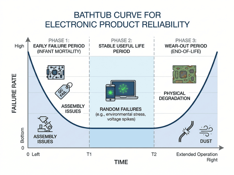
This distinction is critical: MTBF is a useful-life metric. It does not describe what happens when components begin to wear out.
What Is Lifetime in a Power Supply?
Lifetime—sometimes called service life or operational life—estimates how long a specific unit can operate before wear-out mechanisms cause it to fail or degrade beyond acceptable limits. Where MTBF describes the flat middle section of the bathtub curve, lifetime describes when that curve starts rising on the right.
The Capacitor Is Usually the Weakest Link
In most AC-DC power supplies, the component that most commonly limits lifetime is the aluminum electrolytic capacitor. Its liquid electrolyte gradually evaporates through the capacitor’s seals over time. As the electrolyte depletes, capacitance drops and equivalent series resistance (ESR) rises—until the capacitor can no longer perform its function.
Because the capacitor ages fastest, estimating its remaining life effectively estimates the whole power supply’s lifetime.
How Lifetime Is Calculated
Capacitor manufacturers specify a rated lifetime at a defined maximum temperature (typically 85°C or 105°C). From that baseline, lifetime at any other operating temperature is estimated using Arrhenius-based formulas.
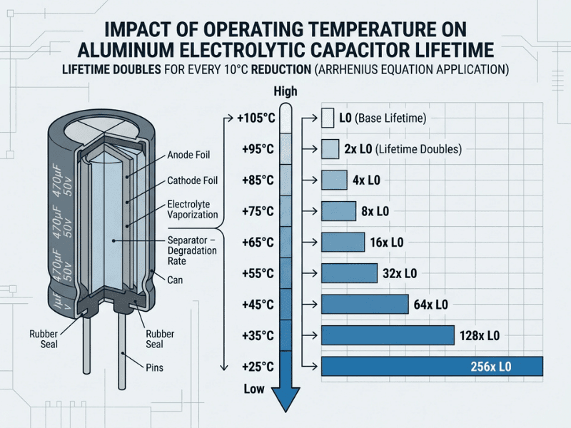
For liquid (wet) electrolytic capacitors, lifetime roughly doubles for every 10°C reduction in operating temperature:
L = L₀ × 2^((T₀ − T) / 10)
Where L is estimated lifetime at operating temperature T, and L₀ is the rated lifetime at rated temperature T₀.
For polymer electrolytic capacitors, the temperature sensitivity is lower—lifetime increases approximately tenfold for every 20°C reduction in component temperature.
A worked example: A capacitor rated for 2,000 hours at 105°C, operating at 65°C, has an estimated lifetime of 2,000 × 2⁴ = 32,000 hours—approximately 3.6 years of continuous operation. Drop the component temperature another 10°C to 55°C, and the estimate doubles to roughly 7.3 years.
Important caveat: These formulas provide useful estimates, not exact guarantees. Real-world lifetime is also influenced by ripple current magnitude, duty cycle, airflow consistency, and thermal cycling stress. For mission-critical or long-service deployments, use formula-based estimates as a planning baseline—not a final design commitment—and validate against application-specific conditions.
This is why thermal management is not just a performance issue in power supply design: it directly determines how long the unit remains in service.
Capacitor Type Matters
- Liquid electrolytic — Lower cost and high capacitance density, but shorter rated life and more temperature-sensitive.
- Polymer electrolytic — Superior temperature stability and much longer rated lifetimes, but higher cost and different capacitance characteristics.
For long-service-life applications, lifetime—not MTBF—should be your primary reliability filter. A design that uses polymer capacitors or minimizes electrolytic count will almost always deliver longer field life, all else being equal.
MTBF vs Lifetime: A Direct Comparison
Here’s the difference at a glance.
Attribute | MTBF | Lifetime |
|---|---|---|
What it measures | Population-level failure rate during useful life | Individual unit wear-out threshold |
Purpose | Reliability analysis, fleet failure estimates | Replacement planning, longevity assessment |
Calculation basis | Sum of component failure rates (MIL-HDBK-217F, Telcordia SR-332) | Capacitor rated lifetime + Arrhenius temperature correction |
Key influencing factor | Component stress, environment, part quality | Operating temperature |
Applicable failure phase | Stable (random) failure period | Wear-out failure period |
Predictive scope | Fleet/system level | Single product level |
Common unit | Hours (e.g., 500Kh, 1Mh) | Hours at a stated temperature (e.g., 5,000h at 40°C) |
Warranty implication | Not a warranty period | Closer to end-of-useful-life indicator |
They’re complementary, not interchangeable. You need both to see the full reliability picture.
Why MTBF Does NOT Equal Product Lifespan
This is the single most common—and most expensive—misunderstanding in power supply evaluation. Here are the four myths engineers encounter most often.
Myth 1: MTBF is the expected lifespan of one unit
A 1,000,000-hour MTBF does not mean one unit runs for 114 years. It means the fleet fails at an average rate during its useful life. Individual units fail earlier or later; the figure is a statistical average across a population, not a countdown timer for any single unit.
Myth 2: MTBF is a warranty period
Warranty is a commercial commitment. MTBF is a statistical prediction under specific operating conditions. A supply might carry a 500,000-hour MTBF and a 3-year warranty—the two numbers are not linked.
Myth 3: Higher MTBF always means a more reliable product
Not necessarily. MTBF depends heavily on the calculation standard, assumed operating conditions, and part-quality inputs. A vendor calculating at 25°C benign conditions will report a much higher number than one calculating at 55°C. Without matched assumptions, cross-vendor MTBF comparisons are misleading.
Myth 4: MTBF predicts individual unit behavior
It doesn’t. Even a unit from a high-MTBF product line can fail on day one. MTBF describes populations, not individuals.
A concrete example: A DC-DC converter carries a 2,000,000-hour MTBF—but uses an electrolytic capacitor rated for just 3,000 hours at 70°C. In a hot industrial cabinet, that “ultra-reliable” converter could wear out within two years. The MTBF looked exceptional. The lifetime told the real story.
How Temperature Affects Both Metrics
Temperature is the single most important variable for power supply reliability—but it influences MTBF and lifetime in different ways.
Effect on MTBF
Higher ambient temperature increases component stress factors in MIL-HDBK-217F calculations, which lowers the reported MTBF. Derating—running components below their maximum ratings—is the standard mitigation strategy.
Effect on Lifetime
Here the relationship is exponential, via the Arrhenius model. Every 10°C reduction roughly doubles the life of a liquid electrolytic capacitor. Temperature isn’t just a factor—it’s usually the factor.
Fanless vs Fan-Cooled Environments
Cooling method creates a genuine trade-off:
- Fanless (convection or baseplate-cooled) enclosures can trap heat, raising internal temperatures and compressing lifetime—unless the thermal path to the chassis is carefully designed.
- Fan-cooled designs run cooler and extend capacitor lifetime, but the fan itself becomes a new failure mode that must be factored into the system MTBF separately.
Practical guidance: Always request lifetime data at your actual expected operating temperature—not the component’s rated maximum. A figure quoted at 40°C tells you little if your telecom rack regularly operates at 60°C.
Related Reliability Terms Engineers Often Confuse
A few closely related terms are worth clarifying before comparing vendor datasheets.
- MTBF vs MTTF — MTBF (Mean Time Between Failures) applies to repairable items that are serviced and returned to use, such as a rack-mounted power system. MTTF (Mean Time To Failure) applies to nonrepairable items that are simply replaced after failure, such as a sealed module or a fuse. Vendors sometimes use the terms interchangeably—confirm which applies before drawing conclusions.
- MTBF vs failure rate — They are inverses under the constant-rate assumption: λ = 1 / MTBF. Failure rate expresses the same information from the opposite direction and is often more useful for fleet-level planning.
- Useful life vs lifetime — Useful life ends when a product no longer meets its performance or accuracy requirements, which can happen before catastrophic failure. A power supply can still power on while operating outside specification.
Always confirm which specific metric a datasheet is reporting before making a comparison.
How Engineers Should Use Both Metrics in Power Supply Selection
Here’s how to apply both figures to real design decisions—not just use them as headline numbers.
Prioritize MTBF when you need to:
- Estimate fleet-level failure rates for spare-parts inventory or service staffing
- Compare supplies within the same application class under the same calculation standard and conditions
- Feed MTBF into system availability calculations alongside mean time to repair (MTTR)
Prioritize lifetime when you need to:
- Deploy for extended service (5–15+ years) in industrial, medical, or infrastructure roles
- Operate in hot or harsh environments where capacitor aging accelerates
- Install in sealed or embedded systems where field replacement is difficult or costly
Application-Specific Guidance
- Telecom: MTBF per Telcordia SR-332 is the norm. Always cross-check lifetime at expected cabinet temperatures—rack environments run hot.
- Industrial: Prioritize lifetime. Continuous operation in elevated ambient temperatures is standard, and control cabinets rarely stay cool.
- Medical: Both metrics matter. Regulatory documentation typically requires MTBF; lifetime governs total cost of ownership and planned maintenance intervals.
- Harsh environments (outdoor, high-vibration, extreme temperature): Derate aggressively. Lifetime at the true operating temperature is your primary selection criterion.
Best practice across all applications: request both metrics from every vendor, along with the calculation standard and assumed operating conditions behind each number.
How to Read a Power Supply Reliability Specification
Most datasheets provide a headline number with little context. Before trusting any figure, ask these questions:
- Which MTBF standard was used? MIL-HDBK-217F and Telcordia SR-332 are not directly comparable. Confirm the standard before placing any MTBF figure in context.
- What ambient temperature was assumed? An MTBF calculated at 25°C “ground benign” tells you very little about performance in a 55°C industrial cabinet.
- What failure criteria apply? What counts as a failure? Does performance degradation count, or only complete shutdown?
- What is the lifetime basis? Is the lifetime figure capacitor-driven, and at what component temperature was it quoted?
- Is fan failure included? In fan-cooled designs, the fan’s failure rate should be incorporated into the system MTBF—confirm whether it is.
- What are the test sample size and confidence level? A high MTBF derived from a short, zero-failure test can carry a very wide confidence interval. Zero observed failures in testing does not prove infinite reliability—it only establishes an upper bound on the failure rate, dependent on sample size and test duration.
Common MTBF vs Lifetime Mistakes When Comparing Power Supplies
Even experienced engineering and procurement teams make these errors. Watch for all five.
- Comparing MTBF values from different standards. MIL-HDBK-217F and Telcordia SR-332 use different component databases and environmental models. Numbers from different standards can differ by an order of magnitude for the same design—direct comparison is not valid.
- Ignoring the assumed operating conditions. An MTBF figure calculated at 25°C says very little about performance in a 55°C industrial enclosure. Always confirm the ambient temperature and environment category.
- Treating high MTBF as a proxy for long lifetime. A 2,000,000-hour MTBF means little if the unit’s electrolytic capacitors are rated for 3,000 hours at 70°C and run hot in your application. These metrics address independent failure mechanisms.
- Overlooking the fan’s contribution. In fan-cooled designs, the fan’s failure rate must be included separately in the system MTBF. A supply’s published MTBF may not account for fan failure.
- Ignoring duty cycle. Most MTBF and lifetime figures assume 100% load and continuous operation. Real-world duty cycles—and the thermal cycling that comes with them—can shift both figures meaningfully.
Power Supply Reliability Comparison Checklist
Before comparing two vendor datasheets side by side, verify all of the following:
- ☐ Same MTBF standard — MIL-HDBK-217F or Telcordia SR-332? Confirm before comparing.
- ☐ Same assumed ambient temperature — 25°C vs 40°C or 50°C produces very different results.
- ☐ Same operating environment category — Ground benign vs ground mobile vs controlled indoor can shift MTBF by an order of magnitude.
- ☐ Load conditions and duty cycle — Confirm both figures reflect the same operational assumptions.
- ☐ Capacitor lifetime at your actual operating temperature — Not the rated maximum; the temperature your application actually produces at the component.
- ☐ Fan failure included or excluded — Know whether the published figure reflects or excludes the fan.
- ☐ Sample size, test duration, and confidence level — Understand the statistical weight behind the number.
- ☐ Both MTBF and lifetime requested — Never evaluate one without the other.
Frequently Asked Questions
What is the difference between MTBF and lifetime in a power supply?
MTBF is a population-level statistic estimating the average failure rate during a product’s stable operating period—it describes how often units in a fleet fail. Lifetime estimates how long a single unit can operate before wear-out, typically driven by electrolytic capacitor aging, ends its service. MTBF answers “how often do units fail during normal operation?” Lifetime answers “how long will this specific unit last before it wears out?”
Does a higher MTBF mean a longer-lasting power supply?
Not necessarily. MTBF measures random failures during the useful life period, not wear-out. A supply with a very high MTBF can still have a short lifetime if its electrolytic capacitors run at high temperatures. Always evaluate lifetime independently—particularly for applications requiring extended service or operating in elevated-temperature environments.
Is MTBF the same as a warranty period?
No. Warranty is a contractual, commercial commitment from the manufacturer covering repair or replacement within a defined period. MTBF is a statistical prediction derived from failure-rate calculations under specific operating assumptions. The two are entirely independent: a supply can carry a 3-year warranty and a 500,000-hour MTBF with no direct relationship between the two numbers.
Why can’t MTBF values from different vendors always be compared directly?
Because MTBF depends heavily on the calculation standard used, the assumed ambient temperature, and the operating environment category. MIL-HDBK-217F and Telcordia SR-332 use different component failure-rate databases and can yield substantially different results for identical designs. A comparison is only meaningful when both figures were derived using the same standard, at the same temperature, under equivalent environmental assumptions. Always confirm these conditions before drawing conclusions from a side-by-side comparison.
How is MTBF calculated for an AC-DC power supply?
Reliability engineers sum each component’s failure rate using established standards such as MIL-HDBK-217F or Telcordia SR-332. The calculation accounts for operating conditions including temperature, electrical stress, and part quality. The total system failure rate λ gives MTBF via the relationship MTBF = 1/λ. The result is a population-level statistic—not a guarantee for any single unit.
What causes electrolytic capacitors to fail in power supplies?
The liquid electrolyte inside the capacitor gradually evaporates through its seals over time, causing capacitance to drop and ESR to rise. Operating temperature is the dominant driver: higher heat accelerates the evaporation and electrochemical degradation that leads to end-of-life. Ripple current, duty cycle, and thermal cycling also contribute, which is why real-world lifetime can differ from formula-based estimates.
How does temperature affect power supply lifetime?
Dramatically. For liquid electrolytic capacitors, lifetime roughly doubles for every 10°C reduction in operating temperature. A capacitor rated for 2,000 hours at 105°C may exceed 16,000 hours at 55°C under the Arrhenius model—an 8× improvement from thermal management alone.
When should I use lifetime instead of MTBF to evaluate a power supply?
Prioritize lifetime for long-service-life applications (5–15+ years), thermally demanding or harsh environments, and sealed or embedded systems where field replacement is difficult or costly. In these cases, capacitor wear-out—not random failure—typically determines real-world service duration.
What is the difference between MTBF and MTTF in power supplies?
MTBF (Mean Time Between Failures) applies to repairable items. After a failure, the unit is serviced and returned to service, and the clock resets. MTTF (Mean Time To Failure) applies to non-repairable items that are discarded or replaced after failure. A rack-mounted power system that is field-serviced is typically characterized by MTBF; a sealed, non-serviceable converter module may be characterized by MTTF. Vendors sometimes use the terms loosely—confirm the definition before interpreting the figure.
Why can two power supplies with the same MTBF have different lifetimes?
Because MTBF and lifetime measure independent failure mechanisms. MTBF reflects the rate of random component failures during the stable operating period. Lifetime reflects when capacitor wear-out ends the unit’s service. Two supplies with identical MTBF figures can use very different capacitor technologies or operate at very different internal temperatures, leading to substantially different service lives in the field.
How should buyers compare MTBF values from different manufacturers?
Compare only figures calculated to the same standard, at the same ambient temperature, and under the same operating environment assumptions. Ask each vendor to confirm the calculation method, temperature basis, and any environmental category applied. Request confidence levels and supporting test data where available. Without matched assumptions, the comparison is not a valid measure of relative reliability.
Match the Metric to the Decision
MTBF and lifetime are both essential to a complete picture of power supply reliability—but they answer different engineering questions and should never be used interchangeably. Use MTBF to model system-level failure rates, plan spare-parts inventory, and compare designs under equivalent conditions. Use lifetime to assess product-level longevity, set replacement intervals, and evaluate thermal design in applications with long service requirements or harsh operating environments.
Neither figure guarantees the exact service duration of any individual unit. Both are inputs to an engineering judgment—not substitutes for it.
When reviewing any datasheet, the steps are straightforward:
- Confirm which MTBF standard was used and under what operating conditions.
- Request lifetime data at your actual application temperature, not the component’s rated maximum.
- Evaluate the complete thermal design—it directly determines both metrics in the field.
Need application-specific MTBF and lifetime analysis for your power supply design? Our application engineers can help you evaluate both metrics in context—whether you’re designing for industrial automation, medical equipment, or telecommunications infrastructure.