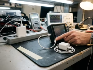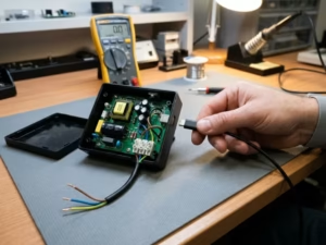
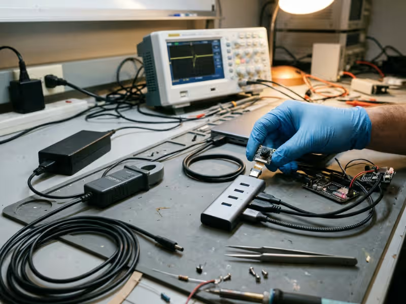
A client plugs a camera module into a USB hub. The other ports blink off. A board on the shared 5 V rail resets, and the adapter hiccups before it recovers.
Inrush current is the surge of current a discharged bulk capacitor draws the instant power connects.
That surge can trip protection, pit connector contacts, and brown out every device on a shared rail.
I help engineers trace these startup faults every week. This guide covers what causes inrush, how to tell it apart from overloads and shorts, which suppression method fits which case, and what to verify before production.
The Fastest Way to Recognize an Inrush Problem
Many teams blame a “bad adapter” or a “weak port” when the real cause is inrush. Before you swap any parts, look for three clues. A current probe and a few minutes on the bench will usually confirm it or rule it out.
It Strikes at Connection, Not During Steady Load
Inrush appears in the first few milliseconds after power connects. Once the input capacitors charge, the current drops back to its normal level.
Timing is your first test. Suspect inrush if the fault appears only when you plug in a device, hot-swap a card, or flip the power switch. If the fault appears an hour into steady operation, look somewhere else.
It Looks Like a Short, Then Fades
On a current probe, inrush looks alarming. A device with a few hundred microfarads of input capacitance can pull 10 A or more for a fraction of a millisecond.
A real short holds that high current until protection trips. Inrush fades as the capacitor fills. Without a limiter, that takes well under a millisecond. With one, it usually takes 1 to 10 ms.
So capture the whole event, not just the peak. A spike that decays on its own points to inrush. A current that stays flat at its maximum points to a fault.

It Shows Up as Droop, Resets, or Nuisance Trips
You rarely notice the current itself. You notice what it does to everything around it.
A shared 5 V rail sags, and a neighboring board resets. An adapter hiccups or latches off even though nothing downstream has failed. A hot-plug works on one try and fails on the next, depending on how fast someone seats the connector.
When I see a fault that changes with plug-in speed or temperature, I check for inrush first.
If you see… | Check for… |
|---|---|
Other devices reset when one plugs in | Rail droop during the inrush peak |
Adapter shuts down only at power-on | OCP tripping on capacitor charge current |
Hot-plug fails some of the time | Contact bounce combined with an unlimited surge |
Fuse or breaker opens only at startup | Peak current and I²t above the fuse rating |
Connector pins pitted or darkened | Repeated arcing at the moment of connection |
What Inrush Current Really Is
Once you suspect inrush, it helps to know what actually drives it. The physics fits in a few lines. Those few lines tell you which numbers to change when the surge gets out of hand.
Why an Empty Capacitor Grabs So Much Current
A capacitor resists any sudden change in its voltage. At the moment of connection, an empty bulk capacitor sits at 0 V. For that instant, it behaves almost like a dead short.
The source then pushes as much current as the path allows. Current keeps flowing until the capacitor voltage catches up with the supply. After that, only the normal load current remains.
What Sets the Peak and the Decay
Three things shape the surge: the supply voltage, the capacitance, and the total resistance in the path. That resistance includes source impedance, cable and connector resistance, and the capacitor’s own ESR.
Here is a quick example I use with clients:
- Peak current: A 5 V source feeds a 470 µF capacitor through 0.25 Ω of total resistance. The theoretical peak reaches about 20 A (5 V ÷ 0.25 Ω).
- Decay time: The time constant equals R × C, or about 120 µs. The surge fades within roughly five time constants, or about 0.6 ms.
On AC mains, the numbers grow fast. A 230 V line peaks near 325 V. Without a limiter, only the wiring, fuse, bridge diodes, and capacitor ESR stand in front of the bulk capacitor. The surge can reach tens of amps, and sometimes more than a hundred.
The energy also catches people off guard. Charging a capacitor burns as much energy in the series path as the capacitor stores. Your connector, fuse, and limiter absorb that heat on every plug-in.
Inrush vs. Overload vs. Short Circuit
Teams often lump these three together. That mistake leads to the wrong fix, such as a bigger fuse or a raised OCP threshold that weakens real fault protection.
Condition | What it looks like | What makes it different |
|---|---|---|
Inrush | High peak at connection that fades in milliseconds | Voltage recovers on its own and needs no fault |
Overload | Current runs 10% to 50% above rating for seconds or longer | Voltage stays mostly normal while heat builds slowly |
Short circuit | Very high current that holds steady | Voltage collapses and stays down until protection trips |
The time axis tells you which one you face. Capture at least 20 ms of current, and the waveform usually answers the question.
Where Inrush Causes Real Damage
One inrush event rarely kills anything. The damage comes from repetition. Every plug-in adds a little heat, a little arcing, and a little rail sag, and the bill arrives months later. I sort that damage into three places, because each one points to a different fix.
Inside the Adapter
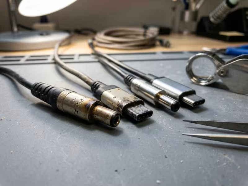
The connector takes the first hit. As the plug closes the last fraction of a millimeter, the contacts bounce and arc while the capacitor charges. Each arc melts a tiny spot of plating.
After a few hundred cycles, barrel or USB-C contacts turn dull gray, then pitted. In bad cases, two contact points micro-weld and tear apart on the next unplug.
The input parts suffer next. On an AC adapter, the bridge diodes and fuse absorb a 30 A to 50 A pulse at every cold start. Diodes with a thin surge rating (IFSM) crack after enough cycles. Fuses age too. Each pulse thins the element until one opens on a normal startup, with no fault anywhere.
Then come the nuisance shutdowns. A DC adapter with tight OCP sees the charge current, reads it as a short, and drops into hiccup mode. The customer reports an adapter that “dies” only when plugged into a loaded device.
On the Host Side
Host problems look stranger, because the victim is often not the device you just plugged in.
A shared 5 V or 12 V rail sags for a millisecond while the new load charges. A neighboring microcontroller dips below its brownout threshold and resets. An SSD or camera drops off the bus.
Port controllers can lock up as well. A USB or PCIe controller expects a clean rise on its supply pin. A sagging, bouncing rail can leave it in an undefined state. It stops responding until someone power-cycles the whole host.
Connector ratings get stretched quietly. A USB Type-A pin rated for 1.5 A may carry a 15 A spike on every insertion. On a backplane with 20 slots, that stress adds up fast.
Symptoms You’ll Actually Notice
In the field, nobody reports “excessive inrush.” They report odd behavior like this:
- Hot-plug works nine times, then fails on the tenth.
- Plugging in board B resets board A, even though the two share nothing but a supply rail.
- A connector passes inspection, yet its contact resistance creeps from 20 mΩ to 80 mΩ within a year.
- A port locks up when someone inserts the plug slowly, but works on a quick push.
That last one surprises most teams. A slow insertion stretches the bounce window and creates several partial surges in a row. A quick push delivers one clean event.
If a failure changes with how someone handles the plug, measure the surge before you replace any hardware.
The Main Ways to Suppress Inrush Current
Every suppression method does the same basic job. It adds resistance or time to the charging path, so the capacitor fills more slowly. The differences show up in cost, heat, and how the method behaves on the second plug-in.
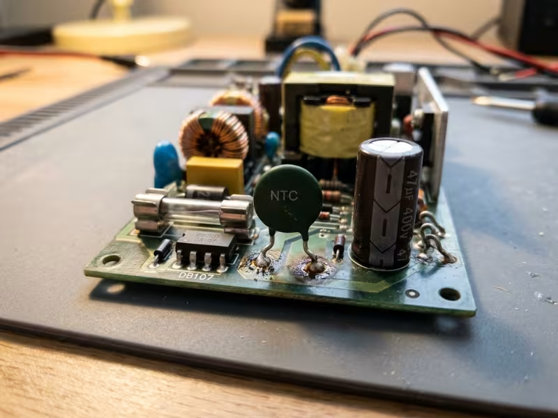
NTC Thermistors: Cheap and Simple, but Weak on Warm Restarts
An NTC thermistor starts cold with high resistance, often 5 Ω to 10 Ω. That resistance limits the first surge. Current then heats the part, and its resistance falls to a fraction of an ohm within seconds.
On a 230 V adapter, a 10 Ω NTC cuts a 325 V peak to about 32 A. Without it, the surge could run several times higher.
Where it works well: low-cost AC adapters and wall-powered devices that switch on a few times a day.
Main weakness: heat memory. A hot NTC can take a minute or more to cool back toward its cold resistance. Unplug and replug the device quickly, and the NTC still sits near its low resistance. You get almost no protection on the restart that needs it most. The part also wastes a little power and runs hot during normal operation.
Fixed Resistors: Predictable, but Always in the Way
A fixed series resistor limits current the same way every time. Temperature hardly changes it, so warm restarts behave like cold ones.
The cost comes during normal operation. A 2 Ω resistor carrying 1 A burns 2 W and drops 2 V. That works on small loads. On anything larger, designers add a relay or MOSFET that bypasses the resistor once the capacitor charges.
Where it works well: small adapters, often as a fusible wirewound resistor that also opens on a fault.
Main weakness: constant loss and voltage drop. Pick a resistor rated for pulse energy, not just steady watts, or it will crack on startup.
Active Limiters and Hot-Swap Controllers: Precise Control
An active limiter places a MOSFET in series with the input. A controller ramps the gate slowly, so the output voltage rises at a set rate. The charge current then follows a simple rule: current equals capacitance times the voltage ramp rate.
For example, 1,000 µF charged at 1 V/ms draws only 1 A. You choose the number.
Most hot-swap controllers also add a circuit breaker, a power-good signal, and latch-off or auto-retry on faults. They behave the same on the first plug-in and the hundredth.
Where it works well: USB hubs, PCIe slots, backplanes, and any port that sees frequent hot-plugging.
Main weakness: MOSFET stress. During the ramp, the MOSFET carries current and voltage at the same time. Check its safe operating area (SOA) carefully. Cost and board space also run higher.
Soft-Start Inside the Converter: Helpful, but Only Downstream
Most DC-DC converters and adapter controllers include soft-start. They ramp the output over 1 to 10 ms, which limits the charge current into the output capacitors.
Where it works well: keeping output-side surges small, especially with large capacitor banks on the load.
Main weakness: it does nothing for the input capacitors. Those caps sit ahead of the converter and charge the instant power connects. Many teams see “soft-start” on a datasheet and assume inrush is solved. It usually isn’t.
Why a PTC Can’t Replace an NTC
These two parts get mixed up all the time. They do opposite jobs.
A PTC starts with low resistance and rises when it heats up. At the moment of connection, it is cold and nearly invisible to the surge. It only trips during a sustained overcurrent that lasts milliseconds to seconds.
So a PTC works as a resettable fuse for fault protection. It never limits inrush. Use it alongside an inrush limiter, not in place of one.
Method | Best for | Main strength | Main weakness |
|---|---|---|---|
NTC thermistor | Low-cost AC adapters with rare power cycles | Cheap, small, easy to add | Little protection on warm restarts |
Fixed resistor | Small adapters and low-current inputs | Same behavior hot or cold | Constant loss and voltage drop |
Active limiter / hot-swap controller | Hot-plug ports, backplanes, shared rails | Precise, repeatable, adds fault control | Cost, board area, MOSFET SOA limits |
Converter soft-start | Large output capacitor banks | Built into most controllers | Doesn’t limit input capacitor surge |
PTC | Sustained overcurrent faults | Resets after the fault clears | Doesn’t limit inrush at all |
Choosing the Right Suppression Method by Application
No single method wins everywhere. The right choice depends on where the surge comes from, how often the device connects, and how much loss you can accept. I sort projects into four groups, and each one has its own trap.
Low-Power Adapters and Simple Wall-Powered Devices
Where the surge comes from: the bulk capacitor behind the bridge rectifier. If someone plugs in at the peak of the AC sine wave, a 264 VAC line hits that capacitor with about 373 V.
What usually works: a small NTC or a fusible wirewound resistor. Most wall adapters and USB PD chargers power on only a few times a day, so the NTC’s heat memory rarely matters.
What usually fails: a fuse with too little I²t margin, or bridge diodes with a thin surge rating. Neither fails on day one. Both wear out after a few thousand cold starts.
What I check first: the peak current at high line, with the plug closing near 90° on the sine wave. Then I unplug for five seconds, plug back in, and measure again. If the second peak runs far higher than the first, the NTC alone isn’t enough.
Hot-Pluggable Ports and Backplanes
Where the surge comes from: the input capacitance of the card or device you plug into a live rail. The host supply stays on, so every neighbor on that rail feels the dip.
What usually works: a hot-swap controller or a load switch with a set slew rate. On USB, the device side matters too. USB 2.0 limits attach capacitance to about 10 µF, so a device that needs more must hide the rest behind its own soft-start switch.
What usually fails: NTCs, PTCs, and “the host fuse will handle it.” None of them control the charge rate, and none of them act fast enough to protect the shared rail.
What I check first: droop on a neighboring port during a slow, wobbly insertion. A quick push often looks fine. A slow one exposes the problem.
High-Capacitance Loads and Motor-Related Systems
Where the surge comes from: large DC bus capacitor banks, often several thousand microfarads on a 24 V or 48 V supply.
What usually works: a precharge resistor with a relay or MOSFET bypass, or a MOSFET linear ramp stretched over 50 ms to 200 ms.
What usually fails: a hot-swap controller sized for a small card. The math catches people. A 4,700 µF bus at 48 V stores about 5.4 J, and the series MOSFET burns roughly the same 5.4 J while charging it. A small MOSFET can’t survive that in a short ramp.
What I check first: MOSFET SOA at the real ramp time and the hottest expected case temperature. I also confirm that the controller’s fault timer won’t expire before the bus finishes charging.
Battery-Powered and Portable Devices
Where the surge comes from: the battery itself. A charged lithium cell has an internal resistance of only tens of milliohms. When a user inserts the pack or a power switch closes, nothing slows the charge into the board’s capacitors.
What usually works: a load switch with a controlled rise time, often around 1 ms, placed right after the battery connection.
What usually fails: NTCs and fixed resistors. They waste energy the battery can’t spare, and they cause voltage drop at low charge. Another common miss is the battery’s own protection IC. Its short-circuit detection can read the inrush as a fault and cut power within a few hundred microseconds.
What I check first: whether the BMS trips at power-on with a fully charged pack at room temperature and with a cold pack. A device that “won’t turn on sometimes” often has this problem.
Application | Typical inrush issue | Preferred approach | Watch-out |
|---|---|---|---|
Low-power AC adapters | High-line surge into the bulk capacitor | NTC or fusible resistor | Weak protection on quick replug |
Hot-plug ports and backplanes | Rail droop that resets neighbors | Hot-swap controller or slew-controlled load switch | Slow insertions and contact bounce |
High-capacitance motor loads | Large bus charge energy | Precharge with bypass, or long MOSFET ramp | MOSFET SOA and fault timer limits |
Battery-powered devices | Very low source impedance | Load switch with controlled rise time | BMS short-circuit trip at power-on |
Match the method to the connection pattern first, and the power level second. A part that suits a wall adapter can fail badly on a busy hot-plug port.
How to Design and Verify Inrush Suppression
Picking a limiter is easy. Proving it works on the hundredth plug-in, on a hot day, at the worst point of the AC wave is the hard part. I run every design through the same five checks, in this order, because each one depends on the number from the step before.
Estimate the Surge Before You Pick Parts
Start with three numbers: the source voltage, the input capacitance, and the total resistance in the charging path. That resistance includes source impedance, cable, connector contacts, and capacitor ESR.
- Unlimited peak: divide voltage by total resistance. A 24 V source, 220 µF, and 0.1 Ω of path resistance gives a theoretical 240 A. The source will sag before it delivers that much, but the number shows you have a problem.
- Charge time: about five times R × C.
- Target current with an active limiter: current equals capacitance times ramp rate. To hold 220 µF to 2 A, ramp at about 9 V/ms. The rail then reaches 24 V in roughly 2.6 ms.
Write down your target peak and your allowed startup delay. Every later check depends on those two numbers.
Size the Limiter for Energy, Not Steady Current
The limiter absorbs about as much energy as the capacitor stores, ½CV². For 220 µF at 24 V, that comes to about 63 mJ per plug-in.
- NTC thermistors: check the maximum capacitance rating at your line voltage, not just the steady current. Most datasheets list it. Exceed it, and the part cracks.
- Resistors: use a wirewound or fusible type with a published pulse rating. Standard SMD chip resistors often fail on the first hard startup.
- MOSFETs: 63 mJ over 2.6 ms means about 24 W of average power. Find that point on the SOA curve at the matching pulse width. Then derate it, because the curves assume a 25 °C case and your board runs hotter. Modern trench MOSFETs often show weak linear-mode SOA, so check this early.
Coordinate With Fuses and Protection Thresholds
A good limiter can still look like a fault to the parts around it. Check each threshold against the inrush you measured.
- Fuse I²t: for an exponential surge, I²t equals roughly peak current squared times RC, divided by two. Many fuse makers suggest you keep repeated pulses at 20% to 40% of the fuse’s melting I²t, depending on cycle count.
- OCP and breakers: set the limited charge current well below the adapter’s OCP point, or confirm that the OCP blanking time covers the full ramp.
- Hot-swap fault timer: the timer must outlast the charge time with margin. Otherwise the controller latches off on every normal startup.
Don’t raise a threshold to hide a surge. Lower the surge instead.
Test Repeated Plug-In and Reconnect Behavior
One clean cold start proves very little. I run this sequence with a current probe and at least a 20 ms capture window:
- Cold start at low line and high line
- Warm restart: run at full load for 30 minutes, unplug for 2 to 5 seconds, and replug
- AC insertion at 90° and 270° on the sine wave, using a phase-controlled source
- 100 or more plug cycles with the real cable, half fast and half slow
- Hot-plug into a live rail while you watch a loaded neighbor port for droop
- The same tests at the coldest and hottest rated temperatures
Log the worst peak, not the average.
Place the Limiter in the Real Surge Path
This is the mistake I find most often on schematic reviews. Someone adds a 47 µF capacitor on the connector side “for stability,” or an EMI filter capacitor ahead of the NTC. That capacitor charges straight from the source, and the limiter never sees its current.
Trace every capacitor tied to the input pins. Anything between the connector and the limiter charges unlimited. Keep that side to small ceramics of a few microfarads at most. Then confirm the waveform at the connector itself, not just at the limiter output.
Common Mistakes That Make Inrush Worse
Most inrush failures I review don’t start with a bad part. They start with a reasonable shortcut that pushes the problem somewhere harder to see. These five mistakes show up on schematics and bench reports again and again.
Reaching for a Bigger Fuse
A fuse opens on a normal startup, so someone swaps the 2 A fuse for a 4 A one. The symptom disappears, and the team moves on.
The surge itself never changed. It still pits the connector, stresses the bridge diodes, and sags the shared rail. The bigger fuse also clears real faults more slowly. A shorted capacitor that once opened a 2 A fuse in milliseconds can now cook a trace before the 4 A part reacts.
A fuse that fails at startup is giving you a measurement, not showing you a defect. Find the peak and fix the surge.
Testing Only Cold Starts
Most bench tests begin with a cold unit fresh off the shelf. The NTC sits at full resistance, and the peak looks fine.
Real users unplug a hot adapter and plug it straight back in. I once measured a 65 W adapter that peaked at 28 A cold and 70 A after a 3-second replug at full load. That second surge welds contacts and opens fuses in the field.
Always add a warm restart to the test plan. If the replug peak runs more than about twice the cold peak, add a bypass relay or move to an active limiter.
Placing the Limiter After the Wrong Node
Designers often place the limiter where it fits on the layout, not where the current actually flows.
Multi-rail boards cause this most often. The hot-swap MOSFET protects the main rail, but a standby regulator taps power straight from the connector, ahead of the limiter. Its 100 µF input capacitor charges with no limit on every plug-in. The main rail looks perfect on the scope, yet the connector still arcs.
Draw the path from the input pins to every capacitor on the board. The limiter must sit in series before all of them.
Checking Connector Ratings Too Late
Teams pick connectors early, based on steady current. They measure inrush months later, after the PCB is finished.
A continuous rating doesn’t cover make-and-break pulses. A pin rated for 3 A might see a 20 A spike as its contacts close. On a multi-port hub, a shared ground pin can carry the combined surge of several ports at once.
Ask the connector maker for pulse or hot-plug ratings during the schematic stage. Changing a connector after tooling costs far more than adding a limiter.
Trusting the Adapter to Protect the Host
The adapter datasheet lists an NTC and soft-start, so the host team skips its own limiting. This is the mistake I argue about most.
The adapter’s protection only limits its own capacitor on the AC side. Once the adapter is running, its output looks like a stiff, low-impedance source. Plug the DC barrel into the host, and the adapter’s output capacitors dump straight into the host’s input capacitors. The adapter’s OCP may then trip into hiccup mode, and the host gets blamed for “not booting.”
Customers also swap in third-party adapters you never tested. Even when you ship a matched custom power adapter, the host owns its input capacitance. So the host needs its own load switch or hot-swap controller.
Standards and Compliance: What Matters, and What Does Not
Clients often ask me which standard “covers” inrush. The honest answer is that several specs touch it, but none of them design your limiter for you.
Which Specs May Touch Inrush Behavior
A few standards come up on almost every project I review:
- IEC 61000-4-5 and IEC 61000-4-11: The surge test checks whether your NTC, fuse, and input diodes survive line spikes. The dips and interruptions test drops the mains briefly, which forces a restart with a warm limiter. That makes it one of the few lab tests that touches reconnect behavior.
- IEC 61000-3-3: This standard limits the voltage change a product causes on the mains at switch-on. Large inrush can push you over it.
- USB-IF specs: USB 2.0 caps a device’s attach capacitance at about 10 µF. Anything larger needs a soft-start switch.
- PCI-SIG specs: Add-in cards must stay within slot power limits. In practice, hot-plug designs rely on a hot-swap controller to keep startup current under control.
- UL/IEC 62368-1: This standard covers most ITE power supplies and adapters. Safety testing checks component ratings and single-fault behavior. A cracked NTC or overstressed fuse can fail you here.
Why Bench Testing Still Matters More Than the Logo
A safety certificate proves the product won’t shock anyone or start a fire under the test conditions. It doesn’t prove your limiter works on a 3-second warm replug. It also says nothing about the 500th hot-plug into a loaded rail.
Labs test a few samples, a few times. Your customers plug in thousands of times.
So treat the certificate as a minimum requirement, not a design check. Measure the surge yourself, log the worst case, and keep those waveforms with your compliance file.
FAQ
These six questions come up in nearly every startup fault review I join. Here are the short answers I give engineers.
What is an acceptable inrush current limit for a USB port?
USB 2.0 limits a device’s attach capacitance to about 10 µF, and compliance testing caps the charge it pulls at connection to around 50 µC. If your design needs more bulk capacitance, put it behind a load switch with a controlled rise time. On the host side, I aim to keep droop on neighboring ports small enough that no device resets.
How do I calculate inrush current from capacitance?
For an unlimited surge, divide the source voltage by the total path resistance. That resistance includes source impedance, cable, contacts, and ESR. The surge fades in about five times R × C.
With an active limiter, use current equals capacitance times ramp rate. For example, 1,000 µF ramped at 1 V/ms draws about 1 A. I always confirm the result with a current probe.
Does an NTC thermistor work after a quick power cycle?
Not well. A hot NTC can take a minute or more to cool back toward full resistance. If someone unplugs a hot unit and plugs it back in within a few seconds, the NTC barely limits the surge. I’ve measured replug peaks more than double the cold-start peak. If your product sees quick restarts, add a bypass relay or use an active limiter.
What is the difference between inrush protection and overcurrent protection?
Inrush protection slows a normal, expected surge at startup. Overcurrent protection catches abnormal current from overloads and shorts. They work together. Never raise an OCP threshold to hide inrush, because that weakens your real fault protection.
Can inrush current damage an AC adapter?
Yes, and the damage builds up over time. Each cold start sends a pulse of 30 A or more through the bridge diodes, fuse, and connector. After thousands of cycles, fuses open on normal startups, diodes crack, and contacts pit. An undersized NTC can also crack on the first hard surge.
When should I use a hot-swap controller instead of a thermistor?
I choose a hot-swap controller when a device plugs into a live, shared rail, connects often, or must handle quick restarts. It gives the same limit on every plug-in, along with fault timing and a power-good signal. I save thermistors for low-cost AC adapters that power on only a few times a day.
Measure the Surge Before You Choose the Fix
Inrush lasts only a few milliseconds. That short window can still trip OCP, open fuses, pit connector contacts, and reset boards on a shared rail. The damage builds quietly, one plug-in at a time.
No single limiter fits every product. A wall adapter that powers on twice a day can live with a small NTC. A busy hot-plug port or a 48 V motor bus needs an active limiter with a controlled ramp. Let the power level, the restart pattern, and the hot-plug duty pick the method.
A datasheet line or one clean cold start proves very little. The warm replug, the slow insertion, and the high-line peak show what your design really does.
This week, put a current probe on your worst-case hot-plug event. Then compare the measured peak against your fuse, connector, and MOSFET ratings.