Selecting the right AC-DC power supply requires evaluating input voltage range, output power headroom, thermal derating, form factor, and compliance certifications in sequence. Skipping any one of these steps risks field failures, certification delays, or costly redesigns. This guide walks engineers and procurement managers through a proven seven-step selection framework—with a practical sizing example and application-specific guidance for medical, industrial, and IoT designs.
Choosing an AC-DC power supply is rarely as straightforward as matching a voltage and wattage rating on a datasheet. Engineers who have gone through a product recall—or watched a design fail EMC pre-scan two weeks before launch—know exactly why. The power supply sits at the foundation of every electronic system. Get it right, and it becomes invisible. Get it wrong, and everything downstream suffers.
The challenge is that selection decisions compound quickly. Input voltage range, output current, thermal environment, mechanical form factor, and certification requirements all interact. A unit that passes every electrical check may still fail in a 70°C enclosure, or lack the isolation class required for a Class II medical application. Procurement managers face a parallel set of pressures: long-term component availability, supplier financial stability, and total cost of ownership—not just unit price.
This guide provides a structured, seven-step framework for selecting AC-DC power supplies. Each step addresses a specific decision layer, with technically precise criteria and a worked sizing example to ground the process in practice. Application-specific guidance for medical, industrial/communications, and smart home/IoT designs is included, followed by a review of the most common—and most costly—selection mistakes.
Whether you are specifying a power supply for a new design or re-evaluating an existing BOM, this guide gives you the criteria to make an informed, defensible decision.
What to Know Before You Select an AC-DC Power Supply
Before diving into individual parameters, it helps to understand the decision sequence. Power supply selection follows a layered logic: each step constrains the options available in the next. Trying to optimize the form factor before confirming compliance requirements often leads to backtracking.
The five-layer decision sequence looks like this:
- Electrical requirements — input range, output voltage, current, and power
- Environmental conditions — operating temperature, altitude, humidity, and derating
- Mechanical constraints — form factor, mounting style, and enclosure fit
- Regulatory requirements — safety certifications, EMC compliance, and isolation class
- Vendor and lifecycle factors — reliability data, support duration, and supply chain depth
Working through these layers in order prevents the most common rework scenarios. With that framework established, here is how to execute each step.
Step 1 — Define Input Voltage and Target Markets
The first decision is the input voltage range, which is directly tied to where the product will be sold.
Most of the world operates on 100–240 VAC, 50/60 Hz. This includes North America (120 VAC nominal), Europe (230 VAC nominal), Japan (100 VAC nominal), and most Asia-Pacific markets. Specifying a universal input range—typically expressed as 85–264 VAC in the datasheet—covers the full envelope with margin at both ends, accommodating brownout conditions and line transients.
One important clarification: the 85–264 VAC range is the operating specification of a universal-input supply. The nominal input voltages in target markets—120 VAC in North America, 230 VAC across most of Europe—fall well within that window. These two numbers describe different things and should not be conflated in a specification document.
Selecting a universal input range simplifies global distribution. It eliminates the need for region-specific SKUs and removes a product variant from inventory management. For most applications, this is the right starting point unless cost constraints make a narrow-range design necessary for a single-market product.
For DC-input applications—such as telecom rectifiers or battery-backed systems—the input range analysis shifts to the expected DC bus voltage and its variation under load and fault conditions.
Step 2 — Match Output Voltage, Current, and Power Headroom
Once the input range is defined, calculate the required output power with headroom—not to the rated maximum.
A common rule of thumb is to size for 70–80% of rated output power under typical operating conditions. This leaves thermal headroom, extends component life, and provides margin for load transients. Running a power supply continuously at 100% rated load compresses its operating margin and accelerates capacitor aging.
Worked example: A 24 VDC industrial controller draws 3.5 A under normal operation, with occasional peaks of 4.2 A during motor startup. Peak power is 24 V × 4.2 A = 100.8 W. To stay within 80% of rated capacity at peak, the minimum rated output power is 100.8 ÷ 0.8 = 126 W. In this case, specifying a 150 W unit at 24 VDC is appropriate. During normal conditions, the supply operates at approximately 84 W—56% of rated output—providing substantial thermal and lifetime headroom.
For multi-rail designs, calculate each rail independently and confirm the supply’s total output power specification covers the combined load. Some power supplies have per-rail current limits that are more restrictive than the aggregate power rating. Read the datasheet carefully.
Step 3 — Check Thermal Derating and the Real Operating Environment
Datasheet power ratings are typically specified at 40°C or 50°C ambient. Above that threshold, most power supplies derate linearly—often losing 2–2.5% of rated output power per degree Celsius above the rated temperature. At 70°C ambient, a 150 W unit rated to 50°C may reliably deliver only 100–110 W.
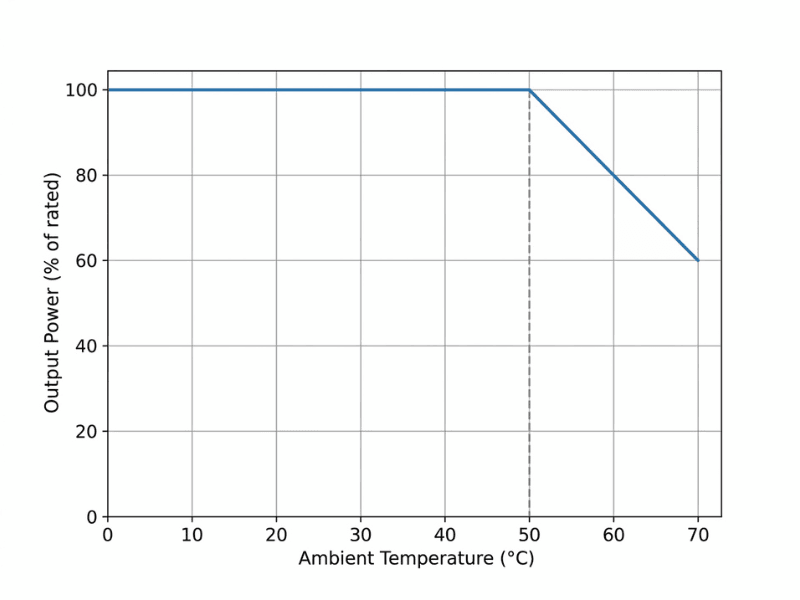
This is one of the most frequently overlooked steps in the selection process and one of the most consequential.
To apply derating correctly:
- Identify the maximum ambient temperature inside the enclosure—not the external environment. Internal temperatures are often 10–20°C higher than ambient due to heat generated by other components.
- Find the derating curve in the datasheet, not just the maximum operating temperature.
- Calculate the derated output power at the actual operating temperature and confirm it still meets your load requirements.
Altitude also affects thermal performance. Above 2,000 meters, reduced air density lowers convective cooling efficiency. Some certifications—IEC 60950, IEC 62368—include specific altitude derating requirements that must be accounted for in high-altitude deployments.
Electrolytic capacitor performance is another thermal consideration. At low temperatures, typically below –10°C to –20°C, electrolytic capacitors experience a measurable increase in equivalent series resistance (ESR) and a decrease in effective capacitance. This can affect output ripple and startup regulation in cold environments. For applications operating below –20°C, confirm that the selected supply’s capacitors are rated for low-temperature operation and review the startup specification at minimum temperature.
Step 4 — Choose the Right Form Factor and Mounting Style
AC-DC power supplies come in several mechanical formats, each suited to different integration scenarios:
- Open-frame / PCB-mount: Maximum flexibility for custom enclosure integration. Requires the system enclosure to provide IP protection and user access safety. Common in industrial and medical equipment.
- Enclosed / chassis-mount: Self-contained with its own housing. Suitable for DIN rail, panel mount, or free-standing installation. Easier to integrate in retrofit or field-installed applications.
- DIN rail: Standard in industrial control panels and building automation systems. Snap-mount installation simplifies assembly and replacement.
- PCB plug-in modules: Compact form factor for space-constrained designs, particularly relevant for IoT and smart home hardware.
- External adapter (desktop/wall-plug): Common in consumer electronics and low-power embedded systems. Simplifies end-product certification by separating the power conversion stage.
The key constraint is whether the application requires the power supply to contribute to the product’s IP or safety rating, or whether the system enclosure handles those requirements. Open-frame supplies offer more flexibility but impose more design responsibility on the system integrator.
Step 5 — Verify Safety and Compliance Requirements
Certification requirements vary by application domain and target market. Selecting a power supply that lacks a required certification—or carries the wrong safety class—can block product launch entirely.
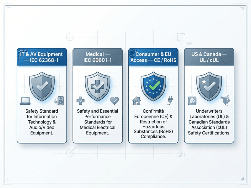
Key certifications to verify:
- IEC 62368-1: The current harmonized safety standard for audio/video, information technology, and communication equipment. Has largely replaced IEC 60950-1 and IEC 60065 in most markets.
- IEC 60601-1: Required for medical electrical equipment. Specifies isolation requirements (MOPP—Means of Patient Protection), leakage current limits, and dielectric strength. Leakage current limits vary by the level of patient contact: devices with no direct patient contact have different limits than those with patient-applied parts. Confirm the specific leakage class required for your application.
- UL/cUL: Required for US and Canadian markets. UL 62368-1 is the current relevant standard for most electronics; UL 60601-1 for medical.
- CE marking: Required for EU market access, covering the Low Voltage Directive and EMC Directive.
- FCC Part 15 / CISPR 32: EMC emissions requirements for the US and international markets, respectively.
- RoHS and REACH: Material compliance requirements for EU market access.
Always verify that certifications listed on the datasheet cover the specific output power and configuration you intend to use. Some certifications apply only to a subset of configurations within a product family.
Step 6 — Evaluate Reliability, Lifetime, and Long-Term Support
A power supply that meets all electrical and regulatory requirements on day one still needs to support the product through its intended operational life.
The standard reliability metric is MTBF (Mean Time Between Failures), typically calculated using MIL-HDBK-217F or Telcordia SR-332 methodologies. A higher MTBF does not guarantee individual unit longevity, but it is a useful comparative metric when evaluating designs at similar operating conditions. Always confirm which standard and operating conditions were used when comparing MTBF figures across suppliers.
Component lifetime—particularly electrolytic capacitors—is the practical limiting factor in most power supply designs. Capacitor lifetime roughly halves for every 10°C increase in operating temperature, following the Arrhenius relationship. A supply operating at lower junction temperatures will typically outlast one operating near its thermal limits, even if both have identical MTBF specifications.
For long-lifecycle products—industrial equipment, infrastructure, medical devices—confirm the supplier’s policy on product longevity and last-time-buy notification. A seven-to-ten-year product lifespan is standard in industrial markets; longer support commitments require explicit confirmation from the manufacturer.
Step 7 — Compare Vendors Beyond the Datasheet
Two power supplies can share nearly identical datasheets and deliver very different outcomes in production and the field. Evaluating vendors requires looking past headline specifications.
Key factors to assess:
- Manufacturing quality systems: ISO 9001 certification is a baseline. Look for IPC-A-610 workmanship standards and AOI/X-ray inspection processes.
- EMC design heritage: Suppliers with strong EMC engineering teams tend to produce designs that pass first-pass pre-compliance testing more reliably. Request representative EMC test reports.
- Application engineering support: Can the supplier provide derating curves for your specific operating conditions? Will they support custom output voltages or modified form factors?
- Supply chain depth: Single-source critical components are a supply chain risk. Ask suppliers about their component sourcing strategy and buffer stock practices.
- Financial and operational stability: For long-lifecycle products, supplier continuity matters. Evaluate years in operation, production capacity, and geographic distribution of manufacturing.
How to Select an AC-DC Power Supply by Application Type
What isolation class and leakage limits apply to medical applications?
Medical power supply selection begins with patient risk classification. IEC 60601-1 defines three levels of patient-applied part—Type B, BF, and CF—each with progressively stricter leakage current limits. A supply suitable for a Class B application with no direct patient contact may not meet the requirements for a CF-type application involving direct cardiac contact.
Key requirements for medical power supplies:
- 2 MOPP (Means of Patient Protection) isolation between input and output for most patient-contact applications
- Earth leakage current within the limits specified for the relevant patient-applied-part type
- EMI/EMC compliance to CISPR 11 or equivalent
- Reinforced insulation with high dielectric strength
Always specify the exact patient contact type and operating environment to your supplier before selecting a unit so the correct isolation and leakage class can be confirmed.
What makes a power supply suitable for industrial and communications environments?
Industrial environments introduce vibration, wide temperature swings, conducted electrical noise, and potentially corrosive atmospheres. Key selection criteria include:
- Wide operating temperature range, typically –40°C to +70°C or beyond
- High immunity to conducted and radiated interference per IEC 61000 series
- DIN rail or panel-mount form factors for control panel integration
- Conformal coating options for humid or corrosive environments
- Input surge withstand capability per IEC 61000-4-5
Telecom and communications infrastructure often also requires compliance with regional carrier specifications, such as GR-CORE for North American telecom equipment.
How do you balance cost, size, and compliance for smart home and IoT designs?
Smart home and IoT designs face intense pressure on both cost and physical footprint, but cannot sacrifice safety compliance—particularly given increasing regulatory scrutiny of connected consumer devices in the EU and North America.
Compact enclosed or PCB plug-in modules are typically the right form factor. Key considerations:
- No-load power consumption: Standby power limits—as set by EU Regulation 2019/1782 and US DOE Level VI, the current reference standards—must be met at the product level. The power supply’s no-load consumption directly affects system standby performance.
- EMC at low power levels: Compact high-frequency switching designs require careful EMC filtering. Confirm pre-compliance test data before committing to a design.
- Cost vs. certification trade-off: For consumer market access in the EU and US, CE and FCC/UL certifications are non-negotiable. Budget for certification costs in the product cost model.
Common Mistakes When Choosing an AC-DC Power Supply
Even experienced engineers make selection errors. These are the most frequently encountered—and most preventable.
- Sizing to rated maximum rather than derated operating point. A 150 W supply running at 150 W in a 65°C enclosure is a reliability problem waiting to happen. Always derate for the real operating environment before finalizing a selection.
- Confusing nominal input voltage with operating range. A supply rated for 85–264 VAC operates across all major global utility voltages without modification. A supply rated for 220–240 VAC does not. Read the specification carefully and verify it covers your actual input conditions.
- Assuming one certification covers all markets. CE marking does not satisfy FCC requirements. UL certification is not equivalent to TÜV. Map certification requirements to each target market explicitly before supplier selection.
- Overlooking the derating curve. The maximum operating temperature on a datasheet is not the temperature at which full rated power is available. Always locate and apply the derating curve to your actual operating temperature.
- Selecting based on unit price alone. A lower-cost supply that requires additional filtering, fails an EMC pre-scan, or needs early replacement in the field is not a cost-saving. Evaluate total cost of ownership across the product’s intended lifespan.
- Not confirming long-term availability. For products with multi-year production runs, confirm the supplier’s product longevity policy and last-time-buy notification process before finalizing the BOM.
Making the Right Power Supply Decision
AC-DC power supply selection is a structured engineering problem, not a lookup exercise. The seven-step framework in this guide—input range, output sizing with headroom, thermal derating, form factor, compliance verification, reliability evaluation, and vendor assessment—addresses each decision layer in the sequence it matters.
The worked example in Step 2 illustrates a principle that applies across all specifications: build in margin. A system sized to operate comfortably below its thermal and electrical limits will consistently outperform one pushed to its rated edge.
For complex or custom requirements—such as modified output voltages, non-standard form factors, or high-volume OEM applications—working directly with a manufacturer’s application engineering team early in the design process helps avoid the most costly selection errors. Quankang’s engineering team supports design-in consultations for industrial, medical, and IoT applications, with custom specification support available for qualified OEM and ODM programs.
Use this guide as a checklist for every new power supply selection. Working through it systematically takes thirty minutes. A field failure or certification delay costs considerably more.
[Contact Quankang’s engineering team to discuss your application requirements.]
Frequently Asked Questions
What is the difference between an 85–264 VAC and a 100–240 VAC input range specification?
Both describe universal-input AC-DC power supplies, but with different operating margins. A 100–240 VAC rating covers nominal voltages across global markets. An 85–264 VAC rating adds margin for brownout conditions and overvoltage transients. For applications where line quality is variable or uncertain, the wider 85–264 VAC range provides additional protection.
How much power headroom should I design into an AC-DC power supply selection?
A commonly applied guideline is to size the power supply so that the maximum expected load does not exceed 70–80% of the supply’s rated output power at the actual operating temperature after derating. This provides margin for load transients, component aging, and thermal variation. The appropriate headroom depends on the specific application and the criticality of continuous operation.
Do I need separate power supplies for different countries?
Not if you select a universal-input supply rated for 100–240 VAC or 85–264 VAC. These units operate across all major global utility voltages without modification or adjustment. Country-specific supplies—rated for a single nominal voltage—are only appropriate for products sold in a single market where the cost savings justify the loss of flexibility.
What certifications does a medical power supply require?
At minimum, IEC 60601-1 for safety and IEC 60601-1-2 for EMC are required for medical electrical equipment. The specific isolation class—and leakage current limits—depends on the type of patient-applied part (B, BF, or CF). Market-specific certifications such as UL 60601-1 for North America and CE under the MDR for Europe are additional requirements for global distribution.
What does MTBF actually indicate about a power supply’s reliability?
MTBF is a statistical measure of a population of units, not a prediction of how long any individual unit will last. A higher MTBF indicates a lower failure rate across a population under the specified test conditions. When comparing MTBF values across suppliers, confirm that the same calculation methodology—MIL-HDBK-217F or Telcordia SR-332—and the same operating conditions were used. MTBF figures calculated at 25°C full load are not directly comparable to those calculated at 40°C at 50% load.
How do I evaluate a power supply vendor beyond the datasheet?
Request EMC pre-compliance test data for representative products. Confirm which safety certifications apply to the specific configuration you need. Ask about component sourcing practices and last-time-buy notification policies. For high-volume or long-lifecycle applications, assess manufacturing quality systems—ISO 9001 and IPC-A-610 compliance—and the supplier’s track record with customers in your industry.