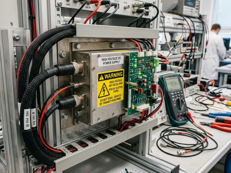
Your phone charger puts out 5 volts. The wall outlet behind it delivers 120. A hospital X-ray tube requires anywhere from 40,000 to 150,000 volts just to produce a single image. The device that makes that jump possible is a high-voltage power supply, and once you start looking, you’ll find one behind an enormous range of technologies—most of which you’d never associate with the word “voltage.”
This guide covers what high voltage power supplies actually do, how they create and control extreme voltages, what’s inside them, where they’re used, and what it takes to work around them safely. No electrical engineering background required.
Why Do Some Technologies Need Thousands of Volts?
The easiest way to understand this is to separate voltage from current. Voltage is electrical pressure. Current is how much charge flows. A pressure washer and a garden hose can move similar amounts of water, but only one strips paint—because of the force behind the stream, not the volume.
Some technologies depend on that force, not the flow. They need a strong push, not a large quantity of charge. High voltage shows up when the job is one of three things:
- Accelerating particles. Electrons need enormous voltage to gain enough energy to generate X-rays or resolve fine structure in an electron microscope. At 100 kV, an electron travels at more than half the speed of light.
- Creating strong electric fields. A powerful field can charge soot particles so they stick to collector plates inside a smokestack, or charge paint powder so it wraps evenly around a car body—including the back side you couldn’t spray directly.
- Stressing gases or insulators on purpose. Plasma systems, CO₂ lasers, and high-voltage insulation testers all work by pushing a material to its electrical limit: either ionizing a gas to create a conductive plasma, or proving that an insulator can survive a worst-case voltage event.
Here’s the detail that surprises most people: none of these jobs need much current. A 30,000-volt laboratory supply might deliver just 1 milliamp, working out to roughly 30 watts—less than a typical light bulb. High voltage and high power are entirely different things, and conflating them is probably the most common mistake beginners make. Hold that distinction in mind and the rest of this guide falls into place quickly.
What Is a High Voltage Power Supply?
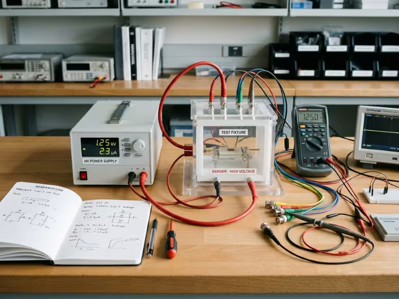
A high voltage power supply converts a lower-voltage input—usually AC mains or a low-voltage DC source—into a stable, adjustable high voltage output, typically at limited current. The working analogy is a pressure booster for electricity: it takes the modest “pressure” available at a wall outlet and raises it by hundreds or thousands of times, while holding the result steady enough for precision instruments.
What Counts as “High Voltage”?
International standards (IEC) draw the line at 1,000 V AC or 1,500 V DC. In practice, engineers use the term more loosely. A “high voltage power supply” might mean anything from a few hundred volts to several hundred kilovolts, depending on the field.
A rough sense of the scale:
- 500–2,000 V: biasing radiation detectors and photomultiplier tubes
- 10–30 kV: electrospinning, scanning electron microscopes, lab instruments
- 40–150 kV: medical and dental X-ray
- Hundreds of kV and up: particle accelerators and large industrial installations
How It Differs from an Ordinary Power Supply
An HV supply and a laptop adapter share the same fundamental goal—convert and regulate electrical power—but the engineering challenges are almost entirely different.
Ordinary Power Supply | High Voltage Power Supply | |
|---|---|---|
Typical output | 5–48 V | Hundreds of V to hundreds of kV |
Typical current | Several amps | Microamps to milliamps |
Main design challenge | Efficiency and thermal management | Insulation integrity and arc control |
Common failure risk | Overheating components | Insulation breakdown, internal arcing |
How output is measured | Directly | Indirectly, via precision resistor dividers |
Insulation drives almost every unusual design choice in an HV supply. Air breaks down at roughly 3 kV per millimeter under ideal lab conditions—and far less in humid or contaminated environments. A 30 kV output requires centimeters of clearance or thoroughly encapsulated conductors around every live point. Arcing, in this context, isn’t a catastrophic fault to be prevented at all costs. It’s a predictable operating event that the supply has to be designed to absorb and recover from.
How Does a High Voltage Power Supply Work?
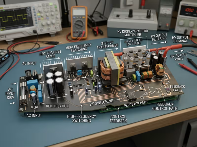
Most modern HV supplies use a switch-mode architecture built around five sequential stages: convert the input to DC, switch it at high frequency, step the voltage up, convert it back to smooth DC, and continuously measure and correct the output. Understanding each stage takes less time than it might sound.
The signal path looks like this:
AC Input → Rectify to DC → Switch at High Frequency → Step Up via Transformer → Rectify and Filter → DC High Voltage Output, with a feedback loop running back from the output to the switching stage.
Stage 1: Input Rectification
The process begins by turning AC mains into a steady DC voltage. A 120 V AC supply is rectified and filtered to roughly 170 V DC—that’s the peak of the AC waveform, not the RMS value you read on the outlet. Supplies designed for DC input (24 V from an industrial cabinet, for example) skip this step entirely.
Stage 2: High-Frequency Switching
This is the stage that separates modern HV supplies from their predecessors. An inverter made of fast transistor switches—MOSFETs or IGBTs—chops the DC bus into high-frequency AC, typically between tens and hundreds of kilohertz.
Why does frequency matter? Transformer size scales inversely with frequency. A transformer running at 50 or 60 Hz (mains frequency) needs a large, heavy iron core. Run the same design at 50 kHz and the core can be a fraction of the size and weight. That’s why a 30 kV supply that once occupied a floor-standing cabinet can now be built into a module about the size of a hardcover book. The physics haven’t changed—the switching speed has.
Stage 3: Stepping Up the Voltage
The high-frequency AC feeds into a step-up transformer. Voltage rises in proportion to the turns ratio between the primary and secondary windings. With 100 turns on the secondary for every 1 on the primary, the voltage climbs approximately 100-fold (before losses). Feed it 300 V and you get roughly 30 kV out.
For very high output voltages, a transformer alone creates problems—winding thousands of turns onto a single coil causes its own insulation and capacitance headaches. The solution is a voltage multiplier, commonly a Cockcroft-Walton ladder: a cascade of diodes and capacitors, each stage stacking additional voltage on top of the last. A transformer producing 5 kV can feed a Cockcroft-Walton circuit and reach 30 kV or more, with no individual component carrying the full output stress. It’s an elegant way to distribute the electrical load across many small parts instead of concentrating it in one.
Stage 4: Rectifying and Filtering the Output
High voltage diodes convert the stepped-up AC back to DC. Because no single diode is typically rated for the full output voltage, designers stack several in series so each one shares a portion of the stress. Filter capacitors then smooth the result.
What remains is a small residual variation called ripple—the incomplete suppression of the AC waveform. In a powder coating system, a little ripple is irrelevant. In an X-ray detector or a mass spectrometer, it shows up directly as noise in the measurement. How much ripple a supply produces, and what it costs to reduce it, is one of the first things worth understanding when evaluating a supply for precision work.
Stage 5: Feedback Control
You can’t connect an ordinary voltmeter to a 30 kV line. Instead, a precision resistor divider—a chain of very high resistance values in series—scales the output down to something measurable. With a 10,000:1 ratio, 30,000 V becomes a 3 V signal the control circuit can read directly.
That circuit compares the measured value against the setpoint and adjusts the switching in Stage 2 to correct any deviation, typically thousands of times per second. Think of it as cruise control: the system constantly checks its speed and adjusts the throttle on grades and in headwinds. Many supplies add a parallel current-sense loop, which allows them to limit or regulate output current independently. Together, these loops keep the output stable through changing loads, temperature shifts, and arc events.
Key Components Inside a High Voltage Power Supply
The five-stage architecture maps directly onto the hardware. Open an HV supply and the parts fall into two groups: those that move power through the chain, and those that exist specifically because the voltage is so high.
Power path components:
- Input rectifier and filter: Convert AC mains to a stable DC bus.
- Power switches (MOSFETs or IGBTs): Chop that DC into high-frequency AC.
- High voltage transformer: Steps up the voltage. The insulation between its windings is a significant engineering challenge, and it’s usually the heaviest single component.
- Voltage multiplier: A diode-capacitor ladder for reaching very high output voltages without an impractically large transformer.
- High voltage diodes: Rectify AC to DC; often stacked in series to share the voltage stress across multiple devices.
- Output filter capacitors: Smooth ripple. Worth noting: they also store charge, which matters a great deal in the safety section below.
Control and HV-specific components:
- Feedback divider: A precision resistor network that scales the output for measurement. Its long-term stability determines the supply’s voltage accuracy over time.
- Control circuit: Closes the regulation loop, enforces setpoints, and runs protection logic.
- Insulation and encapsulation: Potting compounds (typically epoxy or silicone), insulating oil, or precision air spacing that prevents internal arcing. In a well-made supply, this isn’t an afterthought—it’s a core part of the design.
- Protection circuits: Current limiting, overvoltage shutdown, arc detection.
The difference in engineering philosophy is worth stating directly. In an ordinary power supply, most design effort goes into delivering power efficiently. In an HV supply, a comparable amount goes into stopping voltage from going where it shouldn’t.
Common Types of High Voltage Output
Not all high voltage output is the same, and the differences matter when matching a supply to an application.
- DC high voltage: The most common type—a steady, regulated output used in X-ray tubes, particle detectors, and electrostatic processes.
- Pulsed high voltage: Short, high-energy bursts used in pulsed lasers, plasma systems, and some food-processing and medical applications.
- AC high voltage: Primarily used for insulation testing on cables, transformers, and switchgear.
Polarity adds another variable. Output can be positive, negative, or reversible relative to ground. Electrostatic powder coating typically runs on negative polarity; some detector bias applications require positive. Most supplies also offer two regulation modes—constant voltage and constant current—and switch between them automatically when the load changes. Many are programmable through analog control signals (such as 0–10 V) or digital interfaces.
The right output configuration is always determined by what the application needs. The spec sheet follows the physics, not the other way around.
Where Are High Voltage Power Supplies Used?
The simplest way to map HV applications is against the three jobs described earlier. The same underlying physics turns up across industries that have almost nothing else in common.
Accelerating Particles: Imaging and Analysis
- Medical and dental X-ray (about 40–150 kV): A voltage pulse accelerates electrons into a dense metal target, releasing X-rays. Higher tube voltage means more penetrating radiation, which is why chest X-rays and dense-tissue imaging require more voltage than dental bitewings. The power supply feeding that tube must deliver stable, low-ripple output—any instability shows directly in image quality. This is one reason medical power supplies are engineered to tighter tolerances than general-purpose designs.
- Electron microscopy: Scanning electron microscopes operate up to roughly 30 kV. Transmission electron microscopes use 80–300 kV, giving electrons enough energy to pass through thin sample slices and resolve individual atomic columns.
- Security and industrial inspection: Airport baggage scanners and pipeline weld inspection systems work on the same X-ray principle, with supplies tuned to the density and thickness of the target material.
Creating Electric Fields: Industrial Processes
- Electrostatic precipitators (tens of kV): Charge airborne particles in factory exhaust streams so they migrate to collector plates. Industrial-scale installations can remove more than 99% of particulate emissions.
- Powder coating and electrostatic painting: Charged powder particles are attracted to grounded parts, wrapping around edges and into recesses that direct spray can’t reach—which reduces material waste and improves coverage uniformity.
- Electrospinning (about 10–30 kV): A strong field draws polymer solution into extremely fine fibers, some smaller than a micron in diameter, used in filtration membranes and biomedical scaffolds.
- Capillary electrophoresis (up to about 30 kV): Separates molecules by charge-to-mass ratio in research and clinical diagnostic labs—the same principle behind DNA fingerprinting.
Detecting, Testing, and Generating Plasma
- Photomultiplier tubes and radiation detectors (about 500–2,000 V): The bias voltage amplifies a single photon or particle event into a detectable electrical signal. Ripple in the bias supply translates directly into noise in the measurement—which is why detector applications often specify ripple below 0.1%.
- Hipot testing: Short for “high potential,” this applies a stress voltage to finished products—appliances, cables, medical devices—to verify that their insulation holds under a worst-case scenario before shipment. It’s a standard part of product qualification, and understanding what it tests (and what it doesn’t) is worth a separate read if you’re involved in device compliance.
- CO₂ lasers and plasma systems: High voltage ionizes the gain medium or working gas, enabling cutting, surface treatment, and semiconductor patterning processes.
For a broader look at how power supply requirements shift across different device categories and industries, the applications overview is a useful reference.
Key Performance Factors to Understand
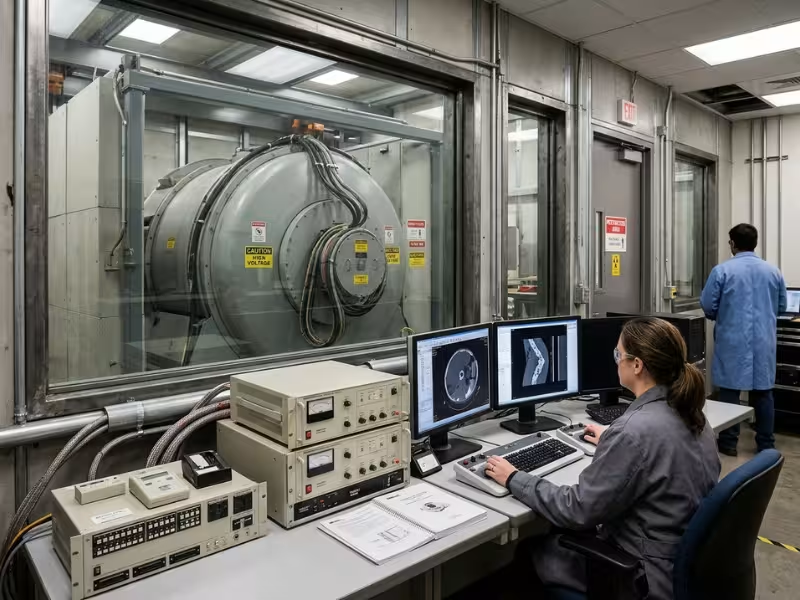
Two supplies rated to the same maximum voltage can deliver completely different results on the same application. The specs below are what actually distinguish them.
- Output voltage and current range: Choose a supply with headroom above your operating point. Running a supply at or near its rated limit continuously is the fastest way to shorten its life.
- Ripple: Listed as a percentage peak-to-peak of the output. Precision supplies reach 0.01% or lower. If your application involves imaging or detection, ripple is often the most important single specification.
- Stability and drift: How much the output shifts over time and with temperature changes, typically expressed in ppm per hour or ppm per °C. Long experiments and analytical instruments are most sensitive to this.
- Line and load regulation: Quantifies how well the output holds steady when input voltage or load impedance changes.
- Arc handling: How quickly the supply detects an arc event, limits fault energy, and restores normal operation. In applications like powder coating and electrostatic precipitation—where arcs happen constantly—this spec can outweigh ripple in importance.
- Efficiency and thermal management: Higher efficiency means less internal heat, and heat accelerates every failure mode. A supply with better efficiency often runs cooler, lasts longer, and costs less to operate.
- Control interface: Analog control (0–10 V or 4–20 mA), digital serial interfaces (RS-232, USB, Ethernet), or programmable setpoints affect how well the supply integrates into automated systems.
What Affects Reliability and Lifespan?
HV supplies don’t degrade like batteries. They fail through four distinct mechanisms, all of which can be managed through design choices and operating discipline.
- Insulation aging: Polymer insulation slowly loses dielectric strength under sustained electrical stress and elevated temperature. The rate roughly doubles for every 10°C increase in operating temperature—a well-known relationship in electrical engineering called the Arrhenius rule.
- Corona: Partial discharges—tiny, localized sparks at sharp edges or voids in insulation—erode material gradually and invisibly. Properly designed supplies use rounded geometry on all HV conductors and carefully controlled potting to eliminate sites where corona can start.
- Repeated arcing: Every arc event deposits energy in diodes, capacitors, and insulation. Supplies with fast arc detection and quenching circuits accumulate far less damage over time than those without.
- Heat: Accelerates all three mechanisms above. Adequate cooling, proper derating, and unobstructed airflow matter more over the long run than almost any other operating variable.
A supply running at 60% of its rated voltage in a temperature-controlled environment will almost always outlast one running at full rating in a warm cabinet.
High Voltage Safety: Risks and Protections
High voltage power supplies are engineered to be safe. The design protections in a well-built unit are extensive, and they work. What they can’t do is substitute for understanding—because the hazard profile of HV equipment differs from ordinary electronics in ways that aren’t obvious until someone explains them.
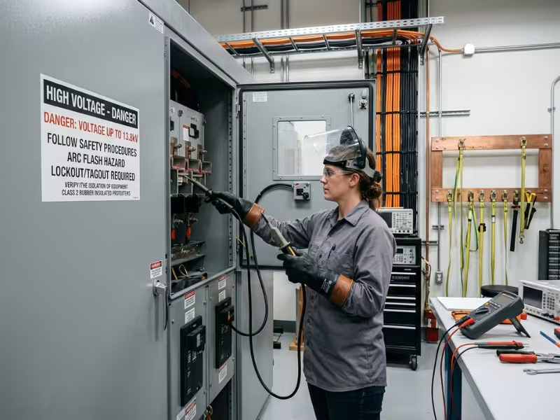
Why High Voltage Is Dangerous, Even at Low Current
Ohm’s law is the starting point. Your body has resistance, and voltage is what drives current through it. Dry skin at 120 V might produce a brief, unpleasant shock. High voltage breaks through skin resistance easily, pushing current deep into the body regardless of what the rated output current on the datasheet says.
Body-current effects, roughly:
- About 1 mA: A perceptible tingle
- About 10–20 mA: Involuntary muscle contraction—the “can’t let go” threshold
- About 50–100 mA crossing the chest: Sufficient to trigger ventricular fibrillation
Three additional hazards don’t require direct contact:
Stored charge. Output capacitors and long HV cables can hold a dangerous charge after the supply is switched off. The discharge time constant depends on load resistance; in some configurations, full voltage can persist for minutes without a dedicated bleed path.
Arcing. At sufficient voltage, an arc can bridge an air gap without physical contact, delivering burns, fire risk, and equipment damage. Keeping your hands away from the terminals is not sufficient if you’re within arc distance of an energized conductor.
X-radiation. In vacuum-tube and certain accelerator applications, electrons accelerated above roughly 15–20 kV can produce X-rays when they strike metal surfaces. This is not theoretical—it’s the basis of X-ray technology—and it’s why shielding requirements exist for equipment operating in that range.
Built-In Protections: Insulation, Grounding, and Interlocks
A properly designed HV supply layers multiple independent protections, so that failure of any single one doesn’t expose a user to unacceptable risk:
- Insulation, creepage, and clearance distances: Engineered gaps through air and across surfaces, calculated from the output voltage and applicable safety standards.
- Grounding: Provides a low-impedance path for fault current, preventing it from routing through a person.
- Interlocks: Shut down output the instant an enclosure is opened. These should never be bypassed.
- Bleeder resistors: Drain stored charge from output capacitors after shutdown, reducing the residual hazard window.
- Current limiting, overvoltage protection, and arc detection: Electronic protections that react in microseconds to milliseconds—fast enough to limit fault energy before damage propagates.
- Safety standard compliance: Standards such as IEC 61010-1 for laboratory equipment set minimum requirements for insulation, clearances, markings, and protective measures. Certifications (UL, CE) indicate that an independent body has verified compliance.
Safe Handling in Practice
The rules for working safely near HV equipment are not complicated, but they need to be followed without improvisation:
- Only trained, qualified people should work on or service HV equipment.
- Turn off power, apply lockout/tagout, and wait the full discharge time specified by the manufacturer.
- Verify zero voltage with a probe rated for the output voltage of the specific supply.
- Discharge output terminals with a grounding stick before touching any internal conductor.
- Keep one hand behind your back or in your pocket when probing near live circuits—the one-hand rule prevents current from crossing your chest if contact occurs.
- Never bypass interlocks, disable safety features, or operate with covers removed.
These protections reinforce each other. When one layer is removed—a bypassed interlock, a skipped discharge step, an unrated probe—the remaining layers carry a larger share of the risk than they were sized for. That’s when incidents happen.
Common Misconceptions About High Voltage Power Supplies
Most misunderstandings about HV equipment come from extending intuitions built on everyday electronics. The corrections below address the ones most likely to cause confusion—or worse.
Myth #1: Low current rating means it’s safe to touch
Fact: The rated output current governs steady-state delivery, not the instantaneous discharge energy from stored charge. Output capacitors and HV cables can release a pulse at current levels far exceeding the supply’s rated output. The current rating is a performance specification, not a safety one.
Myth #2: Once the supply is switched off, it’s safe
Fact: Capacitors and cables can hold dangerous charge levels for minutes after shutdown, particularly in configurations with high-impedance loads or no internal bleed resistance. Always verify with a rated probe and discharge before making contact.
Myth #3: High voltage equals high power
Fact: Power is voltage multiplied by current. A 30 kV supply delivering 1 mA produces 30 watts—about what you’d get from a small LED bulb. The voltage is extreme. The power is modest. These are independent quantities.
Myth #4: More voltage is always better
Fact: Excess voltage accelerates insulation aging, increases arc frequency, and can damage tubes, samples, and detector elements. The goal in selecting an HV supply is matching the application requirements precisely—not maximizing voltage headroom as a margin of safety.
High Voltage Power Supplies, Simplified
The complete picture reduces to a few fundamentals. Every high voltage power supply follows the same chain: rectify the input, switch it at high frequency, step up the voltage, rectify and filter the result, then regulate it continuously through feedback. That output is then applied to do one of three things: accelerate charged particles, generate strong electric fields, or stress gases and insulators for plasma generation or testing.
What makes HV engineering distinctive isn’t the voltage itself—it’s everything required to keep that voltage under control, from insulation design to arc recovery to the safety architecture surrounding the whole system.
If you’re evaluating a supply for a specific application, start by writing down four numbers: the required output voltage, the maximum current your load draws, the ripple tolerance your application can accept, and the polarity you need. With those in hand, most of the selection process becomes straightforward. If you’re sourcing the lower-voltage power stages that feed into or sit alongside HV systems—such as bias rails, control power, or interface electronics—Quankang’s full product range covers AC-DC solutions from 5 W to 1,000 W across medical, ITE, and custom configurations.