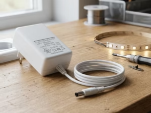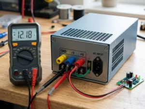
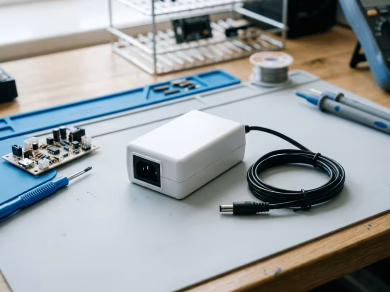
Most people use a switching mode power supply every day without thinking about it.
It sits inside a phone charger, a laptop adapter, an LED driver, or an industrial control box. It works quietly in the background. But when you need to choose one, the questions come fast.
Why is SMPS so common now? Why is it smaller than an old linear supply? When is it the better choice? And when can it create noise or EMI problems?
I deal with these questions often. Many buyers only look at voltage and current. That is not enough.
A good SMPS can save space, cut heat, and improve efficiency. A poor match can create ripple, heat stress, or control issues.
So before you pick one, it helps to understand what it really does and where it truly fits.
What a Switching Mode Power Supply Actually Is
A switching mode power supply is a circuit that converts and regulates electrical power by switching a transistor on and off at very high speed.
That switching happens thousands of times per second. The circuit takes power in one form, chops it up, then rebuilds it into the clean, steady voltage your device needs.
Here’s the key point people miss: SMPS is not a single part. You can’t point to one chip and call it “the SMPS.” It’s a complete system. A rectifier, a switching transistor, a transformer or inductor, an output filter, and a feedback loop all work together to do the job.
Three goals drive every good design.
First, efficiency. Instead of wasting extra energy as heat, the supply moves it through the circuit with very little loss. Most switching designs run at 85% to 95%.
Second, stable voltage. The feedback loop watches the output and adjusts on the fly. When your load jumps or the mains sags, the voltage holds steady.
Third, compact size. Because the transistor switches so fast, the transformer and capacitors shrink dramatically. That’s why a modern laptop charger fits in your palm.
So why does SMPS sit inside almost everything now? Because it solves the problems older supplies couldn’t. It runs cooler, weighs less, and handles a wide input range without a voltage switch.
That combination fits how we build electronics today. We want smaller devices, longer battery life, and less wasted power. A switching supply delivers all three at once.
That’s the real reason it took over.
How a Switching Mode Power Supply Works
Follow the power on its trip through the circuit, and the whole thing suddenly makes sense.
It starts with AC from the wall. The first stage rectifies that AC into rough DC. At this point the DC isn’t clean yet, but it doesn’t need to be. It’s just raw material for the next step.
Now comes the heart of the design. The switching transistor takes that DC and chops it into a high-frequency square wave, flipping on and off tens of thousands of times per second. This is where the “switching” in the name comes from, and it’s also the trick behind everything the supply does well.
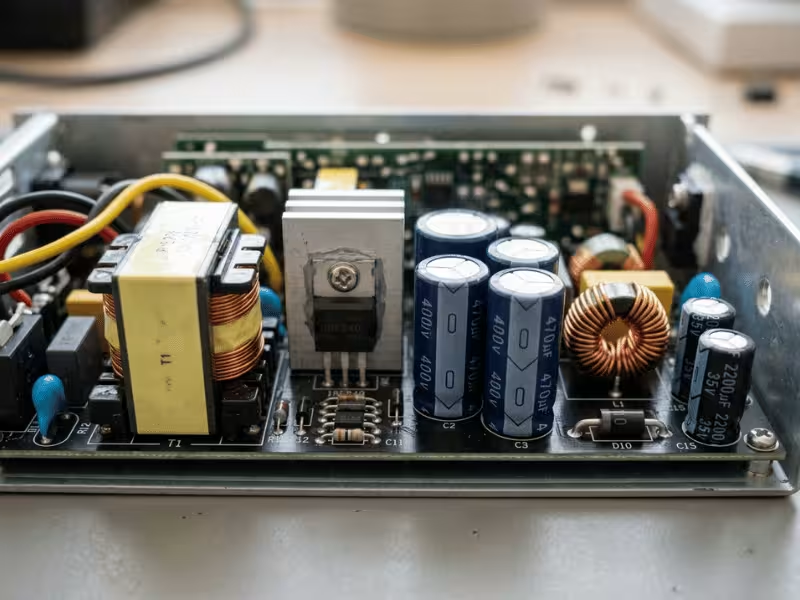
That fast switching feeds a transformer or inductor. During each pulse, the magnetic component stores a little energy, then hands it off to the output side. Because the switching happens so fast, this transformer can stay tiny. A slow 50/60 Hz linear design needs a heavy, bulky transformer to move the same power. Speed lets you shrink it.
Next, the output stage rectifies that high-frequency wave back into DC and filters it smooth. Capacitors soak up the choppiness and hand your device a steady voltage.
Finally, a feedback loop keeps watch. It samples the output, compares it to a target, and tells the transistor to switch a little longer or shorter. When your load jumps or the mains dips, this loop corrects it in an instant.
Stage | What happens |
|---|---|
Input rectifier | Turns AC into rough DC |
Switching transistor | Chops DC into a high-frequency wave |
Transformer/inductor | Stores and transfers energy in small bursts |
Output rectifier & filter | Rebuilds smooth, steady DC |
Feedback loop | Adjusts switching to hold voltage stable |
So why does this beat a linear supply? A linear design burns off extra voltage as heat, wasting it. A switching design barely touches the energy it passes — the transistor is either fully on or fully off, so very little gets lost. That’s where the high efficiency comes from, and why so little heat builds up.
The same fast switching that saves space and energy has a cost, though. Chopping current thousands of times per second creates ripple on the output and electrical noise that radiates out as EMI. Good design tames both, but they’re baked into how the supply works.
SMPS vs. Linear Power Supply
Now that you’ve seen how a switching supply moves power, the natural question follows: how does it stack up against the older linear design? The honest answer isn’t that one wins. Each one fits a different job.
Let me lay them side by side.
Factor | SMPS | Linear Power Supply |
|---|---|---|
Efficiency | 70–95%, wastes very little as heat | 30–60%, burns the extra voltage off |
Size and weight | Small and light, high-frequency magnetics shrink it | Bulky and heavy, needs a large 50/60 Hz transformer |
Heat output | Low, so it needs less cooling | High, often demands a big heatsink |
Noise and ripple | Switching ripple and EMI you have to filter | Very clean, quiet DC |
Complexity | More parts, magnetics, and EMI work | Simple to build and easy to troubleshoot |
Best fit | Compact, efficient, wide-input jobs | Low-noise analog, audio, RF, precision gear |
Efficiency is where SMPS pulls ahead. A switching supply passes most of its energy straight through, so a 90% design loses only a little. A linear supply throws away the voltage it doesn’t need, and that lost voltage turns into heat. On a high-current output, that waste adds up fast.
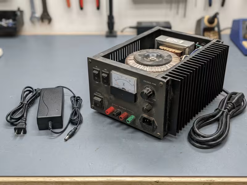
Size follows the same logic. Because a switching supply runs at high frequency, its transformer and capacitors stay tiny. A linear brick doing the same 12V at 5A carries a heavy transformer and often a chunky heatsink. Pick both up and you’ll feel the difference instantly.
Heat ties directly to efficiency. Less wasted energy means a cooler running supply and a smaller enclosure. Linear designs dump their extra energy as heat, which is why they so often hide behind large aluminum fins.
Now the trade-off flips. A linear supply gives you cleaner DC. It has no high-speed switching, so it produces almost no ripple and no EMI. A switching supply chops current thousands of times per second, and that leaves ripple on the output plus noise that radiates out. Good filtering tames it, but it never fully disappears.
Complexity matters too. A linear supply is simple. Fewer parts, easy to repair, forgiving to design. A switching supply demands careful magnetics, layout discipline, and EMI compliance work. That effort buys you efficiency and size, but it raises the bar.
So which one should you reach for?
Choose SMPS when space, weight, efficiency, or a wide input range drives the job — chargers, LED drivers, industrial supplies, anything battery-powered. Choose a linear supply when clean output beats everything else — sensitive analog front ends, low-noise audio, RF circuits, and precision instruments.
And in some designs, you don’t have to choose. A switching front end followed by a linear stage gives you both efficiency and a quiet final rail. That combination shows up often in gear that can’t tolerate noise but still needs the size and efficiency only switching can deliver.
Where Switching Mode Power Supplies Make the Most Sense
Some jobs practically demand a switching supply. The circuit runs on tight space, real efficiency targets, or a wide input range — and SMPS handles all three at once. Here’s where I reach for one first, and what to watch in each case.
Consumer chargers and adapters
Phone chargers and laptop bricks live and die on size and efficiency. An SMPS shrinks the whole thing to fit in your palm and keeps it cool in your bag.
The benefit is obvious: light weight, wide input, and low standby draw. The risk sits in cheap builds. A poorly filtered unit leaks EMI and sags under a full load, so verify the efficiency mark and real output rating before you trust it.
LED lighting
LED drivers need steady current, not just steady voltage. A switching design holds that current tight across a range of loads, which keeps the light even and the fixture efficient.
The payoff is less heat inside the fixture and a longer lifespan. Watch the ripple, though. Too much output ripple shows up as visible flicker, and that ruins otherwise good lighting.
Industrial control
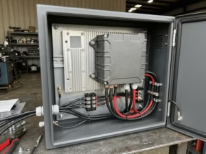
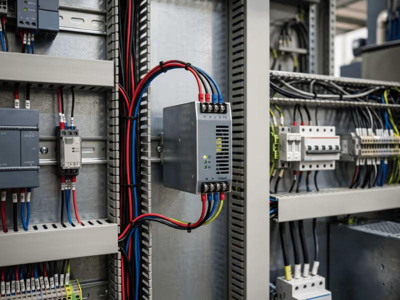
Control cabinets run hot, cramped, and around the clock. SMPS fits because it packs high power into a small DIN-rail footprint and tolerates a wide, noisy input.
You gain compact power and reliable regulation under swinging loads. The catch is the environment. Heat and vibration age components fast, so size for the cabinet temperature, not a lab bench at 25°C.
Telecom and networking
Routers, switches, and PoE gear pull steady current and often run nonstop. A switching supply delivers that efficiently and keeps enclosure heat down. For this kind of information technology equipment, a certified ITE power supply keeps the output clean and the safety marks in order.
The advantage is efficiency at scale — a few saved watts per unit adds up across a rack. The risk is load spikes. A loaded switch running PoE adapters draws hard, so leave real headroom or the rails dip when every port powers up.
Battery-powered electronics
Here every milliamp counts. A switching regulator squeezes maximum runtime from a cell by wasting almost nothing, something a linear part simply can’t match at these currents.
You get longer battery life and a wider usable voltage window as the cell drains. The trade-off is switching noise near sensitive analog or RF sections, which sometimes calls for a clean linear stage after the switcher.
Notice the thread running through all five. SMPS shines wherever efficiency, size, or input range drives the design. The one habit that saves you every time is the same — match the supply to the real load and the real environment, not just the label.
When an SMPS Is Not the Best Choice
A switching supply fits most jobs, but not every one. I’ve seen good designs held back because someone forced a switcher where a quieter supply belonged. Knowing when to walk away marks the difference between a decent design and a clean one.
The trouble almost always comes back to noise.
Very noise-sensitive analog circuits feel it first. A precision op-amp front end or a low-level sensor input can pick up the ripple and switching hash an SMPS puts out. That noise buries the small signals you care about, and no amount of gain fixes it.
RF front ends react even harder. Switching noise lands right in the bands your receiver listens to, raising the noise floor and killing sensitivity. A quiet linear rail keeps that floor low where it belongs.
Precision measurement gear tells the same story. When you’re chasing microvolts or clean references, switching ripple shows up directly in your readings. The supply itself becomes a source of error.
Some audio applications draw the line too. High-end preamps and low-noise stages can let switching artifacts leak into the sound, and careful ears catch it. A linear supply keeps the background silent.
So does that mean you drop SMPS entirely? Usually not.
The smarter move pairs them. Let a switching stage do the heavy lifting — handling the wide input and carrying most of the current efficiently. Then follow it with an LDO on the sensitive rail. The LDO scrubs off the leftover ripple and hands your circuit a clean, quiet output.
You keep the efficiency and small size of the switcher. You gain the clean rail your analog, RF, or audio section demands.
Match the supply to what the circuit truly needs. When clean output beats everything else, reach for a linear stage — even if it sits behind a switcher.
Common SMPS Topologies in Simple Terms
You don’t need to design a converter to shop for one. But recognizing the topology inside helps you understand what a supply does well and where it struggles.
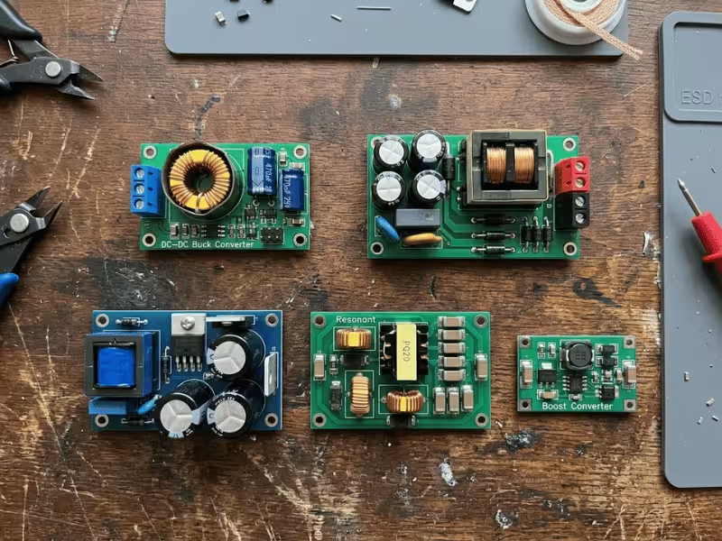
The first split is simple: isolated or not. An isolated design puts a transformer between input and output, which keeps mains voltage away from your device. A non-isolated design skips that barrier and just steps voltage up or down.
Here’s how the common ones break down.
Topology | Isolated or not | Typical use |
|---|---|---|
Buck | No | Steps voltage down close to the load — CPUs, DC-DC modules, point-of-load rails |
Boost | No | Steps voltage up — battery devices, LED strings, power factor front ends |
Buck-boost | No | Output above or below the input — battery gear as the cell drains |
Flyback | Yes | Low-to-mid power adapters, chargers, standby rails up to about 150W |
Forward | Yes | Mid-power supplies needing tighter regulation, roughly 100–300W |
Bridge-type (half/full) | Yes | High-power industrial and server supplies, hundreds of watts and up |
A few patterns are worth remembering.
Flyback dominates the low-to-mid range. When you pick up a phone charger or a small adapter, odds are a flyback sits inside. It’s cheap, compact, and isolated, which is exactly what those products need.
Bridge types take over at high power. Server supplies, big industrial units, and anything pushing hundreds of watts lean on half-bridge and full-bridge designs, because they move a lot of power without cooking the parts.
Non-isolated buck and boost converters live close to the load. They handle the DC-DC work on a board — dropping 12V down to what a chip wants, or pushing a battery’s voltage up to what a circuit needs.
Match the topology to the power level and isolation your job calls for, and the right supply gets a lot easier to spot.
What Causes SMPS Problems and Early Failures
Most switching supplies don’t fail because the design was wrong. They fail because something pushed them past their limits over time. Spot those pressures early, and you avoid the failure altogether.
Heat leads the list. High temperature ages every part inside, and it does the most damage to the electrolytic capacitors. As they heat and cycle, they dry out, their capacitance drops, and the output starts to sag or ripple. Age those caps enough and the whole supply gives up.
Airflow ties right into this. A supply crammed in a sealed box or blocked by dust bakes in its own heat. What ran fine on the bench dies early in a hot cabinet.
Surge stress hits from the other direction. A voltage spike on the input can punch through the switching transistor or overwhelm an undersized fuse or MOV. One bad surge ends the unit on the spot.
Overload wears it down slower. Run a supply at its absolute rating all day and it never gets a break. The parts stay hot, the margins vanish, and the lifespan shrinks.
Marginal design and cheap components make all of this worse. A supply built with bottom-tier caps or thin safety margins looks fine at first, then fails months later — usually behind a wall or inside a machine, where it costs the most to fix.
How to cut the failure risk
You can head off nearly all of this before you buy or install.
- Leave headroom. Run the supply at 70–80% of its rating, never the limit.
- Respect the derating curve. Size for the real ambient temperature, not 25°C.
- Keep air moving. Give it clearance, keep vents clear, and clean out dust.
- Guard the input. Confirm proper surge protection for your environment.
- Buy quality caps. Look for reputable brands and rated lifespans, not just a low price.
Match the supply to the real load and the real conditions, and it will outlast the equipment around it.
How to Choose the Right Switching Mode Power Supply
This is where the theory pays off. A good pick starts with the load and ends with the enclosure, and skipping a step here shows up later as heat, noise, or a supply that quits early. I work through the same order every time.
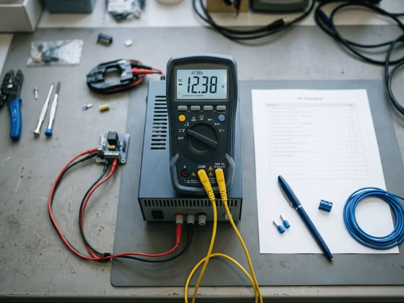
Start with voltage and current. Match the output voltage to what your device needs, then add up the current every part on the rail will pull. Don’t size to the bare minimum. Leave 20–30% headroom above your steady draw. A supply running flat out stays hot and dies young, and it has nothing left when a load spikes.
Check the input range next. Read the supply’s input spec against your real source. If it powers gear across regions, look for a wide range that covers 100–240V without a switch. On a DC input, confirm the supply tolerates the low and high ends your source actually swings to, not just the nominal value.
Then look at ripple and transient response. Every switcher leaves some ripple on the output. The question is whether your load can live with it. Digital gear usually shrugs it off. Sensitive analog, audio, or RF sections won’t. Check the transient spec too — when your load jumps, how fast and how far does the output dip before it recovers? A slow loop starves the load at the worst moment.
Confirm isolation and safety approvals. Decide whether your design needs an isolated output that keeps mains away from the user. Then verify the marks match your target market — the right certifications, not a vague logo. An unapproved supply fails inspection and puts users at risk.
Read the efficiency at your real operating point. Datasheets love to print peak efficiency, but you rarely run there. If a supply hits 94% at full load and you use it at 30%, that headline number means little. Find the efficiency curve and read it where your load actually sits.
Review thermal derating and airflow. A supply rated at 25°C delivers far less inside a warm cabinet. Pull the derating curve and size for your real ambient temperature. Then plan the airflow — give the unit clearance, keep vents clear, and never bury it in a sealed box that traps its own heat.
Finish with the physical fit. Match the connector, polarity, and mounting to your design. A DIN-rail unit, an open-frame board, and a sealed brick each suit a different job. When no standard unit matches your voltage, connector, or footprint, custom power adapters let you spec the exact output and form factor your design needs. Confirm it drops into your enclosure and the wiring compartment fits your conductors before you commit.
Selection factor | What to check | Why it matters |
|---|---|---|
Voltage and current | Exact output voltage, total load current, 20–30% headroom | Undersizing overheats the supply and leaves nothing for spikes |
Input range | Real source range, wide-input mark for global use | An out-of-range input trips the supply or shortens its life |
Ripple and transient | Output ripple spec, dip and recovery under load steps | A noisy or slow rail disrupts sensitive and fast-changing loads |
Isolation and approvals | Isolated output if needed, marks for your market | Missing approvals fail inspection and endanger users |
Efficiency at your point | Efficiency curve read at your actual load, not peak | Real losses drive real heat and running cost |
Thermal derating | Derating curve for your ambient, clear airflow | A hot enclosure quietly strips away rated output |
Connector and form factor | Connector, polarity, mounting style, footprint | The wrong fit blocks the install or damages the device |
Run these seven in order, and the field narrows fast. You’ll drop the units that look fine on the label but fail in the real load, the real cabinet, and the real environment where the supply has to live.
The habit that saves the most trouble is simple: never trust the headline spec alone. Read the curves, check the marks, and size for where the supply will actually run.
Frequently Asked Questions
What does SMPS stand for?
SMPS stands for switching mode power supply. The name points to how it works: it switches a transistor on and off at high speed to convert and regulate power. Some people write it as switched-mode power supply, but they mean the same thing.
How is SMPS different from a linear power supply?
A switching supply passes most of its energy straight through, so it runs efficient, cool, and small. A linear supply burns off the extra voltage as heat, which makes it bigger and warmer. The trade-off? Linear gives you cleaner, quieter output. SMPS wins on size and efficiency.
Why does SMPS create EMI?
It comes from the switching itself. The transistor chops current thousands of times per second, and those fast edges throw off electrical noise. That noise radiates out as EMI. Good filtering and careful layout tame it, but it never fully goes away.
Can I use SMPS for audio circuits?
You can, but pick carefully. Switching ripple can leak into sensitive audio stages and add hiss or hum you’ll hear. For low-noise preamps, I run a switcher up front, then add an LDO on the audio rail. That combo keeps the efficiency and hands the audio section a clean, quiet supply.
What is typical SMPS efficiency?
Most designs land between 85% and 95%. Cheaper or older units sit lower, near 70–80%. Just remember the datasheet often prints peak efficiency. Read the curve at your real load, since a supply at 30% draw performs differently than one running full out.
How do I choose between isolated and non-isolated designs?
Ask whether mains voltage must stay away from the user or the output. If yes, go isolated — a transformer sits between input and output. For board-level DC-DC work, where you’re just stepping voltage up or down safely, non-isolated is smaller and cheaper.
The Bottom Line
A switching mode power supply earns its place three ways: efficiency, compact size, and voltage that holds steady under changing loads.
But it isn’t the right answer everywhere. Chop current that fast and you invite ripple and EMI, which some circuits simply won’t tolerate.
So the choice never comes down to the headline spec. It comes down to your load, how much noise your circuit can live with, the heat where it runs, whether you need isolation, and the safety marks your market demands.
Here’s your next move. Write down your real load list, the actual ambient temperature, and the certifications you need. Then read the supply’s curves against those numbers.
Match it to where the supply truly lives, and it’ll serve you for years. Which factor will you check first — the load, the heat, or the marks on the label?