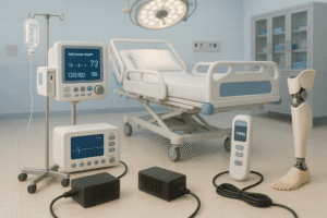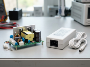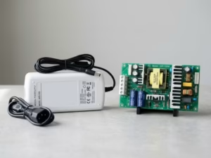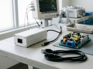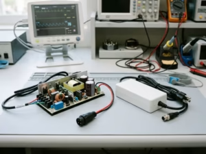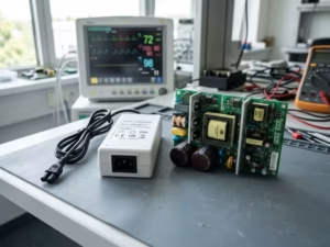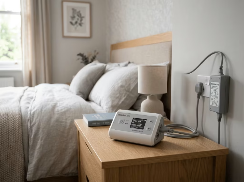
A ventilator that once lived in an ICU now sits on a bedside table in a house built in 1955, plugged into an outlet with no reliable ground, run by a patient’s spouse who has never opened a technical manual. That single change of setting is what separates home healthcare device safety standards from clinical ones — and it is why IEC 60601-1-11 exists. The standard is a collateral document that works alongside IEC 60601-1 to add the requirements a device needs once it leaves the hospital and runs in an uncontrolled home by an untrained user. For power supply design, that shift rewrites several rules you cannot carry over unchanged.
What follows works through the part that actually decides your bill of materials: which devices fall under the standard, how it stacks on top of IEC 60601-1, why Class II input becomes the default, and how each requirement lands on the supply you select.
What Counts as a Home Healthcare Environment Under IEC 60601-1-11?
If your device is meant to run outside a professional healthcare facility, it almost certainly falls under IEC 60601-1-11. The standard is scoped by where the device is used and who uses it — not by what it does clinically.
Which Locations and Users Trigger the Standard?
The home healthcare environment is any place that is not a professional healthcare facility, where a patient lives or receives care. Private homes are the obvious case, but the scope also reaches schools, vehicles in transit, and other non-clinical settings. The device does not have to be permanently installed or tied to facility infrastructure. Once a lay person is expected to operate it in one of those places, the collateral standard applies.
One boundary case is worth flagging before you assume anything: a device installed by trained personnel in a home may sit outside the strict input rules, because the installer controls the electrical connection. Read the intended-use statement carefully — that exemption disappears the moment the patient can unplug and move the unit.
Why Does an Uncontrolled Environment Rewrite the Requirements?
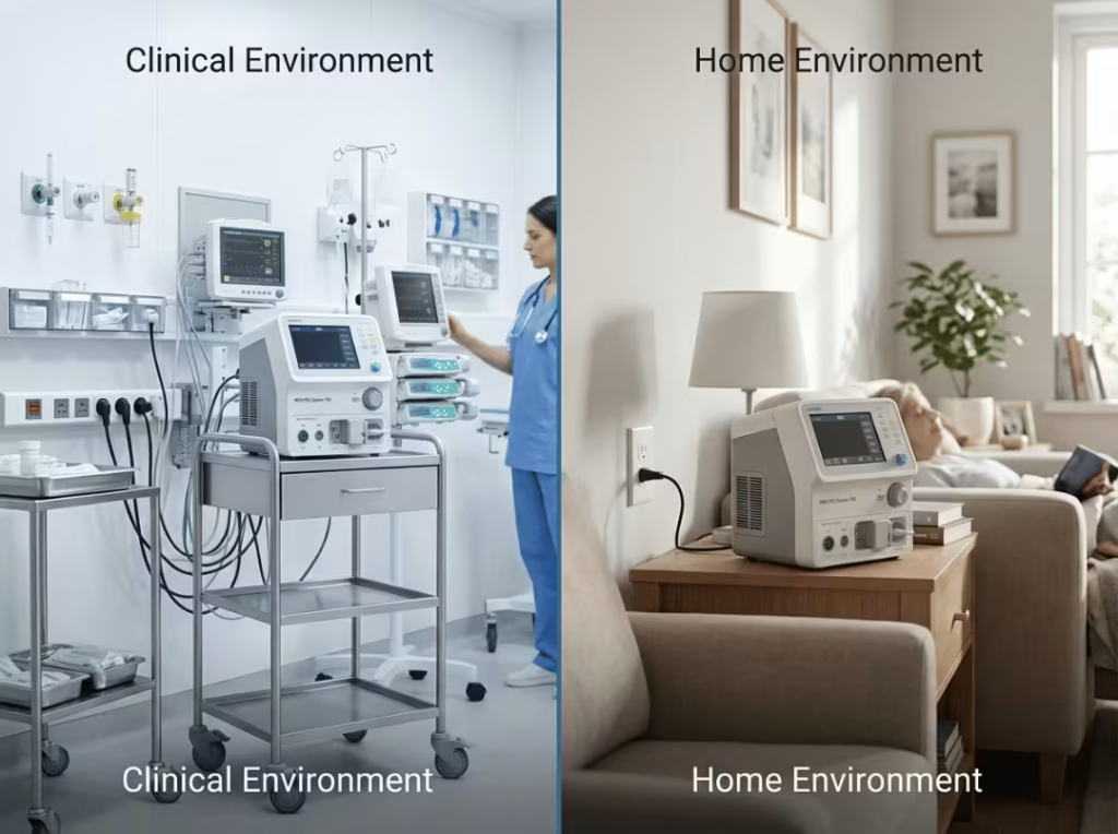
An uncontrolled environment strips away the assumptions a clinical design leans on. In a hospital, mains voltage is stable, protective earth is reliable, temperature and humidity stay in range, and trained staff step in when something goes wrong. None of that survives the trip home.
Mains can sag, brown out, or drop entirely. The outlet may carry no functional earth. The unit may end up in a bathroom, on a windowsill, or on a floor that gets vacuumed weekly. Each condition forces a specific demand onto the supply — wider input tolerance, insulation that does not depend on grounding, ingress protection you would never bother specifying for a benchtop clinical box.
Who Is the “Lay Operator,” and Why Does It Change Your Design?
A lay operator is anyone running the device without medical or technical training — usually the patient or a family caregiver. This matters because the standard assumes that person will make the mistakes a clinician never would, and your design has to absorb those mistakes rather than rely on the user avoiding them.
They will push a connector into the wrong port, skip the warning label, run the device with wet hands, or leave it going unattended overnight. Three questions settle whether you are in scope:
- Is the device used outside a professional healthcare facility?
- Is it operated by a patient or lay caregiver rather than trained staff?
- Is it non-permanently installed, so the user controls the mains connection?
Answer yes to these, and you design to the collateral standard from the first schematic — not after a failed pre-scan.
How Does IEC 60601-1-11 Differ From IEC 60601-1?
IEC 60601-1-11 does not replace IEC 60601-1; it stacks on top of it. You meet every provision of the general standard, then satisfy the extra home-environment requirements as well. Treating the collateral standard as a substitute is the most common and most expensive misreading in home-device programs.
IEC 60601-1 is the general safety standard for all medical electrical equipment, written around clinical use by trained professionals. IEC 60601-1-11 references and extends it for one specific context — the home. It tightens input class, widens the input voltage range, raises immunity expectations, and adds mechanical and misuse provisions the general standard barely touches. For the underlying detail on the base your home design builds on, this breakdown of IEC 60601-1 safety standards for power supplies covers the general framework in depth.
Factor | IEC 60601-1 (General) | IEC 60601-1-11 (Home Collateral) |
|---|---|---|
Intended environment | Professional clinical facility | Uncontrolled home / non-clinical setting |
Assumed operator | Trained medical staff | Lay operator (patient or caregiver) |
Protective earth | Can rely on facility grounding | Cannot assume reliable earth — Class II or internal power |
Input voltage range | Nominal range | Must operate down to ~80–85% of nominal |
EMC immunity | Clinical baseline | Higher immunity to nearby consumer electronics |
Mechanical / ingress | Limited emphasis | Drop, ingress (IP), and robustness provisions |
Misuse protection | Assumes competent operator | Must design against lay-user error |
The practical fallout: a supply that cleared a hospital device program can be disqualified for the home version on input class or leakage alone. Requalify against the collateral standard rather than carrying the clinical result forward and hoping it holds.
Why Do Home Medical Devices Usually Require Class II Power Input?
For a non-permanently-installed home device, Class II input or internal power is effectively mandatory, because you cannot trust the home’s protective earth. This is the first filter in any home power supply selection, and it removes a large slice of clinical designs on contact.
What Makes Protective Earth Unreliable at Home?
Class I safety leans on a protective earth connection to carry fault current away. In the home, that assumption breaks down. A large share of homes across the US and Europe predate grounded wiring, and even where a ground pin exists, its integrity is unknown and untestable by the person plugging in the device.
The standard answers this by requiring that home devices not permanently installed by licensed personnel use Class II AC input or run on internal power. You cannot engineer around a safety earth that may simply not be there.
How Does Class II Deliver Safety Without a Ground?
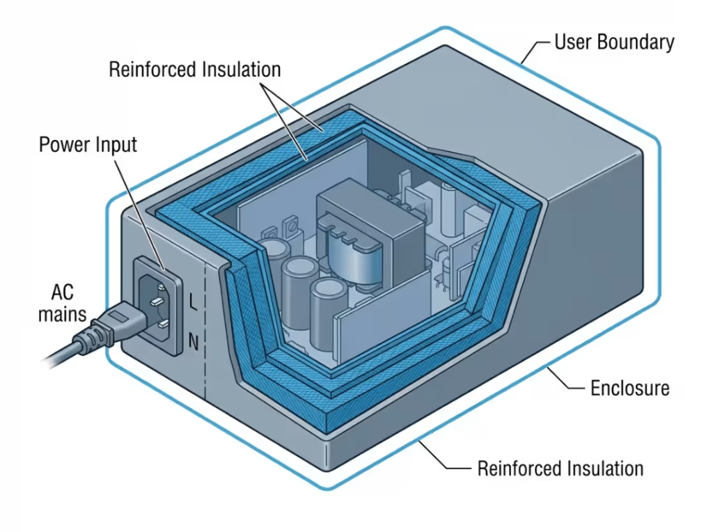
Class II protects through construction rather than grounding. Where a Class I design relies on protective earth, a Class II design places two layers of basic insulation, or a single layer of reinforced insulation, between the user and any live conductor.
That insulation barrier does the job the ground connection would have done. It also moves your design attention onto insulation coordination — creepage, clearance, and dielectric strength become the primary line of protection instead of a backup to earth, so they carry more weight in your candidate evaluation.
What Does the Class II Requirement Rule Out?
Any supply that needs a functional earth to meet its safety or leakage numbers is out for a non-installed home device. That is the blunt version.
The recurring mistake is carrying a Class I hospital power scheme into a home variant to save a redesign, then finding during certification that the leakage figures only hold with earth connected. Fix the path at the architecture stage: specify Class II or internally powered from the first decision, and treat any Class I candidate as viable only for permanently installed equipment.
Which Power Supply Requirements Matter Most for Home Devices?
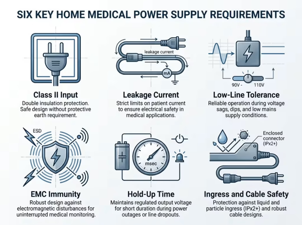
Six characteristics carry most of the compliance weight, but they do not carry it equally. Sort them into hard gates that disqualify a supply outright, high-risk items that decide whether you pass field conditions, and easily underestimated items that surface only after months in use. Working in that order keeps you from optimizing a spec that a hard gate was about to eliminate anyway.
Hard Gates: The Requirements That Disqualify a Supply Outright
Three requirements decide eligibility before anything else, so apply them first and drop any candidate that misses.
Class II or internal power. Covered above — a non-installed home device cannot depend on protective earth, so a supply that needs one is out.
Leakage current by applied-part class. Your applied-part class sets the ceiling, and that ceiling shrinks the candidate list faster than any other spec. Type BF permits higher patient leakage than Type CF; CF, used for direct cardiac contact, holds patient leakage to roughly 10 µA under normal conditions. This collides head-on with EMC design — larger Y-capacitors sharpen immunity and emissions but raise leakage, so a supply tuned for a CF home device has to reconcile the two rather than optimize either. Confirm the leakage figures against your class before you look at anything else; a supply that is fine for BF can be disqualified outright for CF.
Wider input voltage tolerance. The supply must keep the device functional at reduced mains, typically down to 80–85% of nominal depending on the application. Home outlets sag and brown out in ways clinical circuits rarely do, and a life-supporting device cannot drop out because the voltage dipped. Verify the supply holds regulation and full rated output across the extended low-line range, not just at nominal — a narrow-window supply may technically run while quietly losing headroom at the bottom.
High-Risk Items: The Requirements That Decide Field Performance
These will not always block certification, but they are where home devices fail in a customer’s living room rather than on your bench.
EMC immunity in a noisy environment. Home devices need more immunity than clinical ones, because the electromagnetic environment is dirtier and unmanaged. A hospital controls what runs near sensitive equipment; a living room does not, and microwaves, routers, cordless phones, and cheap switching adapters all share the outlet strip. Build in comfortable immunity margin and expect to defend both emissions and immunity under the home provisions of the EMC requirements — margin here is insurance against a failure that only appears off-site.
Power interruption and hold-up time. For life-supporting devices, the supply has to ride through short interruptions and give the system time to hand over to a backup source. A momentary outage cannot be allowed to reset or halt a device keeping someone alive. Longer hold-up time buys the milliseconds the system needs to detect loss of mains and switch to battery, so plan backup power and bidirectional communication between supply and controller for an orderly handover. For non-critical devices, a clean restart may be acceptable — let the clinical consequence of an interruption set that call, not convenience.
Easily Underestimated Items: The Requirements That Surface Late
These rarely appear in early spec debates, yet they drive a disproportionate share of field returns.
Mechanical robustness, ingress, and cable safety. Home devices get dropped, splashed, and handled by people who are not being careful. Match the IP rating to the realistic worst case — a nebulizer beside a sink is a different environment from a monitor on a shelf — and specify cabling that survives daily unplugging. Under-specifying ingress is a quiet failure mode that only shows months into service, and it feeds directly into useful life. This is where the gap between MTBF vs lifetime turns practical: a home unit runs for years with almost no maintenance, so a strong MTBF figure means little if the supply’s real service life is short under home conditions.
Labeling and misuse prevention at the supply level. Where a lay user can touch, connect, or misuse the power interface, prevent the error physically rather than warn against it. Keyed connectors, protected interfaces, and mating that only works one way beat any label. Assume the warning gets ignored and the connector gets forced — then design so nothing unsafe follows when it does.
Which Use Risks Must You Design Against for Lay Users?
The home introduces failure paths a clinical design never has to consider, and the usability engineering process has to name them explicitly. The mental shift is from “assume a competent operator” to “assume the operator will get it wrong,” and every countermeasure flows from there.
How Do You Prevent Misconnection and Wrong-Mode Operation?
Design so a lay user physically cannot connect the wrong thing to the wrong port, and cannot land in an unsafe mode without noticing. A nurse spots a misconnection; a spouse at 2 a.m. does not.
Use keyed, visually distinct connectors so incorrect mating is impossible rather than merely discouraged, and make the active operating mode unmistakable. Ambiguity about whether a device is running, charging, or off becomes a real hazard the moment the person watching has no training to fall back on.
How Do You Handle Movement, Environmental, and Biological Exposure?
Assume the device gets moved while running, exposed to moisture and temperature swings, and contaminated by biological material. A home unit does not stay on a stable, clean bench.
Build for it: secure cabling that tolerates being yanked, an enclosure that handles the full temperature and humidity range in the standard, and surfaces that clean without breaking the seal. Each of these traces back to a power or enclosure decision made early — not a warning added late in the documentation.
How Do You Engineer Out Physical Hazards to Vulnerable Users?
Where children or vulnerable users share the space, physical hazards from the device itself have to be designed out — a point the general standard barely raises and the home standard makes explicit.
Cables long enough to strangle, small detachable parts that can be swallowed or inhaled, and accessible components that invite tampering all need attention. The fix is mechanical almost every time: captive parts, managed cable length, enclosures that resist casual opening. Instruction alone does not clear this requirement.
How Do You Choose a Power Supply for a Home Healthcare Device?
Selection runs in a fixed order, because each step narrows the field for the next. Jumping ahead — picking a supply on size or price before the class and leakage ceiling are locked — is exactly how programs end up requalifying late and expensively.
Step 1 — Classify the device and use environment. Confirm the device falls under IEC 60601-1-11 and document the intended environment and operator. This decision drives every requirement downstream, so settle it before any electrical work begins.
Step 2 — Confirm applied-part type and leakage ceiling. Establish whether the device is Type BF or CF, then fix the leakage limit that class demands. This eliminates the most candidates, so apply it early rather than discovering it late.
Step 3 — Lock Class II or internally powered. For a non-installed home device, rule out any supply that needs a functional earth. Anything requiring protective earth stays viable only for permanently installed equipment.
Step 4 — Verify 2 × MOPP where the supply touches the patient path. If the supply sits in the patient-contact path, confirm two means of patient protection — roughly 8 mm creepage and 4000 VAC dielectric withstand for a 2 × MOPP barrier. Designing to 2 × MOPP also simplifies the certification argument across multiple markets.
Step 5 — Check EMC immunity and mains-disturbance behavior. Confirm comfortable immunity margin and predictable behavior under low-line and transient mains conditions. Test at the bottom of the input range, not just at nominal, since that is where home outlets actually operate.
Step 6 — Plan for power interruption. For life-supporting devices, specify hold-up time and a backup strategy, and confirm the supply can coordinate a clean handover to battery. For non-critical devices, decide whether a restart is acceptable based on clinical consequence.
Step 7 — Confirm documentation and certification support. Verify the supplier provides IEC 60601-1 and 60601-1-11 test reports, CB scheme documentation, and integration support. A supply without complete documentation cannot carry your certification, however strong the hardware. Where no standard supply fits the home constraints at once, weigh a custom path — the custom medical power supplies considerations are worth reviewing before you commit the NRE.
Which Home Devices Need Different Power Priorities?
The requirements reorder themselves by device, because clinical consequence and physical environment differ. Matching your device to the right priority set is faster than treating every home product the same — and it is where teams most often misallocate their design effort.
CPAP and Sleep Therapy Devices
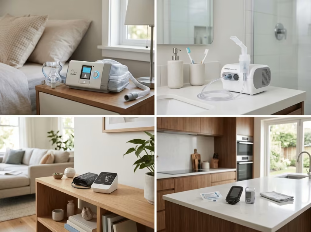
Acoustic quiet, continuous-duty durability, and interruption behavior lead here, because the unit runs all night beside a sleeping person’s head, untouched, for years. A supply that hums or restarts with an alarm defeats the product before any spec sheet matters.
Prioritize silent operation, tolerance for continuous duty without thermal stress, and a graceful response to a brief mains interruption. Long service life outweighs peak performance, since the device is expected to work unattended night after night with no maintenance.
Nebulizers and Respiratory Devices
Wide input tolerance and mechanical ruggedness come first, because nebulizers get handled roughly, used near water, and often run on marginal outlets in older homes. The failure mode here is physical and environmental, not clinical subtlety.
Specify a supply that holds output across the extended low-line range and an enclosure with ingress protection suited to a humid, splash-prone setting. These devices trade sophistication for the plain ability to survive real-world handling.
Home Patient Monitors
Low leakage current, applied-part class, and EMC immunity dominate, because the monitor connects to the patient and sits among household electronics. A monitor with BF or CF applied parts inherits a strict leakage ceiling that shapes the entire power design from the outset.
Prioritize a low-leakage supply matched to the applied-part class and an EMC design with margin to reject interference from nearby consumer devices. Accurate readings under a noisy environment are the whole point of the device.
Portable Diagnostic and Infusion Devices
Size, reliability, and backup power get weighed together, because these units travel with the patient yet cannot stop mid-function. An infusion pump halting mid-delivery is a clinical event; a diagnostic reader restarting is not.
Balance a compact form factor against the hold-up time and backup capability the clinical function demands. For an infusion device, interruption behavior is non-negotiable; for a simple reader, a restart may be tolerable — let the clinical stakes rank the priorities.
FAQ
What is IEC 60601-1-11?
IEC 60601-1-11 is a collateral standard used alongside IEC 60601-1 to define safety and performance requirements for medical electrical equipment used in the home. It adds provisions for uncontrolled settings, lay operators, unreliable mains, and mechanical robustness that the general standard does not fully address.
Is IEC 60601-1 enough for a home-use device?
No. IEC 60601-1 is the general standard, but a home-use device must also meet IEC 60601-1-11 on top of it. The collateral standard adds Class II input, wider voltage tolerance, higher immunity, and misuse protection that a design meeting only 60601-1 will typically fail to satisfy.
Why is Class II preferred for home healthcare equipment?
Because the home’s protective earth cannot be trusted. Many homes lack reliable grounding, so IEC 60601-1-11 requires non-permanently-installed devices to use Class II input or internal power. Class II achieves safety through double or reinforced insulation rather than a ground connection, removing dependence on an earth that may not exist.
Do home-use medical devices need backup power?
Life-supporting devices do. IEC 60601-1-11 expects such equipment to keep running through a mains interruption until an alternative supply takes over. Longer hold-up time and bidirectional communication between supply and controller enable an orderly handover. Non-critical devices may tolerate a clean restart, depending on the clinical consequence.
What’s the difference between BF and CF applied parts?
Type BF and Type CF are applied-part classifications that set patient leakage limits. BF permits higher leakage and suits parts in body contact but not the heart. CF is the strictest, intended for direct cardiac contact, holding patient leakage to roughly 10 µA in normal condition. CF-rated devices demand tighter supply leakage control.
How does home EMC differ from hospital EMC?
Home EMC demands higher immunity because the environment is unmanaged. A hospital controls what operates near sensitive equipment; a home does not, exposing the device to microwaves, routers, cordless phones, and low-quality adapters. IEC 60601-1-11 raises immunity expectations accordingly, so home devices need more EMC margin than clinical equivalents.
Getting the Compliance Path Right
Three decisions carry most of the outcome. Confirm early whether the device falls under IEC 60601-1-11, because that answer changes input class and immunity rules before you draw a schematic. Fix the applied-part class and its leakage ceiling next, then lock Class II or internal power. Finally, plan for mains interruption and home-grade EMC as first-order requirements rather than afterthoughts.
One boundary bears repeating: a supply pre-certified to IEC 60601-1 and 60601-1-11 removes a large block of test risk, but it certifies the supply, not your finished device. Your enclosure, grounding, cabling, and layout still decide the final result, and the complete device needs its own testing.
If you are specifying a supply now:
- Download the home healthcare PSU compliance checklist to work every requirement above against your candidates.
- Talk to a power engineer about your device class and applied-part type before you shortlist.
- Request an IEC 60601-1-11 pre-compliance review to catch input-class, leakage, and immunity gaps while they are still cheap to fix.