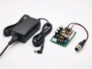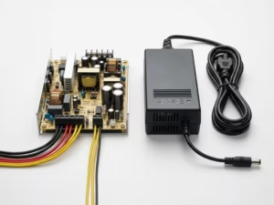
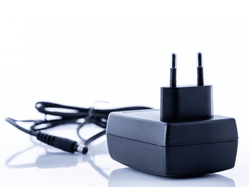
A 5V DC power supply converts electrical power into a steady 5-volt direct current output that low-voltage electronics need to run safely and reliably. You will find it behind USB chargers, development boards, sensors, smart home devices, LED modules, and many embedded control systems. Because 5V is built into the USB standard and matches the operating voltage of countless digital circuits, it has become one of the most common power choices in both consumer and professional electronics. This guide explains what a 5V DC power supply is, what “5V DC” actually means, how the internal components work together, and which specifications matter when you compare options.
What Is a 5V DC Power Supply?
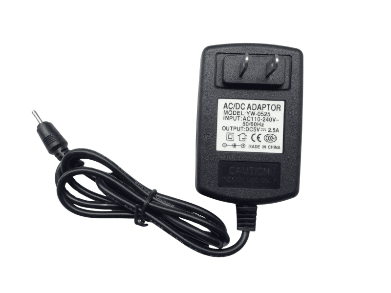
A 5V DC power supply delivers a regulated 5-volt direct-current output to power electronic equipment. Its main job is to take energy from a source that devices can’t use directly and turn it into a stable, low-voltage supply they can.
In most cases, the input comes from a wall outlet. That means 100–120V AC in North America or 220–240V AC in Europe and much of Asia. The power supply steps this high-voltage alternating current down, converts it to direct current, and regulates it to hold a steady 5V. Some 5V supplies start from a DC source instead, such as a 12V vehicle system, a lithium battery pack, or a solar panel. In those cases, a DC-DC converter changes one DC voltage to another.
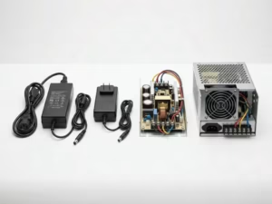
5V power supplies come in several physical forms:
- USB wall adapters with USB-A or USB-C ports
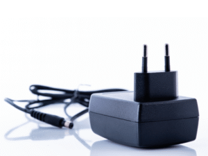
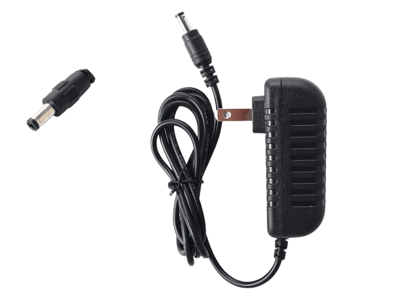
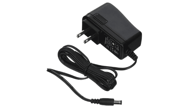
- Plug-in adapters with a fixed cable and barrel connector
- Desktop adapters with a separate AC power cord
- Enclosed switching supplies with screw terminals for fixed installations
- Open-frame modules built into larger equipment
- Power banks and battery modules with 5V USB output
Output current varies widely by design. A small USB adapter for a sensor or accessory may supply only 500 mA to 1A. A single-board computer usually needs 2.5A to 5A. An enclosed industrial 5V supply that feeds addressable LED strips or multiple control boards can deliver 20A, 40A, or more.
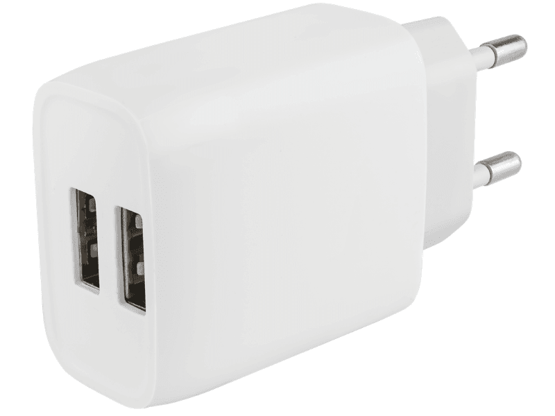
Common uses include USB-powered accessories, microcontroller boards, Raspberry Pi systems, IoT gateways, point-of-sale terminals, small displays, networking modules, and embedded controllers. Most modern designs also include protection features that shut down or limit output when something goes wrong. These typically cover overvoltage, overcurrent, short circuits, and overheating.
What Does 5V DC Mean?
The label “5V DC” appears on adapters, device housings, and product manuals. It tells you two things about the power, and each one affects compatibility.
“5V” Is the Output Voltage
The “5V” refers to the voltage the power supply delivers, measured in volts. You can think of voltage as the electrical pressure that pushes current through a circuit. A device rated for 5V input is designed to work within a narrow window around that value. The USB 2.0 specification, for example, allows roughly 4.75V to 5.25V at the port.
“DC” Means Direct Current
“DC” stands for direct current, which means the electricity flows in one direction only. This differs from the alternating current (AC) in household outlets, which reverses direction 50 or 60 times per second. Digital chips, sensors, and microcontrollers all need DC power, which is why a power supply is required between the wall outlet and the device.
Why the Voltage Must Match
Voltage is the one value you should never guess. If you connect a 5V device to a 9V or 12V supply, the excess voltage can destroy chips, regulators, and other components almost instantly. A supply that falls noticeably below 5V causes different problems. Microcontrollers may reset, USB devices may disconnect, and boards like the Raspberry Pi may throttle performance or show low-voltage warnings.
Why the Current Rating Can Be Higher
Current works differently. A device draws only the current it needs, and the power supply does not force extra current into it. That means a 5V 3A supply can safely power a device that needs only 5V 1A. The reverse is where trouble starts. A 5V 1A supply connected to a device that needs 2A will struggle, overheat, or let its output voltage sag under load.
A simple rule covers most situations: match the voltage exactly, and choose a current rating equal to or higher than the device requirement.
Why Polarity Matters for Non-USB Devices
USB connectors are keyed, so positive and negative always land in the right place. Barrel connectors, screw terminals, JST plugs, and bare wires offer no such guarantee. Many barrel-jack devices use a center-positive layout, but not all of them do. Always check the polarity symbol on the device or datasheet before connecting. Reversed polarity can damage a circuit even at a voltage as low as 5V.
Why Is 5V DC Power So Widely Used?
5V was not chosen at random. Several practical and historical factors turned it into a default voltage for low-power electronics.
Safety. 5V falls well within the safety extra-low voltage (SELV) range. You generally can’t feel a shock from a 5V source, which makes it suitable for handheld products, desktop gear, classrooms, and hobby projects. Short circuits can still cause heat and damage, but the risk to people is very low.
USB standardization. USB defined 5V as its base power voltage from the start. Billions of ports, chargers, and cables now share that voltage. Even USB-C Power Delivery, which can negotiate higher voltages, starts every connection at 5V. That makes 5V the one voltage almost any USB power source can supply.
Compatibility with digital electronics. Early TTL logic circuits ran on 5V, and that legacy shaped decades of component design. Many microcontrollers, sensor modules, relay boards, displays, and communication modules still accept 5V directly or include onboard regulators designed around a 5V input.
Broad adoption and low cost. Because so many products use 5V, adapters, cables, connectors, and converter modules are easy to find and inexpensive. Designers can pick from a large supply chain, and end users can often replace a lost adapter without special ordering.
Efficient conversion. Modern switching regulators convert mains power or higher DC voltages to 5V with little waste. This lets product designers build small, cool-running adapters and power devices from batteries, vehicle systems, or industrial 24V rails without large efficiency losses.
Main Components of a 5V DC Power Supply
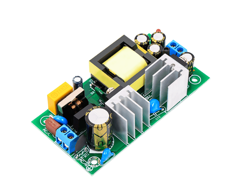
A 5V DC power supply uses several components that work together to turn raw input power into a clean, stable 5V output. The exact layout depends on whether the unit is a linear design or a switching mode power supply (SMPS). Most modern 5V supplies use SMPS designs, but both share the core building blocks below.
Input Circuit
The input stage receives power from the AC mains or another source. It usually includes a fuse to guard against catastrophic faults, an EMI filter to block electrical noise from traveling in or out, and surge protection parts such as a varistor to absorb voltage spikes.
Transformer
In a linear supply, a large transformer steps mains voltage down to a low AC voltage suited to a 5V output. In a switching supply, the transformer operates at tens or hundreds of kilohertz rather than 50/60 Hz. Higher frequency allows a much smaller transformer, which is why a modern USB adapter can fit in your palm while an older linear 5V supply of similar output felt heavy. The transformer also provides electrical isolation between the mains side and the low-voltage output.
Bridge Rectifier
The rectifier converts AC into pulsating DC. It typically uses four diodes arranged in a bridge, so current flows in one direction regardless of the input’s polarity at any moment.
Filter Capacitors
Capacitors store energy and release it between voltage peaks, smoothing out the pulses left after rectification. Output filtering matters a great deal at 5V. A ripple of 100 mV is 2% of the output, which can introduce noise into analog sensors, audio circuits, or sensitive measurement readings. Quality 5V supplies use low-ESR capacitors to keep ripple low.
Voltage Regulator
The regulator holds the output at 5V even when input voltage or load changes. Tight regulation matters because microcontrollers, sensors, and USB devices have limited tolerance. A drop to 4.6V can be enough to trigger a brownout reset in some boards.
Switching Circuit (SMPS Only)
In switching supplies, a MOSFET switches current on and off at high frequency. A controller adjusts the width of these pulses, a method called pulse-width modulation (PWM), to control how much energy passes through. This approach wastes far less energy as heat than a linear regulator does.
Feedback Circuit
The feedback loop continuously samples the output voltage and reports it to the controller. In isolated designs, an optocoupler usually carries this signal across the isolation barrier. If the output starts to drift, the controller corrects it within microseconds.
Heat Sink and Cooling
Power semiconductors and transformers generate heat that must be removed. Heat management is a bigger concern at 5V than many people expect. To deliver the same wattage, a 5V supply must carry more than twice the current of a 12V supply. A 100W unit at 5V pushes 20A, which heats components, traces, and connectors. Larger 5V supplies use aluminum housings, heat sinks, and sometimes fans to stay within safe temperatures.
Protection Circuits
Built-in protections guard both the supply and the connected device. Common features include overvoltage protection (OVP), overcurrent protection (OCP), overload protection (OLP), short-circuit protection (SCP), and overtemperature protection (OTP). When a fault occurs, the supply may limit output, cycle on and off (hiccup mode), or shut down until the fault clears.
Output Terminals and Connectors
The output stage delivers regulated 5V to the load. The connector type depends on the application:
- USB-A: Common on chargers and hubs for accessories and older devices
- USB-C: Standard on newer phones, development boards, and portable electronics
- Micro-USB: Found on older devices and many low-cost modules
- Barrel connectors: Used on routers, displays, and some embedded boards
- JST connectors: Small board-level connectors for sensors and compact modules
- Screw terminals: Used on enclosed supplies for LED systems and control panels
Summary Table
Component | Main Function | Why It Matters at 5V |
|---|---|---|
Input circuit | Receives power and filters noise | Protects the supply from surges and EMI |
Transformer | Steps down voltage and isolates output | High-frequency designs enable compact USB adapters |
Bridge rectifier | Converts AC to pulsating DC | Creates one-direction current for later stages |
Filter capacitors | Smooth the DC output | Low ripple protects sensitive 5V circuits |
Voltage regulator | Holds output at 5V | Prevents resets and brownouts in MCUs |
Switching circuit | Converts energy efficiently (SMPS) | Reduces heat and size |
Feedback circuit | Monitors and corrects output | Keeps voltage stable as load changes |
Heat sink and cooling | Removes heat from components | Critical because 5V systems run higher current |
Protection circuits | Respond to faults automatically | Protect both supply and device |
Output connectors | Deliver 5V to the device | Must match device type and polarity |
Common 5V DC Power Supply Specifications
Datasheets for 5V power supplies list a set of standard specifications. The table below shows typical values so you can tell whether a product falls within a normal range.
Specification | Typical Value | What It Tells You |
|---|---|---|
Input voltage | 100–240V AC, 50/60 Hz | Universal input works worldwide |
Output voltage | 5V DC (some models 5.1V or 5.2V) | Slightly higher settings offset cable voltage drop |
Output current | 0.5A–40A+ | Small adapters sit at the low end; enclosed supplies at the high end |
Output power | 2.5W–200W+ | Calculated as 5V × rated current |
Efficiency | 75–92% (SMPS) | Higher efficiency means less heat and lower energy loss |
Ripple and noise | Typically 50–120 mV peak-to-peak | Lower values suit sensitive analog and sensor circuits |
Voltage regulation | ±1% to ±5% | Tighter regulation means steadier output under changing loads |
Operating temperature | -20°C to +50°C at full load | Many units derate output at higher temperatures |
Protection | OVP, OCP, OLP, SCP, OTP | Indicates built-in fault handling |
Safety certifications | IEC 62368-1, UL, CE, FCC, RoHS | Medical models also carry IEC 60601-1 |
A few of these values deserve extra attention. Output voltage settings of 5.1V or 5.2V are common on supplies for single-board computers because they compensate for voltage lost in cables and connectors. Temperature ratings often apply only at full load, so check the derating curve if the supply will run inside a warm enclosure. Certifications matter most for commercial and industrial products, where compliance affects safety approval, market access, and long-term reliability. Quankang designs its 5V power adapters to meet IEC 62368-1 for IT and communication equipment, with medical-grade options certified to IEC 60601-1 for applications that require stricter isolation and lower leakage current.
How Does a 5V Power Supply Work?
A 5V power supply takes high-voltage AC from a wall outlet and turns it into low-voltage DC that stays steady even when the load changes. Linear and switching designs achieve that goal differently, but both follow the same basic sequence.
Step 1: Receive the Input Power
Power enters through the AC inlet or plug. Most modern 5V supplies accept a universal input of 100–240V AC at 50/60 Hz, so the same unit works in North America, Europe, and Asia. A fuse at this stage disconnects the circuit if a severe internal fault draws excessive current.
Step 2: Filter Electrical Noise
The EMI filter sits between the input and the rest of the circuit. It is usually built from common-mode chokes and X/Y capacitors, and it does two jobs. It blocks noise from the power grid from entering the supply. It also keeps high-frequency switching noise generated inside the supply from traveling back onto the mains, which is required to pass FCC and CE emissions limits. A varistor (MOV) often sits alongside the filter to absorb voltage spikes from lightning or switching surges.
Step 3: Convert AC to DC
A bridge rectifier converts the alternating current into pulsating DC, so current flows in only one direction. In a switching supply, this happens directly on the mains voltage. The result is a high-voltage DC rail of roughly 160V (from 120V AC) or 340V (from 240V AC). In a linear supply, the transformer first steps the voltage down, and rectification happens at a low voltage.
Step 4: Smooth the DC
Large bulk capacitors store energy at each voltage peak and release it in between. This fills in the gaps and turns the pulsating DC into a much smoother, more constant voltage for the next stage. Supplies above about 75W often add a power factor correction (PFC) stage here. PFC makes the supply draw current more evenly from the grid.
Step 5: Regulate and Convert to 5V
This step is where linear and switching designs differ most.
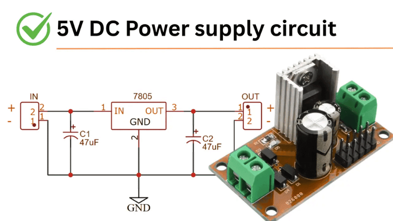
- Linear supplies use a regulator, such as the classic 7805, that drops the excess voltage and burns it off as heat. The output is very clean, but efficiency is often only 40–60%.
- Switching supplies (SMPS) use a MOSFET to chop the high-voltage DC at tens to hundreds of kilohertz. The resulting pulses drive a small high-frequency transformer, which steps the voltage down and provides isolation. On the secondary side, a fast rectifier (often a synchronous MOSFET) and output capacitors turn those pulses back into smooth 5V DC. The controller sets the output by adjusting pulse width (PWM).
Step 6: Monitor the Output
A feedback circuit constantly compares the output voltage with a precise reference. In isolated designs, an optocoupler carries this signal back across the isolation barrier to the controller. If the load suddenly jumps, for example when a Raspberry Pi starts a heavy task, the output dips slightly. The controller responds within microseconds by widening the pulses and pulling the voltage back to 5V.
Step 7: Deliver Power to the Device
The regulated 5V leaves through the output connector. The device draws only the current it needs, up to the supply’s rated maximum.
Built-In Protection During Operation
Protection circuits run in the background the whole time the supply is on. Each protection responds to a specific fault:
- Overcurrent / overload (OCP/OLP): The supply limits output current, folds back the voltage, or enters hiccup mode. In hiccup mode, it shuts down and retries every few hundred milliseconds until the overload clears.
- Short circuit (SCP): Output is cut almost instantly to protect the wiring and the supply itself.
- Overvoltage (OVP): If regulation fails and the output rises, typically to around 5.75–6.75V, the supply clamps or shuts down before connected 5V electronics are damaged.
- Overtemperature (OTP): A thermal sensor shuts the unit down when internal temperature exceeds a safe limit.
Most supplies recover automatically once the fault is removed. Some industrial models latch off and need a power cycle, which prevents repeated restarts into a persistent fault.
Summary Flow
AC Input → Fuse & EMI Filter → Bridge Rectifier → Bulk Capacitors
→ Switching Stage & Transformer (SMPS) or Linear Regulator
→ Output Rectifier & Filter → Feedback Control → Stable 5V DC Output
5V DC Power Supply vs USB Charger
Most USB chargers do output 5V DC. That does not make every USB charger a suitable 5V power supply. The two products are built for different jobs, and the difference matters most when a device runs continuously or depends on stable voltage.
Designed for Different Loads
A USB charger is optimized to refill a battery. The phone or tablet contains its own charging circuit and battery, which buffers any voltage dips. The charger only needs to deliver energy for an hour or two and then idle.
A dedicated 5V power supply is designed to feed a load directly, with no battery in between. Every sag, spike, or ripple on the output reaches the electronics immediately. For that reason, dedicated supplies are specified for:
- tight voltage regulation under changing loads
- low ripple and noise
- continuous full-load operation
- predictable behavior at high ambient temperatures
Connector Compatibility Is Not Electrical Suitability
If a plug fits, it does not mean the power source is right. A USB-C cable will connect a Raspberry Pi to a laptop port, a phone charger, or a power bank. However, a standard USB 2.0 port supplies only 500 mA, and a USB 3.0 port supplies 900 mA. A Raspberry Pi 4 needs up to 3A.
Cables add another variable. Thin charging cables have high resistance, so they lose voltage under load. A charger that measures 5.0V with no load might deliver only 4.6V at the board end of a long, thin cable at 2.5A. The Pi will then show a low-voltage warning and throttle performance.
Fast Charging Protocols vs Basic Regulated 5V
Modern chargers support protocols such as USB Power Delivery (PD) and Qualcomm Quick Charge. These protocols start at 5V and then negotiate higher voltages, such as 9V, 12V, 15V, or 20V, once the device requests them. A device without that negotiation stays at 5V, which is safe.
The catch is current. A charger advertised as “65W” may deliver its full rating only at 20V. At plain 5V, it may be limited to 2A or 3A. The Raspberry Pi 5 is a clear example. It needs a supply that can provide 5V at 5A. On a standard supply, it limits the current available to its USB peripherals.
Why Stable Current Matters for Embedded and Always-On Devices
Microcontrollers and single-board computers are sensitive to brief voltage dips. A Wi-Fi module can pull short current spikes of several hundred milliamps during transmission. If the supply responds slowly, the voltage drops for a moment and the processor can trigger a brownout reset. Over time, repeated brownouts can also corrupt SD cards or flash storage.
Always-on equipment raises separate concerns:
- Thermal stress: Consumer chargers are often not rated for 24/7 operation at full load inside a warm enclosure.
- Auto-shutoff: Many power banks turn off when current drops below about 50–100 mA. A low-power sensor node may draw too little to keep them on.
- Certification: Commercial products must meet safety standards such as IEC 62368-1 for IT equipment or IEC 60601-1 for medical devices. An unmarked consumer charger cannot support that approval.
For kiosks, POS terminals, IoT gateways, control boards, and medical electronics, a purpose-built 5V adapter is the more reliable choice. Quankang’s 5V ITE adapters are certified to IEC 62368-1, and its medical-grade options meet IEC 60601-1 with 2×MOPP isolation.
Factor | Typical USB Charger | Dedicated 5V Power Supply |
|---|---|---|
Primary purpose | Charge batteries | Power devices directly |
Load profile | Short, variable sessions | Continuous, often 24/7 |
Voltage regulation | Adequate for charging circuits | Tight, specified on datasheet |
Ripple and noise | Often not specified | Specified and controlled |
Output voltage | Negotiable (5–20V with PD/QC) | Fixed 5V (or 5.1V/5.2V) |
Certifications | Consumer-level | IEC 62368-1, IEC 60601-1, UL, CE |
Best for | Phones, tablets, accessories | Embedded boards, industrial, medical, kiosks |
Understanding 5V Current Ratings: 1A, 2A, 3A, and More
Voltage must match exactly. Current is more flexible, but it is also where many 5V problems begin.
The Device Draws Only What It Needs
A power supply’s current rating is a maximum, not a fixed amount it forces into the device. A 5V 3A supply connected to a board that needs 0.8A will deliver 0.8A. The unused capacity simply means the supply runs cooler and with less stress. Choosing a higher-rated supply is therefore safe, as long as the voltage is correct.
What Happens When Current Is Too Low
An undersized supply cannot keep up with demand. The results usually follow a predictable pattern:
- Voltage sag: The output drops below 5V under load.
- Resets and dropouts: Microcontrollers reboot, USB devices disconnect, and displays flicker.
- Performance throttling: Single-board computers lower their clock speed to reduce power draw.
- Overheating: The supply runs at or above its limit and may trip its protection circuits repeatedly.
- Shorter service life: Continuous overload ages capacitors and semiconductors faster.
How to Calculate the Required Power
Use the basic power formula:
P = V × I (Power in watts = Voltage × Current in amperes)
For example, a device that needs 5V at 2A requires 5 × 2 = 10W.
Then add 20–30% headroom. This margin covers startup surges, current spikes from wireless modules or motors, gradual component aging, and derating at higher temperatures. For the 10W example, a 25% margin gives 12.5W. A 5V 2.5A or 5V 3A supply would be a sound choice.
Practical Examples
Device / Load | Typical Current at 5V | Recommended Supply |
|---|---|---|
Arduino Uno with a few sensors | 50–500 mA | 5V 1A |
ESP32 or ESP8266 Wi-Fi module | Under 500 mA, with brief spikes | 5V 1A |
Raspberry Pi 4 | Up to 3A with USB peripherals | 5.1V 3A |
Raspberry Pi 5 | Up to 5A with USB peripherals | 5.1V 5A |
1m WS2812B LED strip (60 LEDs) | Up to 3.6A at full white | 5V 5A |
5m WS2812B LED strip (300 LEDs) | Up to 18A at full white | 5V 20A–25A enclosed supply |
Many boards and small projects run comfortably on 1A. Addressable LED installations, by contrast, often need tens of amperes. At those levels, wire gauge becomes as important as the supply itself. Thick cables and power injection points along long strips keep voltage drop under control.
Types of 5V Power Supplies
5V supplies range from pocket-sized USB adapters to rail-mounted industrial units. The right type depends on power level, installation method, and the environment.
Switching Power Supply (SMPS)
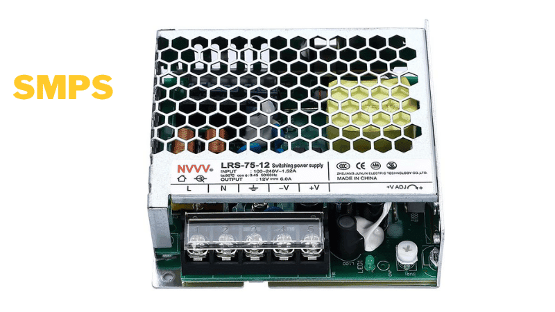
The dominant design for 5V power. It uses high-frequency switching to convert energy efficiently, typically at 75–92% efficiency, in a compact and lightweight package. Most of the other types below are SMPS designs in different form factors. Typical uses include USB adapters, single-board computers, IoT gateways, and networking modules.
Linear Power Supply
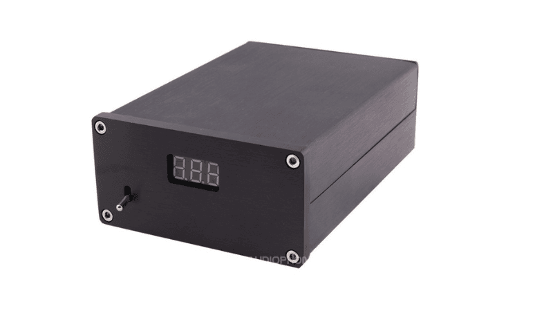
Uses a mains transformer and a linear regulator. It produces very low noise but runs hot, weighs more, and wastes a large share of its input power as heat. It suits noise-sensitive 5V loads such as precision sensors, audio DACs, analog measurement front-ends, and lab reference circuits.
Wall Adapter
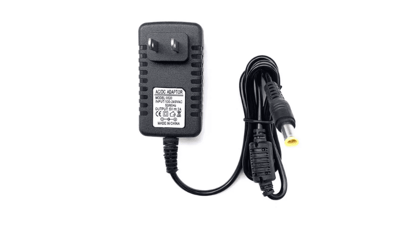
A plug-in unit with an integrated AC plug, available with USB ports, a fixed cable, or a barrel connector. It usually covers 5W to 25W. Common uses include development boards, smart home hubs, set-top boxes, handheld scanners, and small displays.
Enclosed Power Supply
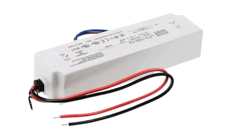
A switching supply in a perforated metal case with screw terminals, designed for fixed mounting. It typically delivers 10A to 60A at 5V. It fits addressable LED installations, LED display panels, digital signage, and cabinets with multiple control boards.
Open-Frame Power Supply
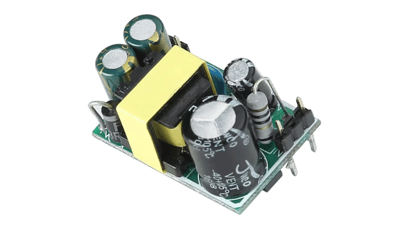
A bare circuit board, sometimes with a mounting bracket, that installs inside a host product’s enclosure. It saves space and cost for OEMs building finished equipment. Examples include POS terminals, kiosks, medical monitors, test instruments, and embedded controllers.
DIN Rail Power Supply
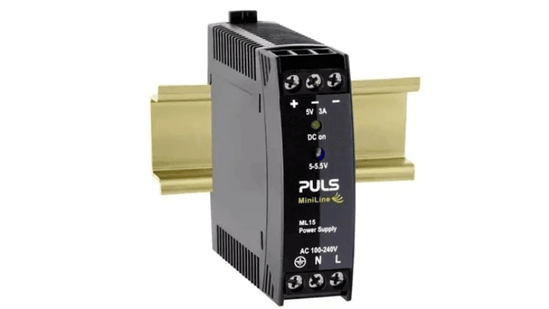
Clips onto a standard 35mm DIN rail inside a control cabinet. These units are rated for industrial temperatures and often include a DC-OK signal output that reports supply status. They are used for PLC logic circuits, industrial sensors, communication modules, and building automation controllers.
Battery-Based Supply
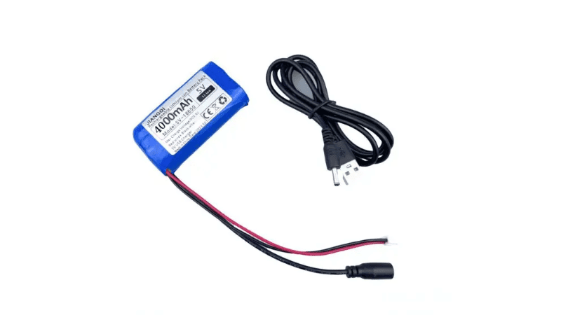
Combines a lithium battery with a boost converter that raises the cell’s 3.7V to a regulated 5V output, usually through USB. Examples include power banks, portable Raspberry Pi projects, remote field sensors, and emergency backup for small devices.
Bench Power Supply
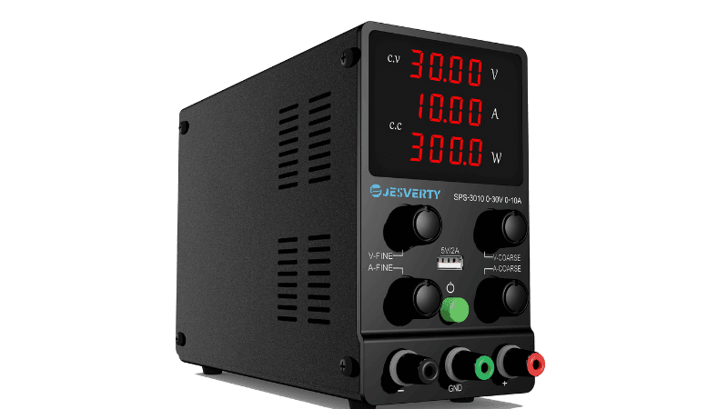
An adjustable lab instrument with voltage and current controls. Setting a current limit protects prototypes from damage during first power-up or when a wiring error occurs. It is standard equipment for firmware development, circuit prototyping, and troubleshooting 5V boards.
Type | Key Features | Main Advantage | Typical 5V Applications |
|---|---|---|---|
SMPS | High-frequency switching | High efficiency, compact size | USB adapters, SBCs, IoT gateways |
Linear | Transformer + linear regulator | Very low noise | Precision sensors, audio, lab circuits |
Wall adapter | Plug-in, 5–25W | Simple and portable | Dev boards, smart hubs, small displays |
Enclosed | Metal case, screw terminals | High current, fixed mounting | LED strips, signage, control cabinets |
Open-frame | Bare PCB module | Easy OEM integration | POS, kiosks, medical monitors |
DIN rail | Rail mount, industrial rating | Cabinet-ready installation | PLCs, sensors, automation |
Battery-based | Lithium cell + boost converter | Works without AC power | Power banks, portable and remote devices |
Bench | Adjustable V and current limit | Safe testing | Prototyping, firmware development |
Common Connector Types
The connector must physically match the device. It must also carry the required current and deliver the correct polarity. Below are the connectors you will meet most often on 5V equipment.
USB-A
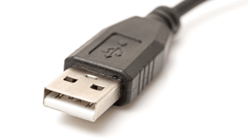
The rectangular port found on chargers, computers, and hubs. Standard ports supply 500–900 mA, while Battery Charging (BC 1.2) ports provide up to 1.5A. USB-A is common for accessories, USB-powered fans and lights, and older development boards.
USB-C
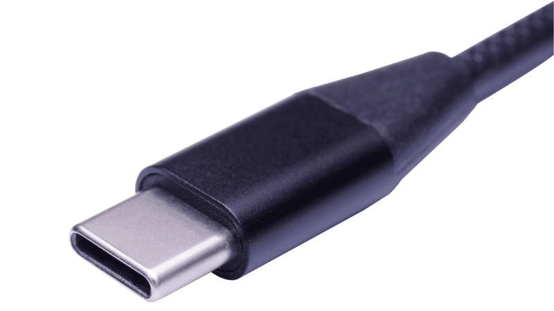
A reversible connector that supports 5V at up to 3A through simple resistor signaling on the CC pins. With Power Delivery, it can negotiate higher voltages. USB-C is now standard on the Raspberry Pi 4 and 5, newer microcontroller boards, and most portable electronics. Some very cheap boards omit the required CC resistors and will not receive power from compliant USB-C chargers.
Micro-USB
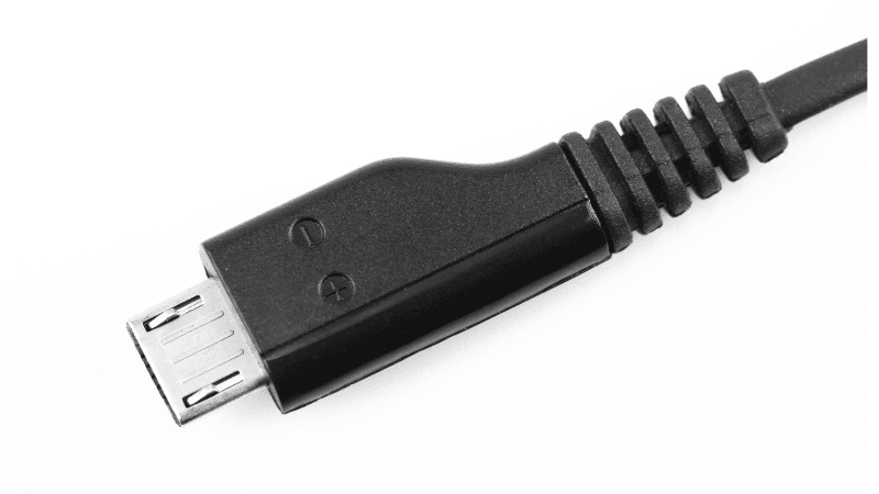
A compact legacy connector typically rated up to about 1.8A. It still appears on the Raspberry Pi 3, ESP8266 modules, older Arduino-compatible boards, and many low-cost sensors. Its small contacts limit current and wear with repeated plugging.
DC Barrel Connector
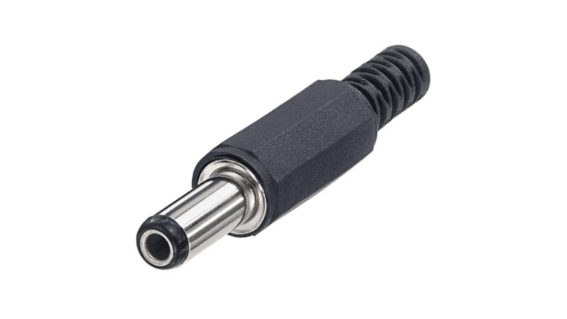
A round plug with a center pin. Common 5V sizes include 5.5×2.1mm, 5.5×2.5mm, and 3.5×1.35mm. Most devices use a center-positive layout, but you should confirm the polarity symbol before connecting. Barrel connectors are widely used on routers, small monitors, set-top boxes, and embedded boards.
Screw Terminals
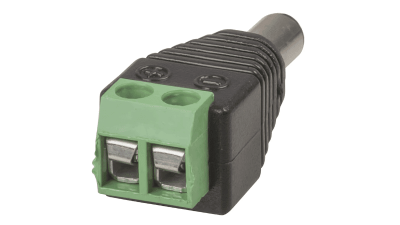
Wires clamp directly under screws, which supports heavy-gauge cable and high current, often 10A or more per terminal. Screw terminals are standard on enclosed and DIN rail supplies for LED installations and control panels.
JST Connectors
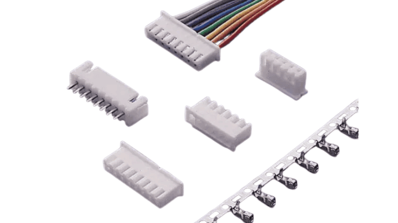
Small, latching board-level connectors. The PH series (2.0mm pitch) is rated around 2A, and the XH series (2.5mm pitch) around 3A. You will find JST connectors on sensor modules, battery packs, small displays, and compact embedded products.
Molex Connectors
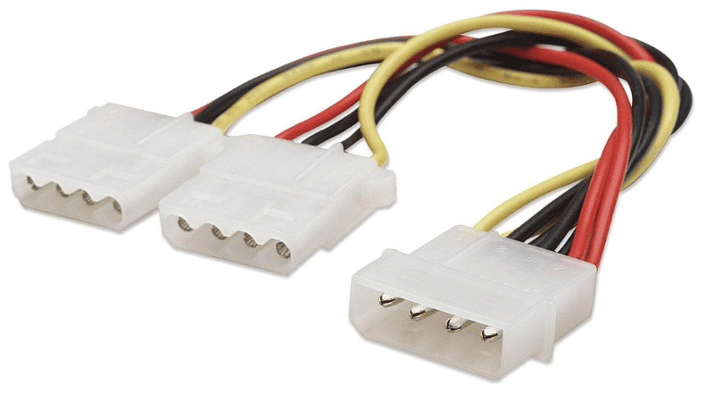
Multi-pin internal connectors with a positive latch. The classic 4-pin peripheral connector carries both 5V and 12V in computers. Molex Micro-Fit connectors are also common in industrial and OEM wiring harnesses. They are used for internal power distribution in computers, storage drives, and embedded systems.
Two-Pin DC Connector
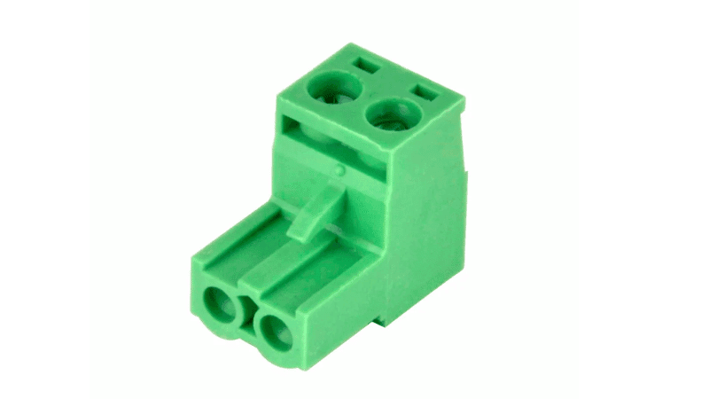
A two-pin DC connector is a simple and practical option for low-voltage power connections. It usually has one pin for positive and one for negative, and many versions are polarized to help prevent incorrect wiring. Because of its straightforward design, it is easy to install and widely used in low-power 5V DC applications. Common uses include LED modules, small motors, sensors, compact electronic devices, and DIY electronics projects. It is especially useful when you need a quick, reliable, low-cost power connection.
Connector | Typical 5V Current | Key Features | Common Applications |
|---|---|---|---|
USB-A | 0.5–1.5A (up to 2.4A on some chargers) | Universal, keyed | Accessories, older boards |
USB-C | Up to 3A at 5V | Reversible, PD-capable | Raspberry Pi 4/5, modern devices |
Micro-USB | Up to ~1.8A | Compact legacy port | Raspberry Pi 3, ESP8266, sensors |
DC barrel | 1–5A depending on size | Plug-and-play, check polarity | Routers, displays, embedded boards |
Screw terminal | 10A+ | Heavy-gauge wiring | LED strips, control panels |
JST (PH/XH) | 2–3A | Small, latching | Sensors, modules, battery packs |
Molex | High, depends on series | Multi-pin, secure latch | PCs, internal harnesses |
Two-pin DC | Low to moderate | Simple +/− connection | LED modules, DIY projects |
Common 5V Power Problems and Voltage Drop
Many 5V failures start between the power supply and the device, not inside the supply itself. The supply may output a clean 5.0V, yet the board receives much less. Cable resistance, connector contacts, and current load cause this loss, and 5V systems feel it more than higher-voltage systems do.
Why 5V Is Especially Vulnerable
Two factors work against 5V at the same time.
- A small margin for error. USB devices expect roughly 4.75V to 5.25V. Many microcontrollers and single-board computers start misbehaving below about 4.6–4.7V. That leaves only a few hundred millivolts of room for loss.
- Higher current for the same power. A 10W load draws 2A at 5V but only 0.83A at 12V. Voltage drop follows Ohm’s law (V = I × R), so more current through the same wire means more lost voltage.
A 0.5V drop is about 4% of a 12V supply. On a 5V supply, the same drop is 10%, which is enough to push most digital electronics out of their safe operating range.
Practical Causes of Voltage Drop
Cable gauge. Thin wire has higher resistance. Many low-cost USB cables use 28 AWG power conductors, which work for charging but struggle at 2A or more. Current also travels out and back, so the effective wire length is twice the cable length.
Wire Gauge | Resistance per Meter | Drop at 2A, 1m Cable (Round Trip) | Voltage at Device (from 5.0V) |
|---|---|---|---|
28 AWG | ~0.213 Ω | ~0.85V | ~4.15V |
24 AWG | ~0.084 Ω | ~0.34V | ~4.66V |
22 AWG | ~0.053 Ω | ~0.21V | ~4.79V |
20 AWG | ~0.033 Ω | ~0.13V | ~4.87V |
Cable length. Voltage drop grows in direct proportion to length. A 2m cable loses twice as much as a 1m cable of the same gauge. Cheap USB extension cables make this worse.
Connector quality. Every contact point adds resistance. Worn Micro-USB ports, loose barrel plugs, oxidized screw terminals, and poorly crimped JST pins can each add tens of milliohms. At high current, the connector also heats up, which raises its resistance further.
Current load. Voltage drop that looks harmless at idle can become a problem under full load. A Raspberry Pi may boot fine, then fail when the CPU runs a heavy task or a USB drive spins up.
Real-World Symptoms
- Random resets: Microcontrollers trigger brownout protection and reboot, often during Wi-Fi transmission or motor startup.
- Throttling and warnings: Raspberry Pi boards display a lightning-bolt icon or log “under-voltage detected,” then lower their clock speed.
- SD card and flash corruption: A voltage dip during a write operation can damage the file system, leaving the device unable to boot.
- USB disconnects: Keyboards, cameras, and storage drives drop off and reconnect.
- Color shifts in LED strips: On long addressable LED runs, the far end turns yellow or red because blue and green LEDs need more voltage.
How to Prevent It
- Use short, thick cables rated for the current you need (22 AWG or heavier for 2A+ loads).
- Choose a supply with a 5.1V or 5.2V output for single-board computers.
- Inject power at several points along long LED strips instead of feeding only one end.
- Replace worn connectors and tighten screw terminals.
- For long cable runs, distribute 12V or 24V and convert to 5V near the load with a DC-DC converter.
Pros and Cons of a 5V Power Supply
5V is an excellent choice for low-power electronics, but its strengths and limits come from the same fact: it is a very low voltage.
Advantages
- SELV safety: 5V sits well within the safety extra-low voltage range. It poses almost no shock risk, which suits handheld products, classrooms, and user-accessible equipment.
- A universal USB ecosystem: Every USB port, charger, and power bank can supply 5V. Replacement adapters and cables are easy to find worldwide.
- Wide component compatibility: Many microcontroller boards, sensor modules, relay boards, displays, and communication modules accept 5V directly.
- Compact, efficient SMPS designs: Modern switching supplies reach 75–92% efficiency in small, light packages, from pocket USB adapters to slim open-frame modules.
- Simple integration: A single lithium cell with a boost converter can produce 5V, so the same device can run from mains power or a battery.
Disadvantages
- High current at the same wattage: A 50W load needs 10A at 5V, compared with about 4.2A at 12V or 2.1A at 24V. Higher current means thicker wires, larger connectors, and more heat.
- Sensitivity to voltage drop: Even a small loss in cables or contacts is a large share of the total voltage, which limits cable length and demands good connectors.
- Poor fit for high-power loads: Motors, heaters, large displays, and heavy industrial equipment are impractical at 5V. They use 12V, 24V, 48V, or mains power instead.
- Limited distribution distance: 5V is best delivered close to the load. Large systems usually distribute a higher voltage and step down locally.
Advantages | Disadvantages |
|---|---|
SELV-level safety | High current required for higher wattage |
Universal USB compatibility | Very sensitive to cable and connector losses |
Broad support in digital electronics | Not suited to motors or high-power loads |
Compact, efficient switching designs | Short practical distribution distance |
Easy battery integration | Needs thicker wiring at higher currents |
Applications of 5V DC Power Supplies
5V powers a wide range of equipment, from hobby boards to certified commercial products. Requirements differ by application, so the right supply does too.
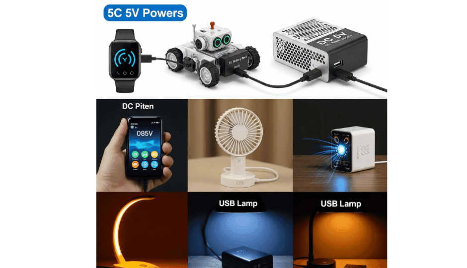
- USB-powered devices. Webcams, USB hubs, card readers, portable fans, desk lamps, and small speakers all run on 5V USB power. Most draw under 1A, although bus-powered hubs with several devices can need 2–3A.
- Raspberry Pi and single-board computers. The Raspberry Pi 4 needs 5.1V at 3A, and the Pi 5 needs 5.1V at 5A for full USB peripheral current. These boards are sensitive to low voltage, so a dedicated supply with a short, heavy cable works best.
- Arduino and microcontroller boards. Arduino Uno, Nano, and many ESP32 development boards accept 5V through USB or a 5V pin. A 5V 1A supply covers most setups with a few sensors and a small display.
- IoT sensors and gateways. Environmental monitors, smart meters, and wireless gateways often run 24/7. They need stable output, low standby power, and long service life rather than high current.
- Addressable LED strips. WS2812B and similar LEDs run on 5V and can draw up to about 60 mA per LED at full white. Large installations use enclosed 5V supplies rated at 20A to 60A, with power injection along the strip.
- Networking and communication gear. Compact routers, USB modems, media converters, and wireless access modules often use 5V barrel or USB inputs. Continuous operation makes thermal performance and regulation important.
- POS terminals and kiosks. Card readers, receipt printers, barcode scanners, and touchscreen controllers in retail systems often use internal or external 5V supplies. These products must meet IEC 62368-1 and run reliably through long business hours.
- Medical and portable instruments. Patient monitors, pulse oximeters, portable diagnostic tools, and lab instruments may run on 5V. Medical equipment must use supplies certified to IEC 60601-1, with low leakage current and 2×MOPP isolation where patients are involved.
- Industrial embedded systems. PLC logic boards, HMI panels, data loggers, and sensor interfaces use 5V for digital circuits. DIN rail and open-frame 5V supplies handle the wider temperature ranges and electrical noise found in factories.
- Portable and battery-powered electronics. Power banks, handheld scanners, field test tools, and solar-charged devices boost a lithium cell to 5V. Low quiescent current and stable output under changing loads matter most here.
How to Test a 5V Power Supply
A digital multimeter is the quickest way to confirm whether a 5V supply works correctly. Testing without a load shows only part of the picture, so always check the output under a realistic load, too.
Tools Needed
- Digital multimeter (DMM) with a DC voltage range
- Insulated test leads
- The 5V power supply under test
- A known load, such as a 5Ω 10W power resistor (draws 1A at 5V), an electronic load, or the target device
- A USB breakout board or inline USB power meter for USB-output supplies
- Safety glasses for open-frame or high-current units
For USB-C supplies, a standard cable-to-probe test may show 0V even when the supply is healthy. Compliant USB-C chargers only turn on VBUS after they detect a device through the CC pins. Use a USB-C breakout with the correct resistors or a USB-C power meter instead.
7 Testing Steps
1. Inspect the supply.
Check the housing, cable, and connector for cracks, scorch marks, bulging, bent pins, or melted plastic. Do not power a unit with visible damage.
2. Set the multimeter.
Select DC voltage mode (V⎓). On a manual-ranging meter, choose the 20V DC range for good resolution at 5V.
3. Identify polarity and connect the probes.
Place the red probe on the positive output and the black probe on ground. On USB-A, VBUS (+5V) is pin 1 and ground is pin 4. On a barrel plug, the center is usually positive, but confirm the polarity marking. On screw terminals, use the V+ and V− labels.
4. Measure the no-load voltage.
Power on the supply and read the display. A healthy unit should read between about 4.95V and 5.25V. Supplies designed for single-board computers may read 5.1–5.2V by design.
5. Test under load.
Connect the load and measure again at the load terminals. A 5Ω resistor draws 1A. For a 3A supply, use a 1.67Ω resistor or an electronic load set to 3A. The voltage should stay close to the no-load reading, ideally within 0.1–0.2V.
6. Check stability over time.
Leave the load connected for 10–15 minutes and watch for drift, flicker, or sudden drops. A reading that slowly falls as the unit warms up can point to aging capacitors or thermal stress.
7. Check heat and noise.
Carefully touch the housing after the load test. Warm is normal, but too hot to hold is not. High-pitched whining, buzzing, or a burning smell signals internal trouble. Note that a multimeter cannot measure ripple. Use an oscilloscope if you suspect noise problems in sensitive circuits.
Common Test Results
Multimeter Reading | Likely Condition | What to Do |
|---|---|---|
About 5V (4.95–5.25V) | Operating normally | Confirm the reading holds under load |
0V | No output, protection triggered, or internal failure | Check the input, fuse, and connector; for USB-C, use a proper tester |
Below 4.8V | Overload, voltage drop, or weak supply | Reduce the load, shorten the cable, or replace the supply |
Above 5.2V (on a standard 5V unit) | Regulation fault or 5.1–5.2V design | Check the datasheet; replace the unit if it exceeds the spec |
Unstable or fluctuating | Failing regulator, loose connection, or aging capacitors | Reseat connections and retest; replace the unit if it persists |
Safety Tips
- Never open a mains-powered supply while it is plugged in. Bulk capacitors can hold a dangerous charge even after unplugging.
- Keep fingers away from the AC input side of open-frame modules.
- Do not short the output terminals with probes.
- Make sure your power resistor has an adequate wattage rating, since it will get hot.
- Disconnect power before changing any wiring.
How to Choose the Right 5V Power Supply
The right 5V supply matches your device electrically, fits the installation, and holds up for the life of the product. Work through these criteria in order.
Match the voltage. Confirm that the device needs 5V DC. For single-board computers and long cable runs, a 5.1V or 5.2V output helps offset cable loss.
Build in current headroom. Add up the maximum current of the device and anything it powers, then add 20–30%. A board that peaks at 2.4A should use a 5V 3A supply.
Pick the correct connector. Match the type (USB-A, USB-C, Micro-USB, barrel, JST, or screw terminal), the size (such as 5.5×2.1mm vs 5.5×2.5mm), and the polarity. Also check that the connector and cable are rated for the current.
Consider the environment. Note the ambient temperature, humidity, dust, vibration, and ventilation. Supplies inside sealed enclosures often need derating, so check the derating curve on the datasheet.
Choose the right supply type. A wall adapter suits a single device. An open-frame module fits OEM equipment. A DIN rail unit belongs in a control cabinet. An enclosed supply handles high-current LED systems.
Check the protection features. Look for OVP, OCP, SCP, and OTP at a minimum. For unattended equipment, auto-recovery after a fault prevents unnecessary service calls.
Compare efficiency and standby power. Higher efficiency means less heat and a longer component life. For devices that are always plugged in, low no-load power consumption also reduces energy costs and helps meet efficiency standards such as DOE Level VI.
Verify the certifications. IT and communication equipment should use supplies certified to IEC 62368-1. Medical devices need IEC 60601-1. Depending on the target market, also look for UL, CE, FCC, UKCA, and RoHS marks.
Work with a trusted manufacturer. Datasheet accuracy, consistent production quality, and long-term availability matter as much as the specs. Quankang brings more than 30 years of power supply manufacturing experience. Its 5V ITE adapters are certified to IEC 62368-1, and its medical power supplies meet IEC 60601-1 with 2×MOPP isolation. OEM and ODM customization is available for projects that need specific connectors, cable lengths, or output settings.
Quick Selection Checklist
Factor | What to Check |
|---|---|
Output voltage | 5V DC (5.1–5.2V for SBCs or long cables) |
Output current | Device maximum plus 20–30% headroom |
Connector | Correct type, size, polarity, and current rating |
Cable | Short length and adequate gauge for the load |
Supply type | Wall adapter, open-frame, enclosed, DIN rail, or bench |
Environment | Temperature range, derating, ventilation, and moisture |
Protection | OVP, OCP, SCP, OTP, and recovery behavior |
Efficiency | High active efficiency and low standby power |
Certifications | IEC 62368-1, IEC 60601-1 (medical), UL, CE, FCC, RoHS |
Manufacturer | Proven track record, accurate datasheets, and support |
Common Problems and Troubleshooting
Most 5V power issues trace to a few common causes. Use this table to narrow down the problem before replacing parts.
Problem | Possible Cause | Recommended Solution |
|---|---|---|
No output | No AC input, blown fuse, protection latched, failed internal component, or USB-C supply waiting for device detection | Check the outlet and input cable, then power-cycle the unit. Test USB-C with a proper tester. Replace the supply if it stays dead. |
Low voltage | Overload, undersized or long cable, worn connector, or aging capacitors | Measure at the supply and at the device to locate the drop. Use a shorter, heavier cable or a higher-current supply. |
Unstable output | Loose connection, failing regulator, or heavy load spikes | Reseat all connectors and tighten terminals. Retest under steady load, and replace the unit if the reading still fluctuates. |
Overheating | Running near full load, poor ventilation, or high ambient temperature | Reduce the load, improve airflow, or choose a supply with more headroom or a higher temperature rating. |
Automatic shutdown | Short circuit, overcurrent, or overtemperature protection triggered | Disconnect the load and check for shorts. Let the unit cool, then restart with a reduced or verified load. |
Buzzing or whining noise | Coil or transformer vibration under certain loads, or a failing component | Faint noise at light load can be normal. Loud or new noise, especially with heat or a smell, means you should replace the unit. |
Incorrect polarity | Reversed barrel plug, swapped screw terminal wires, or wrong adapter | Power off immediately. Verify polarity with a multimeter before reconnecting, and check the device for damage. |
Loose connectors | Worn USB or barrel ports, loose terminals, or poor crimps | Replace worn cables or plugs, re-crimp JST pins, and use connectors with a secure latch in high-vibration settings. |
Frequently Asked Questions
What does 5V supply mean?
A 5V supply is a power source that delivers a steady 5 volts of direct current to electronic devices. The “5V” is the output voltage, and the supply’s current rating tells you the maximum load it can handle. It is the base voltage of USB power and one of the most common voltages in digital electronics.
What is a DC power supply?
A DC power supply is a device that provides direct current, meaning electricity that flows in one direction only. Most DC power supplies convert AC from a wall outlet into regulated DC at a fixed voltage, such as 5V, 12V, or 24V. Electronic circuits need DC to operate correctly.
What can I power with 5V DC?
You can power USB accessories, Arduino and ESP32 boards, Raspberry Pi computers, IoT sensors, addressable LED strips, small displays, card readers, and many handheld instruments. Always check that your supply’s current rating meets or exceeds the device’s needs.
Is 5V DC the same as 120V?
No. 120V is the alternating current supplied by household outlets in North America, and it is dangerous to touch. 5V DC is a very low-voltage direct current used by small electronics. A power adapter is always required between the two, and you must never connect a 5V device directly to mains power.
What does a 5V plug look like?
Most 5V devices use USB connectors, including USB-A, USB-C, and Micro-USB. Others use a round barrel plug, often 5.5×2.1mm or 3.5×1.35mm. Industrial supplies typically use screw terminals, and compact modules may use small JST connectors. Check your device’s input port and polarity marking before buying a supply.
How do I get 5V DC at home?
The simplest option is a certified USB wall adapter or a 5V plug-in adapter. Computer USB ports and power banks also provide 5V, although USB ports usually supply only 500–900 mA. For projects that need more current, use a dedicated 5V supply with the right rating.
Can I use a battery charger as a 5V power supply?
It depends on the charger type. A USB phone charger outputs regulated 5V and can power many small devices, although it may not be stable enough for always-on embedded systems. A lithium-ion cell charger is not suitable. It outputs about 4.2V per cell and changes its voltage and current during the charge cycle, so it cannot provide a steady 5V.
Is 5V DC equal to 5V AC?
No. DC flows in one direction at a constant level, while AC reverses direction 50 or 60 times per second. Electronic circuits that need 5V DC can be damaged or fail to run on 5V AC, so you can’t swap them.
Is 5V a lot of electricity?
No. 5V falls within the safety extra-low voltage (SELV) range, and you generally cannot feel it through dry skin. However, a 5V supply can still deliver high current. A short circuit on a 20A unit can melt wires or cause burns, so correct wiring and protection circuits still matter.
How do I connect a 5V power supply?
For USB or barrel-connector devices, plug in a cable that matches the input port and has the correct polarity. For screw-terminal supplies, switch off the AC power first. Connect the device’s positive wire to V+ and negative to V−, then check polarity with a multimeter before turning on the supply. Use wire rated for the load current and keep the cable as short as practical.
Conclusion
A 5V DC power supply powers a huge range of equipment, from USB accessories and Raspberry Pi boards to IoT gateways, POS terminals, and medical instruments. Correct installation keeps it reliable: use short, heavy cables and secure connectors, allow good ventilation, and test the output under load before you trust it in service. When you select a supply, match the voltage, add 20–30% current headroom, choose the right connector and form factor, and insist on proper certifications from a proven manufacturer such as Quankang.