Open up almost any modern gadget, and you’ll find a switch-mode power supply quietly doing the heavy lifting. Your laptop charger, phone adapter, and desktop PC all rely on one. After decades of designing and troubleshooting these circuits, I can tell you they’re one of the most elegant solutions in power electronics.
This guide is for engineers, technicians, and serious hobbyists who want a solid grasp of the fundamentals. By the end, you’ll understand how an SMPS works, what’s inside one, which topology fits your project, and how to pick the right unit without guesswork.
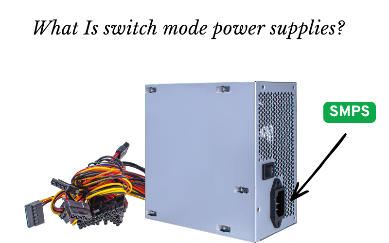
A switch-mode power supply (SMPS) is a circuit that converts power using high-speed switching devices instead of burning off extra energy as heat. That single difference is why it largely replaced older linear designs. Linear supplies waste a lot of power and run hot. SMPS units stay efficient, compact, and cool by comparison.
How an SMPS Works
The core idea is simple once you see it. Instead of slowly trimming voltage like a linear supply, an SMPS chops the power into fast pulses, then smooths it back into clean DC.
Here’s the key insight: a switching transistor wastes very little power when it’s fully on or fully off. It only loses energy during the brief moment it transitions between those two states. Keep those transitions short and fast, and you keep efficiency high.

PWM and Duty Cycle
The control trick behind all of this is Pulse Width Modulation (PWM). The supply rapidly turns the transistor on and off, and the ratio of on-time to total cycle time is called the duty cycle.
Want more power at the output? Widen the on-time. Need less? Shorten it. By adjusting the duty cycle, the supply controls exactly how much energy reaches the load.
The Conversion Steps
The journey from wall outlet to clean DC follows a clear path:
- The incoming AC is rectified into high-voltage DC.
- The transistor switches that DC at high frequency, often 20 kHz to several MHz.
- An inductor or transformer stores and transfers that energy each cycle.
- The output stage filters the result back into steady, usable DC.
The Feedback Loop
This is where the magic of regulation happens. A feedback circuit constantly watches the output voltage and compares it to a fixed reference.
If the output drifts too high, the loop trims the duty cycle. If it sags, the loop widens it. This happens thousands of times per second, so your output stays rock-steady even when the load jumps around.
Good designs also handle input variation well. Wide-range controllers and input filtering let the supply hold a stable output whether your mains sits at 100V or 240V. That’s why your laptop charger works in nearly any country.
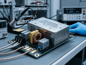
Main Components of a Switching Power Supply
Knowing the parts helps you read a schematic and diagnose problems faster. Most SMPS units share the same building blocks.
- Input rectifier and filter — turns incoming AC into high-voltage DC and smooths the ripple.
- Inverter stage — the switching MOSFETs or transistors that chop the DC at high frequency.
- High-frequency transformer — provides electrical isolation and steps up or down the voltage. Because it runs at high frequency, it can be far smaller than a linear transformer.
- Output rectifier and filter — converts the high-frequency signal back into a steady DC.
- Feedback circuit — monitors output voltage and adjusts switching timing in real time.
- Snubbers and protection circuitry — tame voltage spikes and protect the switching devices, which improves long-term reliability.
A quick tip from the bench: when an SMPS fails, the input capacitors, switching transistor, or output diodes are usually the first suspects.

Popular Topologies and When to Use Each
Topology is just the arrangement of the circuit that performs the conversion. Picking the right one depends mostly on your power level and how your input and output voltages relate.
Lower-Power Designs
For smaller loads, simpler topologies do the job well:
- Buck converter — steps voltage down. Use it when your output needs to be lower than your input. Common inside boards that drop 12V to 3.3V or 5V.
- Boost converter — steps up the voltage. Reach for it when the output must sit higher than the input, like driving LED strings from a battery.
- Flyback converter — a low-cost favorite for chargers and small adapters under roughly 100W. It provides isolation with a minimal part count.
Medium and High-Power Designs
As power climbs, you need topologies built for the heat and current:
- Forward converter — a solid choice for medium-power applications that need better efficiency than a flyback can deliver.
- Push-Pull and Half-Bridge — used in higher-power industrial equipment. They handle large currents more smoothly and use the transformer more efficiently.
Common mistake: trying to stretch a flyback design into a high-power application. Match the topology to the wattage from the start and you’ll save yourself a redesign.
SMPS vs Linear Power Supplies
Both have their place, but they solve the problem in very different ways. Here’s how they stack up at a glance.
Factor | SMPS | Linear |
|---|---|---|
Efficiency | 80–90% | ~40% |
Size & weight | Compact, light | Bulky, heavy |
Heat | Low | High |
Cost | More complex parts | Simpler, but more raw material |
Noise/EMI | Higher needs filtering | Very low, quiet |
The efficiency gap is the headline. An SMPS dissipates little power because its switch is either fully on or fully off. A linear supply dissipates the voltage drop as heat, which is why it needs large heatsinks and wastes energy.
If you need clean, quiet power for sensitive analog work, a linear supply still wins on noise. For nearly everything else, especially anything battery-powered or high-wattage, the SMPS is the practical pick.
Benefits and Drawbacks of Switching Technology
No design is perfect. Knowing the trade-offs helps you avoid surprises later.
The strengths are real:
- Compact and lightweight design.
- High efficiency that cuts heat and energy waste.
- Wide input voltage range, so one unit works across regions.
The drawbacks deserve respect too:
- Design complexity — control circuits need more parts and a careful PCB layout. Sloppy layout causes most early-stage headaches.
- EMI — fast switching edges and high frequencies generate electromagnetic interference. You’ll need filtering and sometimes shielding to meet limits.
- Switching frequency trade-offs — raising the frequency reduces component size but increases switching losses. There’s always a balance point.
- Power factor correction (PFC) — higher-power units often require PFC to keep the input current clean and comply with regulations.
- Thermal management — high heat or cheap capacitors — is the leading cause of early failure. Spend on quality caps; you’ll thank yourself.
Selection Tips for Your Project
Picking the right supply comes down to a handful of practical checks. Run through this list before you buy.
- Calculate your power needs first. Add up the total wattage and the peak current your device draws at startup, not just its steady state. Build in headroom.
- Confirm the certifications. Look for UL, CE, or other marks required by your market. Skipping this stalls products at inspection.
- Plan the cooling. Decide between natural convection and active cooling with a fan based on your wattage and enclosure.
- Check the environment. Operating temperature and humidity matter. A unit rated for a clean office may fail in a hot, dusty plant.
- Match the input range. Make sure the supply accepts your power source and any regional voltage variation.
- Read the data sheet closely. Verify ripple voltage, regulation, and thermal ratings before committing. These numbers show how the unit behaves under real-world load.
If you’re on a tight timeline, prioritize wattage headroom and certifications first. Those two cause the most expensive mistakes.
Frequently Asked Questions
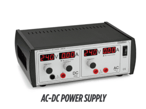
What is the difference between AC-to-DC and DC-to-DC switching supplies?
An AC-to-DC supply takes wall power and converts it to DC, starting with a rectifier stage. A DC-to-DC supply takes an existing DC source, such as a battery, and converts it to a different DC voltage. Both use switching, but DC-to-DC units skip the AC rectification step.
Why do switching power supplies make a high-pitched whining sound?
That whine usually comes from components vibrating at the switching frequency, often a transformer or ceramic capacitor. Light loads can push the frequency into your hearing range. It’s common and usually harmless, though a sudden new noise can hint at a failing part.
Can I use an SMPS for sensitive audio equipment?
You can, but choose carefully. Standard SMPS units inject electrical noise that may appear as a hum or hiss. Look for low-noise designs with strong filtering, or use a linear supply for the most sensitive analog stages.
How do I reduce electromagnetic interference in my SMPS design?
Start with a tight PCB layout and short, direct switching loops. Add input and output filters, use snubbers to tame voltage spikes, and add shielding where needed. Good grounding does more than almost anything else.
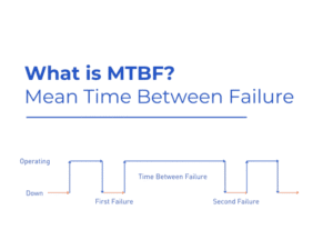
What causes a switching power supply to fail prematurely?
Heat is the usual killer, especially when it dries out electrolytic capacitors. Poor-quality caps, overloading, and inadequate cooling all shorten lifespan. Running a unit near its maximum rating for long stretches will age it fast.
When should I choose an SMPS over a linear supply?
Choose an SMPS when you need efficiency, compact size, light weight, or a wide input range. Reach for a linear supply only when low noise matters more than everything else, and the power level stays small.
Choosing the Right Power Solution
The switch-mode power supply earns its place in modern electronics for good reason. It delivers high efficiency, a small footprint, and flexible input handling that linear designs simply can’t match.
Yes, the design is more complex. But the gains in size, heat, and efficiency are hard to ignore. The key is to match your topology and ratings to your application’s real demands, not just its average ones.
If you’re building a prototype or working on a hobby project, start with a quality pre-built module. It removes most of the layout and EMI headaches so you can focus on your actual design.
Before you finalize any purchase, pull the data sheet and check the ripple voltage and thermal ratings. A few minutes of reading now saves hours of troubleshooting later. What’s the toughest power challenge in your current project?