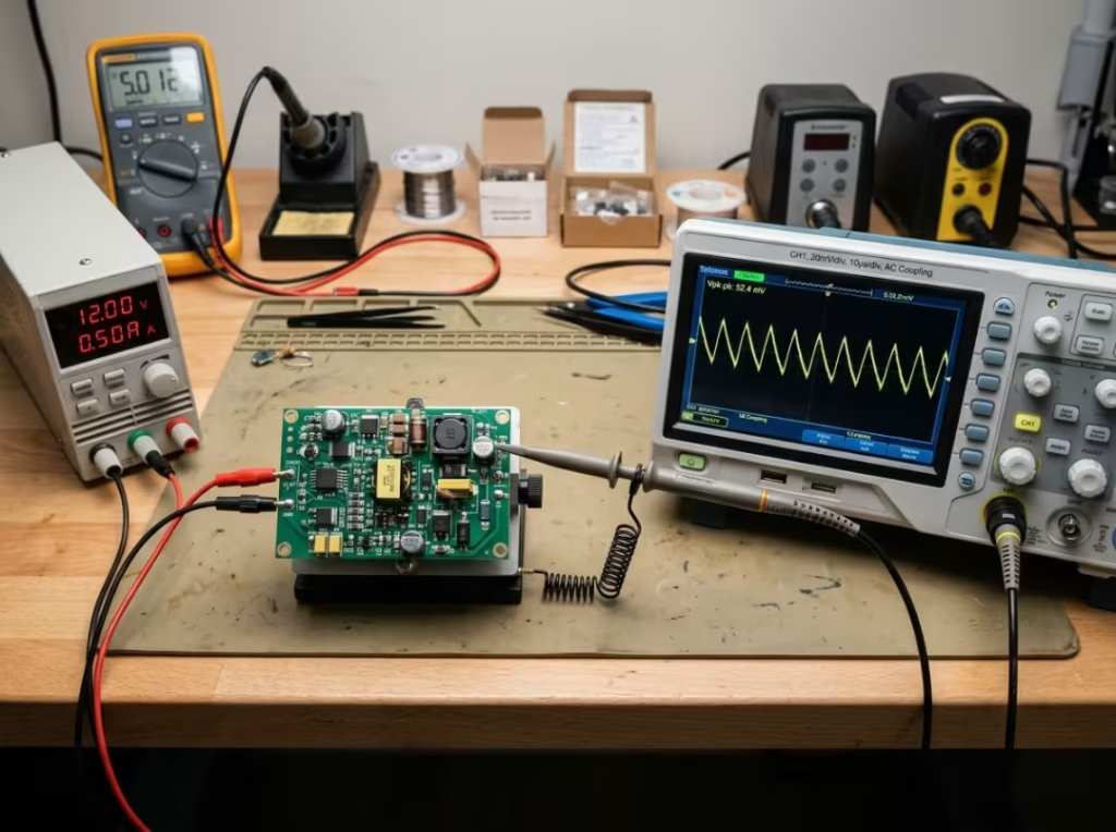
Put two engineers on the same power rail, and you can easily get two very different ripple numbers. The supply didn’t change between measurements. The setup did. Change the probe ground, the bandwidth limit, or where exactly you’re probing, and the figure on screen stops meaning what you think it means.
This guide covers three things: how to measure ripple so the number is accurate, how to spot when a reading is misleading, and how to turn a real result into a useful diagnosis.
What You’re Actually Measuring
The first problem is that “ripple” gets used as a catch-all for everything ugly on a rail. There are really three distinct things in that bundle.
Ripple is the periodic AC component superimposed on the DC output. It locks to a fixed frequency — the line frequency in a linear supply, the switching frequency and its harmonics in a switcher. Rails supplying precision analog, ADC front ends, or patient-adjacent electronics — as found in medical power supplies — are especially sensitive to even small periodic excursions, which is why measurement accuracy matters long before any pass-fail judgment is made.
Noise is broadband and random: spikes, hash, and ringing that don’t track any single frequency. Most of it comes from switching transitions and parasitic resonances.
Transient residue is the dip or overshoot that appears after a load step while the feedback loop catches up. It’s real and worth characterizing, but it’s not steady-state ripple and shouldn’t be folded into that number by accident.
These three aren’t measured or judged the same way, which is exactly why the distinction matters before you touch the scope. Your settings decide which components land in the result. A datasheet specifying “ripple” under a 20 MHz bandwidth limit is a fundamentally different measurement from one specifying “ripple and noise” with the bandwidth wide open. If your setup doesn’t match the conditions behind the number you’re comparing against, the comparison isn’t valid — even if the equipment is identical. The scope doesn’t reveal the truth. It reveals the truth inside the measurement window you built.
Why Ripple Readings Go Wrong So Easily
The same rail can look clean or terrible depending on how you probe it
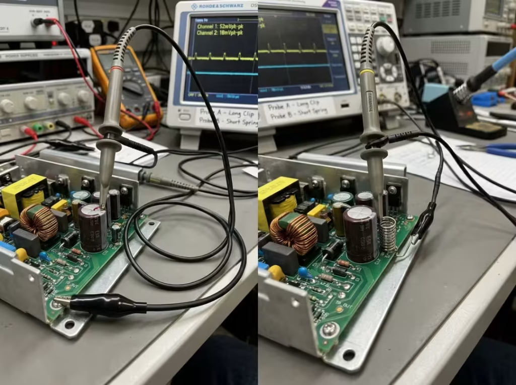
The long alligator ground clip is responsible for more false ripple failures than most genuinely bad power designs. Once that lead forms a large loop, it stops being a neutral return path and starts acting as an antenna, coupling in switching noise from the surrounding environment. What you’re seeing on screen may have nothing to do with what the output capacitor is actually producing.
Here’s the test that makes this concrete. Measure a switching rail with the standard alligator clip and note the peak-to-peak. Then swap to a ground spring and measure the same point. The reading often drops by a large factor — sometimes dramatically. The rail didn’t change. The measurement loop did.
What datasheet ripple numbers usually assume
A datasheet ripple figure rarely stands alone. It comes bundled with unstated assumptions:
- Peak-to-peak, not RMS
- A defined bandwidth, very often 20 MHz
- A specific load condition, typically full rated load
- A defined measurement point, usually across the output capacitor
- A specific probe method or recommended setup
Ignore any of those and the comparison breaks before it starts. Missing the bandwidth assumption alone is enough to make a compliant supply appear to fail.
Rule out your setup before you blame the supply
A noisy reading does not automatically mean a noisy supply. Before you redesign a filter stage or reject a unit, you need confidence that the measurement itself is honest. In ripple work, diagnosing the converter before validating the setup is the fastest way to waste an afternoon. Get the measurement right first. Then the pass-fail conversation means something.
Building a Measurement Setup You Can Trust
This is where most ripple measurements actually go wrong — not at the acquire button.
Setup quality matters more than oscilloscope specs
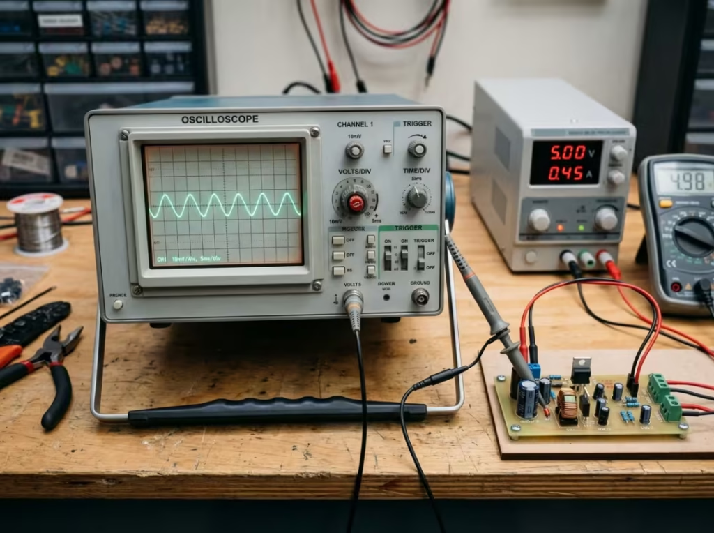
Most ripple measurements fail due to poor connection quality, not because the oscilloscope is underpowered. A 100 MHz scope covers most standard ripple checks, especially with the 20 MHz bandwidth limit in place. If you need to characterize fast switching noise and ringing, a 500 MHz scope gives you a more accurate picture — but that’s a separate task from verifying a ripple spec. A modest scope with a clean probe path tells you more than a high-end scope attached badly. Build the measurement path first, then consider whether you need more bandwidth.
Know when a passive probe is enough — and when it isn’t
A standard 10x passive probe is the right starting point for most low-voltage DC rail measurements. What matters more than probe type is whether it’s properly compensated and connected short. An uncompensated probe distorts fast edges and high-frequency content, shifting the apparent waveform cleanly or sloppily in ways that don’t reflect the rail. Check compensation against the scope’s built-in square wave before every measurement session.
Two situations call for a different approach. A short coaxial connection — a 50-ohm-terminated coax or a piece soldered directly to the test point — removes the probe tip and ground lead entirely, giving you the cleanest possible ripple view. A differential probe is the right tool when the node can’t safely share scope ground: floating supplies, high-side switching nodes, and setups where common-mode pickup or ground loops are part of the problem. Never clip a grounded passive probe onto a non-isolated high-side node. The goal isn’t more hardware; it’s removing avoidable uncertainty from the measurement path.
Probe grounding is where trustworthy measurements begin
If you make one change to your ripple technique, shorten the ground path.
The difference between a long ground clip and a ground spring is not cosmetic. It’s often large enough to flip a pass result into a fail. That long lead forms a loop, and in a switching power environment the loop area couples in noise that has nothing to do with what the output capacitor is putting on the rail. The measurement loop becomes part of the measurement result.
In order of preference:
- Ground spring slipped over the probe tip, replacing the alligator clip. This shortens the return to a few millimeters and eliminates most pickup.
- Tip-and-barrel adapter or a short wire soldered from the probe barrel directly to the nearest ground point.
- Coax soldered directly to the test point, when you want the lowest-noise reference available.
Keep the return path as short as the board layout allows. A forest of spikes on the screen doesn’t necessarily mean the rail is carrying those spikes. It often means the loop is generating them.
Measure at the right physical point
A ripple reading only makes sense when you know exactly which point it represents. Two locations on the same rail answer two different questions.
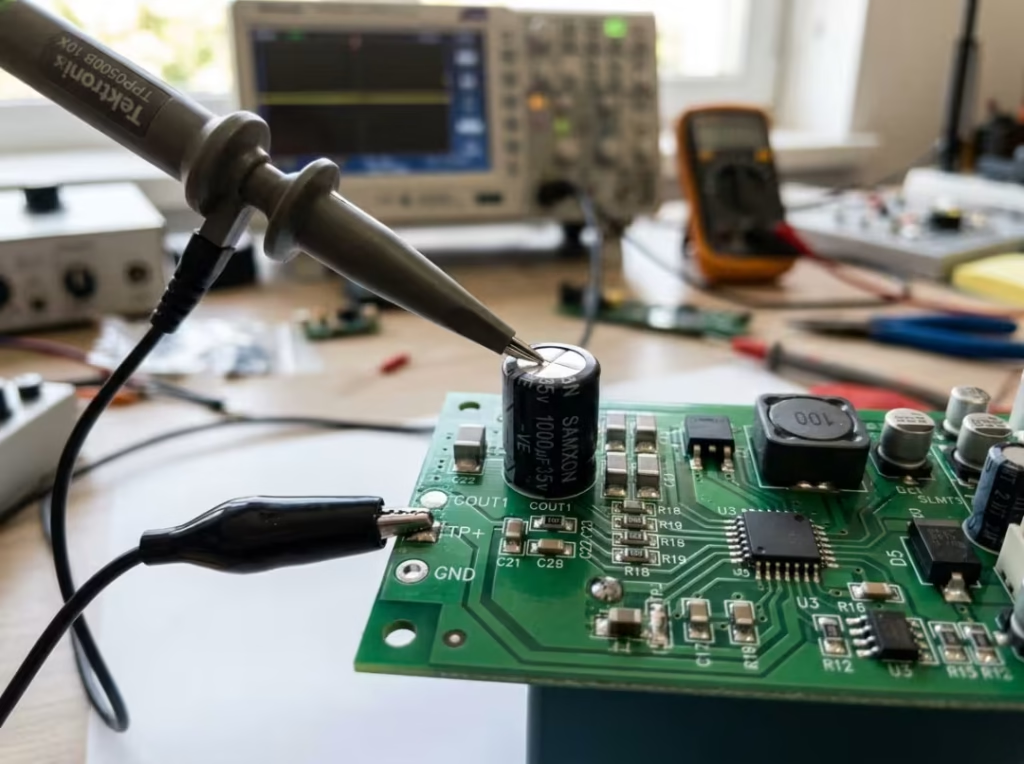
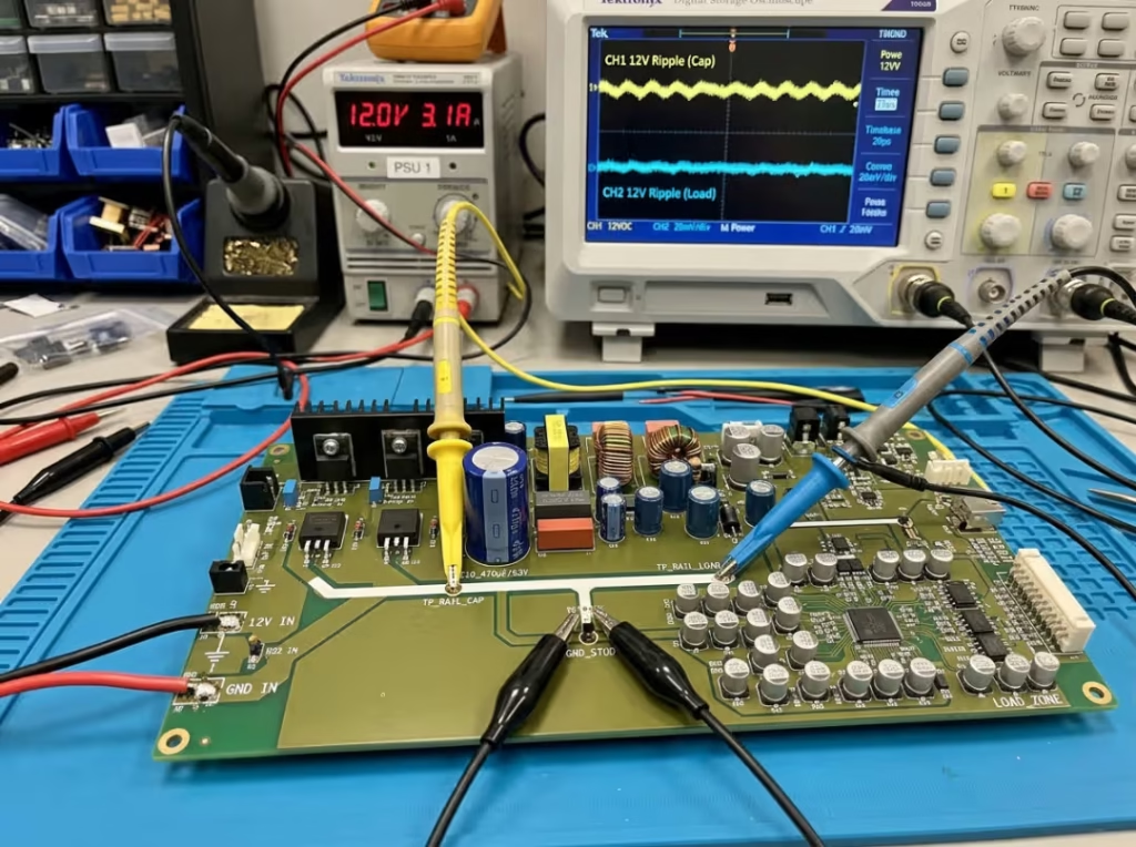
Measuring across the output capacitor terminals shows you what the supply itself is producing — the closest thing to the converter’s own output, and typically where the datasheet figure is taken. Measuring at the load shows you what the downstream circuitry actually receives, after trace resistance, inductance, and return-path currents have done their work.
Both are legitimate measurements. The comparison between them is where the diagnostic value is:
- Clean at the capacitor, noisy at the load — look at trace routing, ground return paths, and layout between the supply and the load, not the converter core itself.
- Noisy at both points — the supply is a more likely suspect.
That one comparison often saves more time than randomly swapping components.
Match scope settings to what you’re actually trying to measure
Settings don’t just improve visibility. They change what ends up in the measurement.
AC coupling blocks the DC level, so you can scale down to millivolt resolution without the trace running off-screen. If AC coupling isn’t available, use DC coupling with vertical offset to bring the trace back into view.
20 MHz bandwidth limit. This isn’t a convenience setting — in many cases it’s part of the measurement specification. Most datasheet ripple figures assume it, because the limit excludes high-frequency content that was never meant to be included in the ripple number. Switch it off only when you’re deliberately characterizing noise and ringing, and be clear with yourself that you’re now measuring something different.
Vertical scale. Aim for the ripple to fill roughly half the screen, typically 10–50 mV/div. Too compressed and you clip the peaks, understating peak-to-peak. Too expanded and the real ripple disappears into the scope’s quantization noise floor.
Timebase. What you capture depends entirely on this. Line-frequency ripple needs milliseconds per division; switching ripple needs microseconds; ringing at switching transitions needs nanoseconds. Capture several cycles rather than one — that’s the only way to confirm the reading reflects steady-state behavior rather than a single event.
Peak detect and hi-res modes. Peak detect catches narrow spikes that normal sample-rate acquisition misses. Hi-res averages within a single acquisition, reducing random noise while preserving the true periodic waveform.
Averaging. Use it carefully. Averaging across many triggers removes random and non-periodic content, which means burst noise and asymmetric ripple can silently disappear from the trace. If you use averaging to clean up the display, you may be averaging away the behavior you most needed to see. Hi-res is usually the better choice for ripple work.
A Practical Ripple Measurement Workflow
With the setup established, the order of measurement matters — mostly because it keeps separate problems from blending into a single confusing number.
Define the operating condition before capturing anything
A ripple number without load, input voltage, and measurement point is only half a result. Before you start:
- Load: measure at no load, typical load, and full rated load. Ripple generally worsens with output current, so full load produces the worst case relevant to compliance.
- Input voltage: when the spec is line-sensitive, test at low, nominal, and high line. Duty-cycle changes in a switching converter shift both ripple amplitude and frequency.
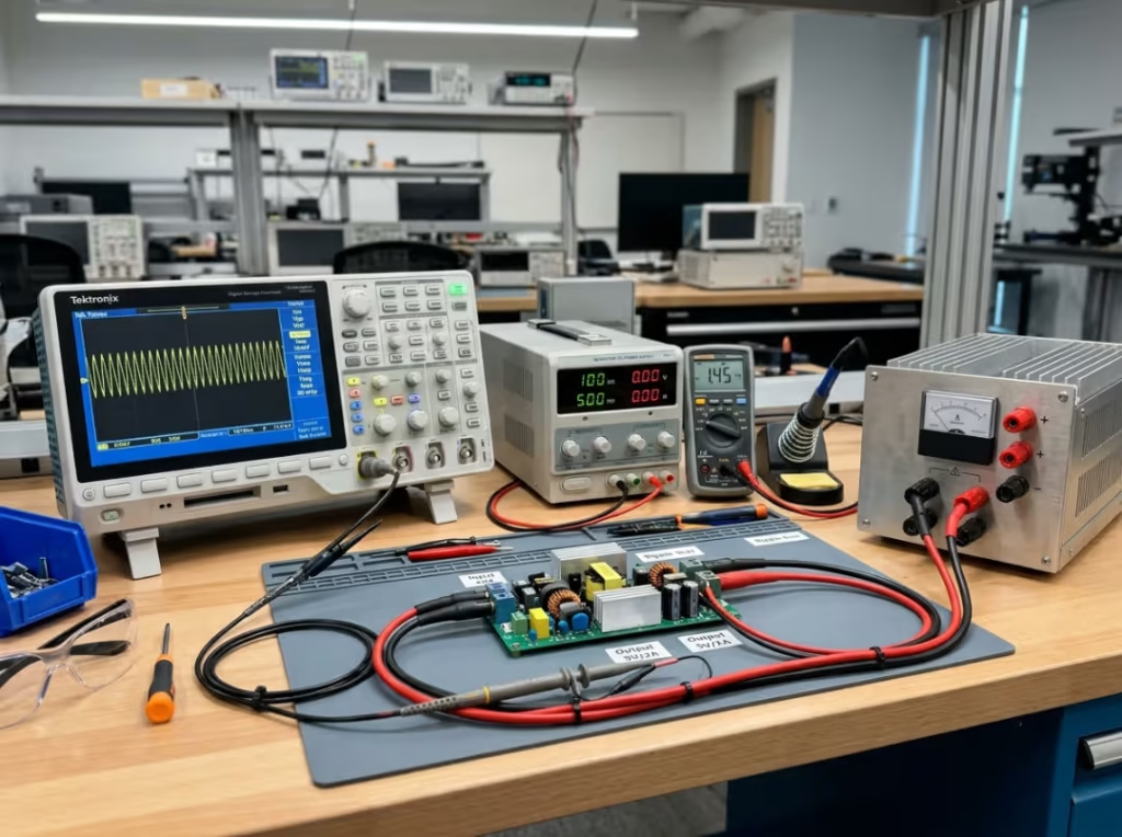
- Load type: use a resistive load bank when possible. Many electronic loads draw current in pulses, which generates voltage spikes across parasitic inductance that aren’t the supply’s contribution. If a reading looks significantly worse under an electronic load, cross-check with resistors before drawing conclusions.
Test the measurement method before testing the device under scrutiny
The fastest path to a trustworthy result is confirming that the setup itself is working. Apply the probe to a rail you already know is clean and well-behaved. If that suddenly looks noisy, the problem is in the probe or scope settings — fix those before touching the device under test.
Capture steady-state ripple first
Start with the number the spec is most likely describing: AC coupling on, 20 MHz limit enabled, short ground path, measurement across the output capacitor at the defined load. Read peak-to-peak across several cycles and note the dominant frequency. Don’t let ringing or transient behavior bleed into this first reading unless the datasheet explicitly includes it.
Then inspect high-frequency noise and switching spikes separately
Once you have the baseline ripple figure, widen the window to see what the bandwidth limit was excluding. Turn off the bandwidth limit, compress the timebase to the 100 ns–1 µs range, and examine what happens around each switching transition. High-frequency spikes and ringing matter for layout and parasitic characterization, but they address a different question than the nominal ripple spec. Label these results separately and don’t combine them with the first measurement.
Characterize transient response only when the application requires it
A rail can pass every steady-state ripple check and still behave badly during a load step. If transient behavior matters to the application, apply a dynamic load step, trigger on the output voltage dip, enable persistence, and record the overshoot, undershoot, and settling time. Treat it as its own measurement against a transient specification — it doesn’t belong in the steady-state ripple figure.
Record what you did, not just what you got
A ripple result is only useful if someone else can reproduce it. That kind of repeatability depends not only on probe technique and scope settings, but also on the broader in-house testing and validation capability behind the measurement process. That means documenting more than the millivolt figure. With every screenshot, record: load, input voltage, measurement point, probe method, coupling mode, bandwidth limit, and timebase. A number without its conditions attached is nearly useless in a design review or compliance audit.
Telling a Bad Reading from a Bad Power Supply
This is where measuring becomes engineering judgment. Plenty of engineers can capture a waveform. Fewer take the next step and ask whether the waveform deserves to be believed.
Signs the reading is probably an artifact
The clearest signal that a measurement is untrustworthy is how easily it changes when the setup changes:
- Peak-to-peak drops sharply when you swap the alligator clip for a ground spring.
- The waveform shifts when you touch or reposition the ground lead.
- The number changes when nearby equipment is switched on or off.
- Large spikes shrink substantially when you enable the 20 MHz bandwidth limit.
- The waveform pattern looks more like environmental pickup than a stable, repeating component locked to the switching frequency.
A power rail doesn’t clean itself up because you held the probe differently. A bad setup does. When small technique changes produce large changes in results, mistrust the technique before mistrusting the supply.
Signs the problem is probably real
A genuine ripple problem tends to hold up under clean measurement conditions:
- The number stays elevated across repeated short-ground measurements.
- It worsens consistently as load increases.
- It reproduces reliably at a specific line or load condition.
- There’s low-frequency oscillation or sustained ringing after load steps — a compensation or loop-stability issue, not a filtering one.
- High-frequency ripple has been gradually climbing, suggesting capacitor aging or rising ESR.
Consistent results across varied conditions are the strongest indication that the circuit, not the probe, is where the problem lives.
Compare two measurement points on the same rail
One of the most efficient diagnostics in ripple work isn’t comparing two supplies — it’s comparing two points on the same rail. If the output capacitor is clean and the load end is noisy, the converter is likely fine, and the issue is downstream: trace routing, ground returns, or cable paths. That distinction can redirect an hours-long component search in a few minutes.
Follow a troubleshooting sequence that avoids wasted effort
When a ripple number looks suspicious, work outward from the measurement before reaching into the schematic:
- Shorten the probe ground and re-measure.
- Toggle the 20 MHz limit and compare with it on versus off.
- Move the measurement point — output capacitor versus load.
- Swap load type — electronic versus resistive.
- Vary input conditions — low, nominal, high line.
- Check output capacitor ESR with an LCR meter.
- Examine loop stability and compensation behavior.
- Inspect PCB layout and ground return routing.
- Verify input bulk capacitance is adequate.
- Consider inductor saturation if you see sharp, current-dependent steps at high load.
The more systematic the order, the less time you spend chasing faults that were never in the converter to begin with.
Interpreting the Result
Peak-to-peak is the primary pass/fail number
For most ripple assessments, peak-to-peak is what decides pass or fail — it directly represents the worst-case voltage excursion the load sees. RMS is useful for estimating noise power and component heating, but it understates narrow spikes. A rail with occasional sharp excursions can post a reassuring RMS figure while exceeding its peak-to-peak limit by a meaningful margin. If the specification is written peak-to-peak, that’s where judgment belongs.
What normal looks like across supply types
Rather than a table of standards, what’s more immediately useful is a rough sense of scale:
- Linear bench supplies: typically a few millivolts peak-to-peak when well filtered. Significantly more suggests ground-loop pickup or an aging filter capacitor.
- Quality switching supplies — including ITE power supplies — commonly land in the 10–50 mV peak-to-peak range at full load.
- ATX and server rails: published limits vary by rail and standard revision, generally in the 50–120 mV range. Verify against the exact version your design targets.
- DC-DC converter modules: often specified at 1% of output voltage or less, sometimes as an absolute millivolt figure. Note whether the datasheet says “ripple” or “ripple and noise” — that distinction changes the pass criterion.
Knowing the right order of magnitude helps you catch both real problems and obviously suspicious measurements before spending time on either.
Use the waveform to narrow down the cause
A pass/fail number is a starting point. The waveform character and the operating condition it appeared under usually say more about the underlying cause:
- High-frequency ripple increasing over time — output capacitor ESR rising, likely aging.
- Low-frequency oscillation or extended ringing after load steps — loop compensation needs attention.
- Noisy at the load but clean at the output capacitor — trace routing, return paths, or downstream layout.
- Ripple amplitude that tracks input voltage — input-side filtering or converter operating point.
- Sharp, load-dependent steps at high current — inductor saturation is worth checking.
The goal isn’t to report that the rail is bad. It’s to know where to look next.
FAQ
Do I really need the 20 MHz bandwidth limit when measuring ripple?
For comparisons against most datasheets and industry standards, yes. Those specs are generally written assuming that limit, and removing it lets in RF noise, switching spikes, and scope input noise that the ripple figure was never meant to include. Remove it only when you’re deliberately characterizing high-frequency noise or ringing — and understand that you’re now measuring something the ripple spec doesn’t cover.
Should I use AC or DC coupling for ripple measurements?
AC coupling for most ripple work. It removes the DC level so you can scale down to millivolts without the trace leaving the screen. When AC coupling isn’t available on a given input, use DC coupling with vertical offset to bring the waveform back into view. The goal is a clear, unclipped view of the AC excursion.
Why does my ripple reading change when I touch the probe ground clip?
Because the measurement loop is picking up noise, and touching the lead changes its geometry. A rail doesn’t change electrically because you moved a probe wire. That sensitivity is a reliable indicator that the reading is reflecting the setup rather than the supply. Shorten the ground path — ground spring or soldered connection — and re-measure.
Can a multimeter accurately measure power supply ripple?
Not in any way you’d rely on for a real decision. A multimeter’s AC mode gives a rough order-of-magnitude estimate at best and shows nothing about waveform shape, frequency content, or the spike structure that distinguishes ripple from noise and transient residue. It’s a rough indicator at best — not a substitute for a scope.
When do I need a differential probe instead of a passive probe?
When the measurement node can’t cleanly share scope ground: floating supplies, high-side switching nodes, or any situation where common-mode voltage or ground loops are a real concern. For standard low-voltage DC rails that reference the same ground as the scope, a correctly connected passive probe is usually sufficient.
Why does my oscilloscope show more ripple than the datasheet specification?
Work through the measurement before doubting the unit. First, confirm the 20 MHz bandwidth limit is active. Then check the probe ground length, the measurement point, and the load condition. The large majority of datasheet mismatches trace back to one of those four items. Only once the measurement is verified as clean should you start questioning the supply itself.
Final Thoughts
Trustworthy ripple measurement begins before the waveform appears — with the ground path, the bandwidth setting, and the choice of measurement point. Get those three things right, and the numbers stop moving around on you.
Most alarming ripple readings turn out to be probe artifacts rather than design failures. Before opening the schematic, shorten the ground, confirm the bandwidth limit, and check that you’re probing the right physical point. Re-measure after each change. Once the method is honest, what’s left on screen is real — and real ripple measurements are genuinely useful: they point to aging capacitors, marginal loop compensation, poor layout decisions, and fault conditions that a multimeter will never find.