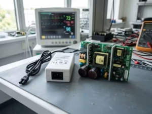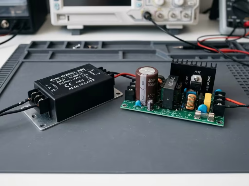
The isolation decision looks binary on paper, but in a real design, it rarely comes down to a single factor. Safety class, grounding scheme, accessible parts, working voltage, EMI behavior, board space, and cost all pull in opposite directions. The right answer depends less on which topology is “better” and more on where a given rail sits in your system and what level of protection the end application demands.
This is a decision guide for engineers, hardware designers, and technical buyers who need to spec the correct topology per rail — not a textbook survey of both. Expect trade-off reasoning, boundary conditions, and failure modes that arise during certification and in field returns.
Isolated vs Non-Isolated Power Supplies: The Short Version
An isolated supply places a galvanic barrier between the input and output, so no direct conductive path connects the two sides. That barrier buys you shock protection, grounding flexibility, and a clear route to compliance in regulated equipment — at the cost of a transformer, extra insulation, and lower efficiency.
A non-isolated supply shares a common connection between input and output. It converts more directly, so it wins on efficiency, size, and cost — exactly what you want for low-voltage, board-level conversion where safety is handled elsewhere in the architecture.
Most robust systems use both: isolation where hazard and grounding demand it, non-isolated conversion everywhere efficiency and density matter. The rest of this guide shows how to make that call, rail by rail.
What Is an Isolated Power Supply?
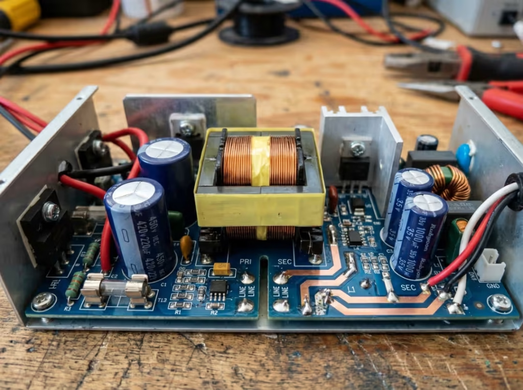
An isolated power supply transfers energy across an insulation barrier rather than through a shared conductor. A transformer or coupled inductor carries energy magnetically, so no metal-to-metal path connects the primary and secondary sides. That separation is what “galvanic isolation” means.
The barrier is defined by hard numbers: isolation withstand voltage (VAC or VDC), creepage, and clearance. These aren’t just safety figures — they ripple through your whole design. They dictate transformer construction, PCB spacing, connector selection, and enclosure layout. Insulation also degrades under moisture, contamination, thermal cycling, and voltage stress, so you derate the barrier and build in margin from the start rather than treating the datasheet rating as a lifetime guarantee.
Choosing isolation isn’t only a safety call. It changes your grounding strategy, adds BOM cost and spacing, and locks in a certification path early. Those downstream consequences are worth understanding before you commit.
What Is a Non-Isolated Power Supply?
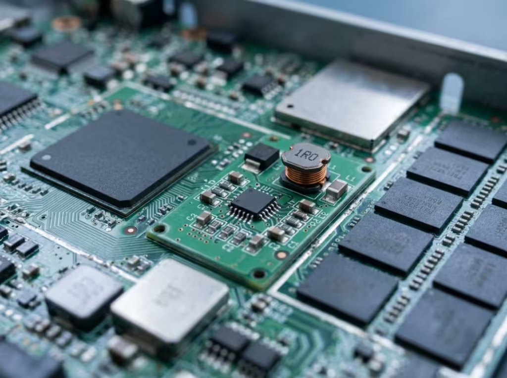
A non-isolated power supply shares a common node — usually ground — between input and output, so current flows through one continuous circuit. Because energy doesn’t cross a barrier, fewer components are involved, and the converter runs more efficiently and takes up less board area.
The clearest examples are board-level. A buck converter stepping a 24 V bus down to 5 V and 3.3 V for logic and processors is non-isolated by design. So is a point-of-load (POL) converter sitting on the secondary side, downstream of an isolated AC-DC front end that already handled mains safety. In both cases, the rail is non-isolated, but the system around it — enclosure, SELV bus, restricted access — keeps users and sensitive circuits protected.
Non-isolated does not mean unsafe. It means the protection lives somewhere other than that specific conversion stage. Get that distinction wrong and you’ll either over-engineer rails that don’t need a barrier or leave a real hazard unaddressed.
Key Differences That Actually Drive the Decision
Weigh these against your application’s constraints. No single factor settles the question on its own.
Safety and Shock Protection
Isolation removes the conductive path between input hazards and accessible outputs, blocking fault currents and surges from reaching anything a user might touch. This matters most when non-experts interact with the product or when output terminals are accessible during normal use. A non-isolated rail can be equally safe — but only when the enclosure, mechanical barriers, or access restrictions carry that burden instead.
Grounding and Ground Loops
This is where isolation earns its keep in instrumentation and data acquisition. A ground loop forms when two devices connect both to each other and to ground through different paths, producing circulating currents that inject noise into sensitive signals. Isolation severs that loop cleanly. It also lets subsystems run on separate ground references, which non-isolated conversion cannot provide.
Efficiency and Thermal Behavior
Non-isolated designs typically achieve 95% efficiency because energy is converted directly. Isolated designs pay a penalty in transformer core loss, copper loss, and leakage inductance. That penalty is acceptable in mains-connected industrial gear but far less attractive in battery-powered products, where every point of efficiency extends runtime, and every watt of loss becomes heat you have to manage.
Size and Power Density
Removing the transformer and its insulation significantly reduces the design. Non-isolated converters often switch faster, allowing smaller inductors and capacitors. On a dense board, that footprint advantage can be decisive. When the enclosure has room, it barely registers.
Cost and BOM Impact
Isolation costs more, and the drivers are predictable: transformers are often custom-wound, insulation systems add material and process steps, and the higher component count raises both BOM and assembly cost. Dropping isolation to save money is smart only when no safety or compliance requirement mandates it — otherwise it’s a false economy that surfaces at certification.
EMI Behavior and Filtering
Isolation is a powerful grounding tool, but it is not a free pass on EMI. The isolation transformer introduces primary-to-secondary parasitic capacitance, which becomes a path for common-mode noise. Your Y-capacitor strategy, switching-node layout, and shielding all shape how much of that noise you contain. Non-isolated designs are more susceptible to conducted noise across the shared connection and rely more heavily on input/output filtering and disciplined PCB layout. Neither topology is inherently quiet — both demand attention to the common-mode path.
Compliance and Certification Impact
Whether isolation is required depends on the end-equipment standard, accessible parts, working voltage, and insulation class — not on a general rule of thumb. Standards define insulation grades (functional, basic, supplementary, double, reinforced) based on the number of layers of protection the application requires. If you’re unsure which standard governs your product, it’s worth sorting that out early; our breakdown of IEC 60950-1 vs IEC 62368-1 covers where that line falls for power adapters. Retrofitting isolation late in a project is expensive, so confirm the requirement before you commit to a transformer and spacing.
Isolated vs Non-Isolated Power Supplies: Quick Comparison
Factor | Isolated | Non-Isolated |
|---|---|---|
Electrical separation | Galvanic isolation | Shared connection |
Safety | Higher | Lower unless protected elsewhere |
Cost | Higher | Lower |
Size | Larger | Smaller |
Efficiency | Usually lower | Usually higher (often >95%) |
EMI / ground loops | Strong grounding control | More vulnerable; needs filtering |
Compliance | Straightforward for regulated markets | Depends on full system design |
Typical topologies | Flyback, forward, LLC | Buck, boost, buck-boost |
Typical use | Medical, industrial, telecom front ends | POL, embedded, low-voltage rails |
When to Use an Isolated Power Supply
Reach for isolation when any of these becomes a hard requirement:
- Users can touch accessible output terminals. Isolation is the cleanest way to keep fault current away from them.
- The end-equipment standard mandates it. Medical and many industrial and telecom categories require galvanic separation.
- The input voltage is hazardous. Mains or high-voltage DC on the primary demands a barrier before that energy reaches accessible circuitry.
- Ground loops threaten signal integrity. Instrumentation, audio, and data acquisition benefit directly.
- Subsystems need independent ground references. Only isolation delivers this.
- Fault containment and surge robustness are critical to reliability. The barrier stops faults from propagating across the boundary.
When one of these is non-negotiable, isolation moves from optional to mandatory, and the rest of the design adapts around it.
When to Use a Non-Isolated Power Supply
Non-isolated conversion is the right call when the system-level context already handles safety:
- You’re converting between low voltages on the board. Bus-to-logic rails don’t need a barrier.
- The rail sits downstream of an isolated stage. System-level isolation is already done; repeating it wastes efficiency and space.
- The circuit is a SELV rail or sits inside inaccessible hardware. No user exposure, no isolation requirement at that stage.
- Efficiency, density, or cost is the top priority. Non-isolated wins on all three.
The trap here is redundant isolation. Adding a barrier where the architecture doesn’t need one increases cost, size, and EMI complexity without improving the end result.
The Architecture Most Real Systems Use: Isolated Front End + Non-Isolated POL
The either/or framing breaks down in practice. Well-built systems combine both topologies deliberately.
A typical layout: an isolated AC-DC front end converts mains and provides the safety barrier, feeding an intermediate 12 V, 24 V, or 48 V distribution bus. From there, non-isolated POL converters step that bus down to the specific voltages each load needs — right next to the processor, FPGA, or memory. You get isolation exactly once, where it protects the user and breaks ground loops, and efficient direct conversion everywhere else.
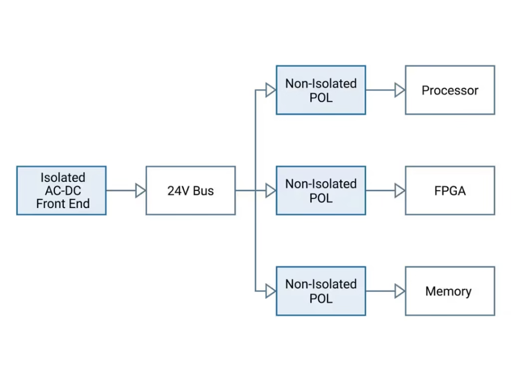
This is the pattern that trips up engineers who think in absolutes. The secondary-side POL rails are non-isolated by design — the front end already provides isolation. The real judgment call isn’t “isolated or not” for the whole system; it’s identifying the single boundary where the barrier belongs and keeping every downstream rail lean.
Isolated vs Non-Isolated DC-DC Converters
The topology you pick reflects the same isolation decision, one rail at a time.
Isolated DC-DC topologies move energy through a transformer:
- Flyback — simple and low-cost, well suited to lower power (roughly up to 100 W). It stores energy in the transformer during the on-time and releases it in the next switching phase.
- Forward — better for medium power, transferring energy directly during the on-time for improved efficiency under load.
- LLC resonant — the choice for higher-power, high-efficiency designs where soft switching cuts losses.
Non-isolated DC-DC topologies convert directly:
- Buck — steps voltage down; the workhorse for POL rails feeding logic and processors.
- Boost — steps voltage up, common in battery-powered and LED-driver applications.
- Buck-boost — handles inputs that swing above and below the output, such as a battery discharging through its full range.
Choose isolated when you need the barrier, a broken ground loop, separate references, or a large step ratio a transformer handles gracefully. Choose non-isolated when efficiency, size, and cost dominate and isolation adds nothing at that stage.
Compliance and Standards: Where Designs Actually Fail
Certification failures rarely come from picking the wrong topology outright. They come from misreading how isolation interacts with the full system.
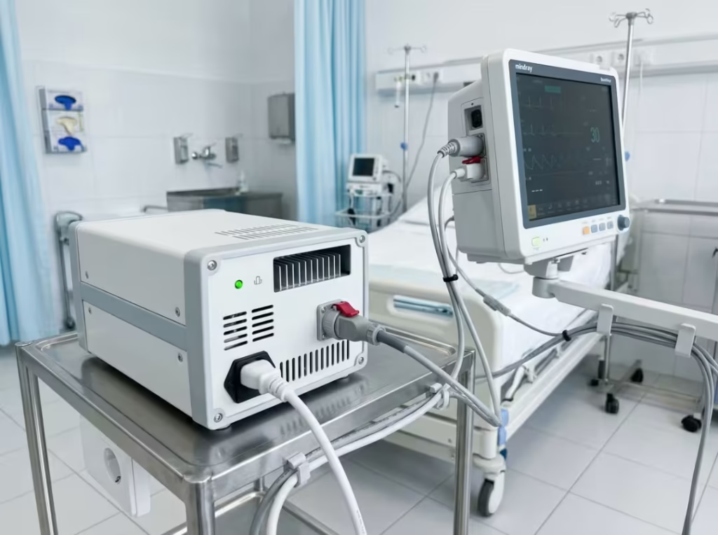
Two points cause the most trouble. First, module-level isolation does not guarantee end-product compliance. A supply rated for a given isolation voltage still leaves you responsible for system leakage current, creepage and clearance across the whole board, enclosure design, and — in medical equipment — the classification of applied parts. Second, leakage current is a budget, not a checkbox. Every path contributes, and medical designs adhere to strict limits that the IEC 60601 standard enforces rigorously.
For patient-connected equipment, the requirements get stricter still. CF-rated applied parts demand the lowest leakage and the most robust isolation, and the design methods — and common failure points — are specific enough to warrant close attention; our detailed look at CF patient leakage isolation is worth reviewing before you finalize any medical rail.
For IT, networking, and AV equipment, IEC 62368-1 now governs, having replaced IEC 60950-1. The insulation grade you need — from functional through reinforced — depends on the working voltage and the protection the application requires. Confirm the governing standard before finalizing a schematic; it constrains transformer selection, spacing, and enclosure design further upstream than most teams expect.
How to Choose: A Rail-by-Rail Selection Framework
Run every rail through this sequence — not just the system as a whole.
- Safety first. Can a user contact this rail’s output? Does it carry hazardous voltage? If yes, lean toward isolation.
- Standard. Does IEC 60601, IEC 62368-1, or another end-equipment standard mandate isolation here? If so, that decides it.
- Voltage and grounding. Are you crossing from a hazardous input, or do subsystems need separate references? Isolation helps.
- Noise. Are ground loops or signal integrity in play? Isolation is a strong tool.
- Size and efficiency. Is space tight or runtime critical? Non-isolated likely wins — especially downstream of an isolated front end.
- Form factor. Match packaging to enclosure and thermal requirements; the trade-offs covered in our open-frame vs. enclosed power supplies guide matter as much as the topology.
- Cost. With no safety or compliance driver, non-isolated is the economical choice.
The discipline is running this per rail. A system almost never wants one answer across the board.
Common Selection Mistakes
These are the pitfalls that turn into respins and field returns:
- Reading isolation voltage without checking working voltage, creepage, and clearance. The withstand number alone tells you little about real-world spacing under pollution degree and altitude.
- Treating a module’s isolation rating as end-product compliance. The datasheet covers the module. Your system still has leakage, board-level spacing, and enclosure issues.
- Ignoring the leakage-current budget. In medical designs especially, every path contributes, and a late discovery here forces redesign.
- Overlooking reference strategy in multi-board systems. Shared and floating grounds, carelessly mixed, produce the kind of noise that isolation would have prevented.
- Isolating twice. Repeating isolation after an isolated front end burns efficiency, space, and cost for no safety gain.
- Confusing functional isolation with safety isolation. They serve different purposes and meet different requirements — one cannot substitute for the other.
How to Tell Whether a Power Supply Is Isolated
If you inherit a supply with no clear documentation, verify before you trust it:
- Measure between input and output. With the unit unpowered, check for continuity or a low-resistance path between an input reference point and an output reference point. A conductive path suggests it is not isolated. Never probe a live high-voltage supply.
- Read the schematic. A transformer between primary and secondary confirms isolation.
- Check with the manufacturer. Have the model number ready, and confirm the isolation rating directly from the datasheet.
- Inspect the label. Look for the double-insulation symbol (a square within a square), an isolation-voltage rating, or shock-hazard warnings.
Until you’ve confirmed isolation, treat the supply as non-isolated and apply every relevant precaution.
Frequently Asked Questions
Is an isolated power supply safer?
Usually, yes — it removes the direct path between the input and the output, blocking fault currents from reaching accessible outputs. That said, a non-isolated supply is equally safe when the enclosure, barriers, and access controls handle user protection at the system level.
Is a non-isolated power supply more efficient?
Typically. Without a transformer, conversion is more direct and often exceeds 95%. Isolated designs give up some efficiency to core and copper losses in the magnetic element.
Do all AC-DC power supplies need isolation?
No. Many are isolated for safety, particularly when users can touch the output or a standard requires it. Fully enclosed, low-risk designs can use non-isolated conversion when system-level protection is sufficient.
Is galvanic isolation the same as transformer isolation?
Galvanic isolation is the broader concept — no direct conductive path between two circuits. A transformer is the most common way to achieve it, but coupled inductors and capacitive methods also qualify.
When should I use an isolated DC-DC converter?
When you need galvanic separation, must break a ground loop, require separate ground references, face hazardous input voltages, or need a large step ratio that a transformer handles more gracefully than a direct topology.
Final Thoughts
The isolated-versus-non-isolated question resolves clearly once you stop treating it as a system-wide verdict and start treating it as a per-rail engineering call. Isolation delivers safety, ground-loop control, and a clear compliance path where the application demands it. Non-isolated conversion delivers efficiency, density, and lower cost everywhere else. The strongest architectures use both — one barrier at the front end, lean POL rails downstream.
Work through the seven-step framework for each rail in your design, confirm the governing standard, and nail down your grounding and leakage budgets before you commit to hardware. That discipline is what keeps a project off the respin treadmill and on track for certification.
If you’re specifying supplies for medical, industrial, or communication equipment, our engineering team can review your isolation strategy, help you map the right topology to each rail, and flag compliance gaps before they become costly. Get in touch, and we’ll take a look.