A cardiac monitor clears every bench check. The power supply datasheet shows the correct isolation figures, the enclosure passes the touch-leakage test, and the team schedules certification. Then the single-fault patient leakage test comes back at 62µA. The applied part contacts the bloodstream, so the limit is 50µA—not the 500µA everyone had been mentally working against. Now the fix touches the power architecture, and the launch slips a quarter.
That scenario plays out more often than most teams admit. The technical work was competent. The classification decision was made too late.
CF (Cardiac Floating) isolation is the strictest applied-part category in IEC 60601-1, and it differs from BF in ways that affect your power architecture, component spacing, and certification path. This walks through when CF actually applies, how the standard drives your design, where these designs break down in testing, and how to select a power supply that gives you margin instead of surprises.
When CF Isolation Is Actually Required
The trigger is physical, not electrical. If an applied part creates a conductive path to the heart or the bloodstream, the device must be evaluated against CF requirements from the start. That includes:
- Dialysis machines
- Electrosurgical instruments
- Cardiac monitors and catheter-based equipment
- Any device with a direct electrical route to the heart
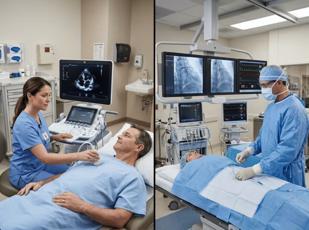
BF can be sufficient when the applied part contacts only the body surface—for example, an ultrasound probe, a blood pressure cuff, or an incubator. The line between “touches the skin” and “touches the bloodstream” is where the classification changes, and it changes hard: CF limits are roughly ten times tighter.
Some CF and BF parts also carry a separate defibrillation-proof rating when the device may be in use while a defibrillator fires. That rating sits alongside the CF classification; it does not replace it.
Design judgment: Make this call at the concept stage. The expensive version of this mistake is discovering during certification that a BF architecture needed to be CF. The safer assumption, when the application is life-critical and heart contact is even a possibility, is to design to CF and build in a margin.
BF vs CF: What the Difference Means for Design Decisions
On a datasheet, BF and CF look similar. Both are floating—neither is tied to earth ground—so the architecture appears interchangeable. It isn’t. The difference lives in where the part contacts the patient and how much leakage the standard tolerates.
Dimension | Type BF | Type CF |
|---|---|---|
Patient contact | Conductive contact with the body surface | Direct contact with the heart or bloodstream |
Patient leakage (normal) | 100µA | 10µA |
Patient leakage (single-fault) | 500µA | 50µA |
Output-to-ground isolation | 1,500 VAC | 1,500 VAC (with tighter overall system design) |
Grounded | No (floating) | No (floating) |
Typical use | Ultrasound, BP cuffs, incubators | Dialysis, surgical tools, cardiac devices |
Stringency | Moderate | Highest |
The practical mistake is not misunderstanding the terminology. It is assuming a BF-rated architecture can be stretched into a CF application by tightening a few components. The 10µA normal limit forces decisions about transformer construction, Y-capacitor values, and grounding topology that a BF design never had to confront.
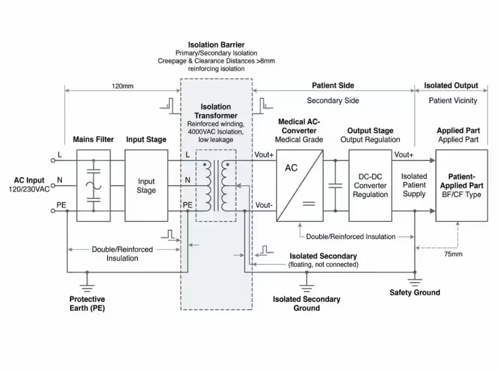
Design judgment: Treat CF as a different starting point, not a stricter version of BF. If the applied part reaches the bloodstream, the question is no longer whether BF can be optimized—it’s how the CF budget is allocated across the whole system.
IEC 60601-1 Requirements That Drive CF Design
IEC 60601-1 governs the safety and essential performance of medical electrical equipment. For CF work, three areas of the standard do most of the shaping: means of protection, isolation voltages, and leakage limits.
MOP, MOPP, and MOOP
Every medical device needs two means of protection (MOP)—two independent barriers between hazardous circuitry and anyone who might touch the patient or the operator. MOP splits into two categories depending on who is being protected:
- MOPP (Means of Patient Protection) — the barrier protecting the patient
- MOOP (Means of Operator Protection) — the barrier protecting the operator
CF designs demand the highest level of patient protection, which means MOPP requirements call for greater spacing and insulation than MOOP at the same voltage. That distinction matters when you’re budgeting creepage and clearance on a crowded board, and it’s worth reviewing the MOOP vs MOPP split before you lock the layout. Isolation itself comes from a combination of protective earth, insulation, and adequate creepage and clearance distances.
Isolation Voltage Requirements
For a CF-capable power supply, the standard sets these levels:
- Input-to-Output: 4,000 VAC or 2 MOPP
- Input-to-Ground: 1,500 VAC or 1 MOPP
- Output-to-Ground: 1,500 VAC
Leakage limits also differ between AC and DC, so both need to be checked against your actual operating conditions rather than a single nominal figure.
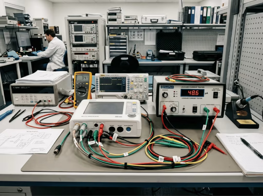
Design judgment: For CF applications, passing certification is rarely about a single headline-grabbing number. The real challenge is whether the entire system stays inside the leakage limits under both normal and single-fault conditions. A compliant power supply is a starting condition, not a guarantee.
Where CF Designs Fail in Testing
Most CF failures don’t come from a bad component. They come from system-level oversights that stay invisible until the test lab applies fault conditions. A few patterns show up repeatedly.
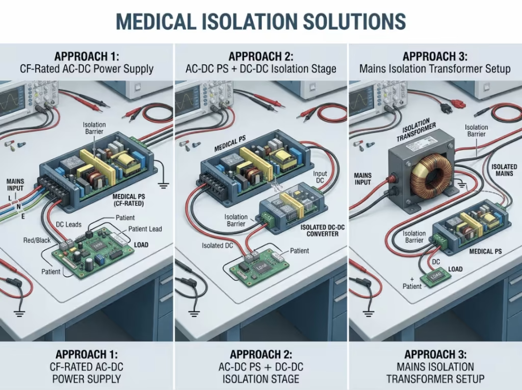
Trusting the datasheet instead of the system budget. A power supply rated for CF-level leakage tells you what that supply contributes—not what the assembled device produces. Downstream modules, cabling, and filtering all add to the total. The failure usually appears when the individual parts each look fine but, when stacked together, exceed 10µA.
Treating a BF solution as CF. A design carried over from a BF product often passes normal-condition testing and then fails single-fault testing because the 50µA ceiling leaves no room for the leakage paths that a BF architecture quietly tolerated.
Ignoring the output-to-ground path. Teams focus on input-to-output isolation and overlook output-to-ground leakage, which becomes significant once the device is grounded through connected equipment.
Skipping single-fault verification. This is where designs most often run into trouble. A device can be comfortably inside limits under normal conditions and blow past them the moment a fault is introduced. Verifying only the normal case gives false confidence.
Testing under conditions that don’t match certification. Worst-case input voltage—typically 264 VAC for a universal-input design—results in higher leakage than a nominal bench setup. A design validated at 230 VAC can still fail at the certified worst-case condition.
Design judgment: Verify leakage as a complete system, under both normal and single-fault conditions, at worst-case input. That single discipline separates a design that passes on first submission from one that gets sent back.
Three Methods to Achieve CF Isolation: A Decision Framework
There are three established routes to CF compliance. The right one depends on power level, form factor, and the level of system complexity you’re willing to carry. Each also has a failure mode that engineers tend to underestimate.
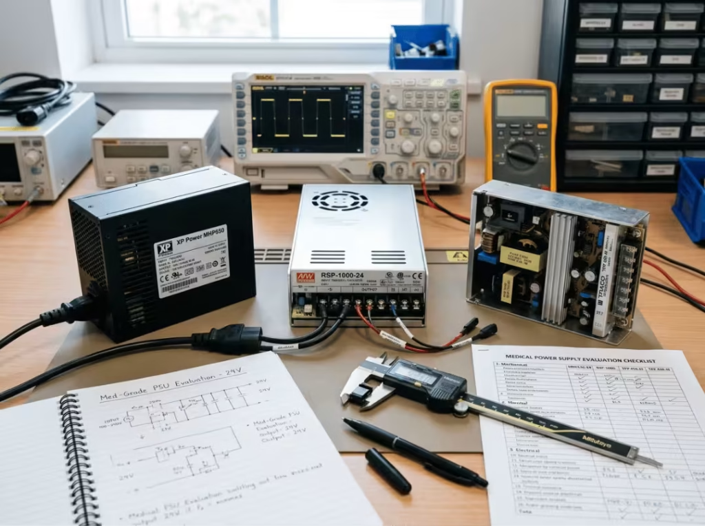
Method 1 — CF-Rated Medical Power Supply
Use a supply purpose-built and NRTL-certified for CF, with the required spacing, patient leakage performance, and isolation already engineered in.
This provides the cleanest architecture, optimal size and efficiency, and the clearest certification path. It may cost more upfront than a general-purpose supply, and for most life-critical CF applications, that premium buys back time and risk.
Commonly underestimated: engineers assume a certified CF supply alone guarantees a system pass. It doesn’t—the rest of the device still has to stay inside the budget.
Method 2 — Additional DC/DC Isolation Stage
Add a medically approved DC/DC converter as a second isolation stage after a standard medical supply. This can reduce patient leakage to single-digit microamps—often around 2 µA—and suits both BF and CF.
The constraint is power: DC/DC converters may not provide the power higher-power devices need, and the extra stage adds cost and board space. The best fit is for lower-power devices where a compact secondary stage fits cleanly.
Commonly underestimated: leakage improves, but thermal load, footprint, and EMC complexity all increase. Solving the leakage number can create three new problems.
Method 3 — Isolation Transformer
Place an isolation transformer between the mains input and the power supply. It provides a genuine additional barrier from the AC input.
The cost is physical: transformers are large and heavy—often bigger than the supply itself—and they introduce efficiency losses. This route mostly makes sense for legacy designs or situations where the supply can’t be changed.
Commonly underestimated: it solves one barrier problem, not the whole system leakage budget. The output-to-ground path and downstream stacking are still yours to manage.
Design judgment: In practice, the best solution is usually the one that reduces system complexity, not the one that looks cheapest at the component level. For most new CF designs, a purpose-built CF-rated supply wins on the axes that actually matter over the life of a product.
How to Choose the Right Power Supply for CF Applications
Selecting a supply for a CF device is a systems task, not a line-item purchase. A workable sequence:
- Confirm the applied-part classification (B, BF, or CF) before anything else. Everything downstream depends on this.
- Check required isolation against that classification—output-to-ground, input-to-output, and the MOPP levels that apply.
- Build a full system leakage budget. Evaluate the whole device, not one component. This is the step that prevents most late surprises.
- Decide whether a second isolation stage is needed to reach your leakage target, weighing the thermal and space cost.
- Verify power, size, and efficiency fit the product form factor.
- Select an NRTL-certified CF-rated supply for the cleanest compliance path.
A BF supply can work for surface-contact devices. For heart-contact applications, the supply should be CF-rated for maximum patient margin. When you’re comparing options, look at medical-grade power supplies that publish leakage data at worst-case input rather than nominal conditions—that data is what your compliance case rests on.
Design judgment: Before you shortlist any supply, build a system-level leakage budget table. If a candidate leaves no headroom below 10µA in that table, it isn’t the right supply, regardless of what its own datasheet claims.
CF Isolation Design Checklist
A working checklist to keep the design honest through development:
- Confirm the applied part is classified as CF
- Verify patient leakage limits: 10µA normal / 50µA single-fault
- Confirm output-to-ground isolation (1,500 VAC)
- Verify input-to-output (4,000 VAC / 2 MOPP) and input-to-ground (1,500 VAC / 1 MOPP)
- Build and review the full system leakage budget
- Decide whether a secondary DC/DC stage is needed
- Test under both normal and single-fault conditions, at worst-case input
- Confirm whether a defibrillation-proof rating is required
- Document all IEC 60601-1 test assumptions and operating conditions
- Select an NRTL-certified CF-rated power supply
FAQ
Does a 2 MOPP power supply automatically make the device CF compliant?
No. 2 MOPP describes the isolation barrier between input and output—it’s a necessary condition for CF, not a sufficient one. CF compliance depends on the entire device remaining within the 10µA/50µA patient leakage limits under normal and single-fault conditions. A 2 MOPP supply can still land in a device that fails CF testing once downstream leakage and grounding paths are added in.
Is CF classification determined by the power supply or by the applied part?
By the applied part. The classification follows where the device contacts the patient—heart or bloodstream contact means CF. The power supply is then selected to support that classification. Engineers sometimes reason backward from a supply’s rating, but the applied part sets the requirement, and the power architecture has to meet it.
Can a BF supply be used in a CF device if additional isolation is added?
Sometimes, but it’s the harder path. A BF supply paired with a medically approved DC/DC isolation stage can reach CF-level leakage, and that combination is legitimate for lower-power devices. The trade-off is added cost, board space, thermal load, and EMC complexity. For most designs, a dedicated CF-rated supply gets you there with less system risk than retrofitting isolation onto a BF supply.
Why do CF designs pass normal testing but fail single-fault?
Because single-fault applies a component or insulation failure and then re-measures leakage. A design with little headroom under normal conditions has nothing left when a fault path opens. The 50µA single-fault ceiling is tight, and it’s the condition that exposes optimistic leakage budgets.
Conclusion
CF patient leakage isolation is a system-level engineering problem, not a component selection. It starts with getting the classification right at the concept stage, runs through the IEC 60601-1 isolation requirements, and ends with verification under both normal and single-fault conditions at worst-case input conditions. Skip any of those and the design carries risk into certification.
For most life-critical, heart-contact applications, an NRTL-certified CF-rated power supply gives the best balance of leakage margin, power, size, and efficiency—and it keeps the certification path clean.
If you’re specifying a supply for a CF device, start with the classification and leakage budget, then incorporate global compliance considerations for the markets you’re targeting. Talk to our engineering team early if you want a second set of eyes on your isolation design before it’s locked—that’s the cheapest point in the project to catch a problem.