
Quick answer: To install an open-frame AC-DC power supply safely, mount it inside a protective enclosure on metal standoffs, maintain IEC 62368-1 creepage and clearance distances (typically 3–4 mm to earthed metal in Class I systems), connect protective earth and EMC ground points, provide adequate convection or forced-air cooling, and verify component temperatures and output voltage before sealing the enclosure.
Open frame AC-DC power supplies are the workhorses of embedded and industrial design. They’re compact, cost-effective, and efficient—but because they ship as a bare, populated PCB, the system designer is responsible for safety, cooling, and electromagnetic compatibility. Get the installation right, and you’ll have a reliable, long-lived power stage. Get it wrong, and you risk premature failure, EMC test failures, or a serious shock hazard.
This guide walks equipment designers, OEM engineers, and system integrators through the full installation process. You’ll learn how to handle open-frame power supply mounting, wiring, grounding, and cooling, and how to correctly apply IEC 62368-1 creepage and clearance requirements. We’ll also cover common mistakes, a comparison against enclosed and DIN rail units, and a final checklist to run before you close the enclosure.
What Is an Open Frame AC-DC Power Supply?
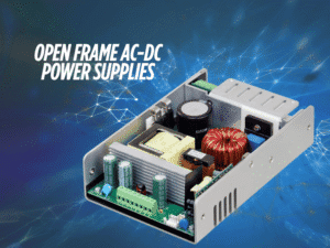
An open-frame AC-DC power supply is a component-level converter supplied as a populated printed circuit board with no protective housing. The end-equipment enclosure provides the physical, electrical, and environmental protection that a standalone product would normally include. This construction reduces cost, weight, and footprint—which is why open frame designs dominate space-constrained applications.

How open frame differs from enclosed and DIN rail power supplies
An enclosed power supply includes a metal or plastic case that provides mechanical protection, partial EMI shielding, and defined safety spacings out of the box. A DIN rail power supply is built for control cabinets, clipping onto a standard 35 mm rail with screw terminals for fast field wiring.
An open frame unit offers none of those conveniences. It trades them for higher power density and lower cost, on the condition that the host enclosure supplies the missing protection. That trade-off shifts more engineering responsibility onto the integrator.
When open-frame power supplies are the right choice
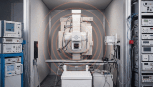
Choose an open frame power supply when board space and cost matter more than installation convenience, and when your product already has a suitable enclosure. Typical applications include medical devices, industrial automation, test instruments, and embedded controllers. If you need fast field servicing or cabinet-mount wiring instead, an enclosed or DIN rail unit is usually the better fit.
One critical point: open-frame supplies are certified as components, not as finished products. Even when a unit carries IEC 62368-1 or IEC 60601-1 approval, end-product compliance remains the system designer’s responsibility. The certification only holds when the supply is installed within the conditions defined in its datasheet.
Before You Install: Safety and Planning Checklist
Planning prevents the last-minute spacing and thermal problems that surface during compliance testing. Work through this checklist before any hardware goes into the enclosure:
- Review the datasheet thoroughly. Note the defined mounting points, ground connections, key component temperatures, and rated service life.
- Confirm input range and output rating. Verify that the supply handles your mains voltage range and that the output rating matches your load with an adequate margin.
- Identify the cooling method. Determine whether the datasheet power rating assumes convection cooling, forced air, or both.
- Verify enclosure protection. Confirm your enclosure provides shock protection, fire containment, and the ingress protection your environment demands.
- Check creepage and clearance. Plan the spacing between live parts and earthed metal in line with IEC 62368-1.
- Plan grounding and cable routing. Identify safety and EMC ground points, and map input and output cable paths to keep them separated.
Step-by-Step Open Frame Power Supply Installation
Step 1: Choose the mounting location and board orientation
Select a location with room for airflow on all sides and away from heat-sensitive components. Orientation matters: convection-cooled units rely on rising warm air, so the datasheet’s recommended orientation often assumes a specific board position. Keep input and output sections accessible for wiring, and position the supply so heat from adjacent components doesn’t preheat its critical parts.
Step 2: Maintain creepage and clearance distances (IEC 62368-1)
Creepage is the shortest path between two conductors measured along an insulating surface, while clearance is the shortest path through air. Both must be observed on all faces of the power supply relative to the enclosure and any nearby conductive parts.
In a Class I system, maintain 3 to 4 mm between any primary (hazardous voltage) part and earthed metal, depending on whether the application is industrial or medical. Class II designs in metal enclosures may require larger distances, though these units are often used in non-conductive enclosures instead. Under IEC 62368-1, the required spacing depends on working voltage, pollution degree, and insulation type—reinforced insulation requires roughly twice the creepage of basic insulation. Where spacing is tight, add insulating barriers around the assembly.
Step 3: Use the right standoffs and mounting hardware
Mount the PCB on metal standoffs that match the supply’s mounting holes. Metal standoffs serve a dual purpose: they hold the board securely and provide a low-impedance ground path that improves EMC performance. The optimal approach is to mount the open-frame supply on a metal plate, which provides the output common-mode filter capacitors with a low-impedance, low-parasitic connection to ground. The plate doesn’t need to connect to anything else to deliver this benefit.
Use the standoff height specified or implied by the datasheet to preserve clearance beneath the board. Never over-torque fasteners, as this can crack the PCB or stress solder joints.
Step 4: Connect the AC input, DC output, and protective earth
Wire the AC input, DC output, and protective earth according to the datasheet’s terminal or connector assignments. In a Class I system, the safety ground connection is an integral part of the supply’s protection and must be securely bonded to the system safety ground—typically through a mounting hole, fastening tab, or the input connector.
Open-frame supplies often require two, and sometimes three, ground connections. One is the input-side safety ground; the others, on the secondary side, connect the output common-mode filter capacitors to ground. All identified points must be connected for both safety and EMC compliance. Choose a wire gauge based on the rated current with an appropriate margin, and keep connections tight to avoid resistive heating.
Step 5: Plan airflow and thermal derating (convection vs. forced air)
The datasheet power rating reflects a specific cooling condition. A convection rating assumes free air movement, while a higher forced-air rating depends on a defined airflow across the board. If your enclosure restricts airflow, you must apply thermal derating—reducing the load you draw from the supply to keep components within their limits.
Confirm which cooling regime your design uses and size your fan or vents accordingly. Forced-air cooling delivers more usable power from the same board, but only if airflow actually reaches the hottest components.
Step 6: Route cables to reduce EMI and heat buildup
Keep input and output wiring physically separated, and route both away from the power supply where practical. This limits noise coupling and prevents cable bundles from trapping heat near the board. Twist or shield noisy conductors where needed, and avoid running signal cables parallel to the AC input. Tidy routing improves both EMI performance and thermal behavior.
Step 7: Perform first power-up and output voltage testing
Before connecting the full load, power up the supply and confirm the output voltage matches the datasheet specification. Then run the complete end-product under worst-case conditions—maximum load, maximum ambient temperature, and minimum airflow—and measure the temperature of the critical components identified in the datasheet. If any approaches or exceeds its rating, improve cooling or relocate the supply before proceeding.
Open Frame Power Supply Cooling Requirements
Convection vs. forced-air cooling
Convection cooling relies on natural air movement and is well-suited to lower-power designs or generously vented enclosures. Forced-air cooling uses a fan to push air across the board, unlocking the supply’s higher-rated output. The right choice depends on your power demand, enclosure volume, and acoustic constraints.
Thermal derating
Every open-frame supply has a maximum operating temperature beyond which its output capability drops. When ambient temperature rises or airflow falls, derate the load accordingly. Datasheets commonly provide an estimated service life tied to the temperature of key electrolytic capacitors—running hot shortens that life dramatically, even when performance seems fine at first.
Sealed enclosure considerations
A sealed enclosure blocks airflow, so convection and forced-air cooling are unavailable. In these cases, you must conduct heat out through the enclosure walls, add a heatsink, and apply significant derating. Always validate component temperatures inside the sealed assembly, since trapped heat is the leading cause of premature failure.
Grounding, Shielding, and EMI Best Practices
Protective earth and chassis bonding
In Class I systems, protective earth is a safety-critical connection, not an optional one. Bond the supply firmly to the chassis ground using a secure, low-impedance connection. A metal mounting plate or enclosure provides an ideal bonding surface and supports common-mode noise suppression.
Shield termination
Common-mode noise is the component that travels through metal cases and frames. Terminate cable shields properly and connect the supply’s designated EMC ground points—often through the mounting holes—to give that noise a controlled return path. In plastic enclosures, you’ll need to deliberately link these points together, since the enclosure can’t do it for you.
Ferrite beads and input filters
Where conducted emissions remain above limits, ferrite beads on input or output cables and supplementary input filtering can help reflect or absorb noise. Combine these measures with good grounding and cable separation rather than relying on any single technique.
Common Open Frame Power Supply Installation Mistakes to Avoid
- Ignoring creepage and clearance on every face. Spacing must be observed on all sides, not just the obvious one.
- Skipping secondary-side EMC ground points. Connecting only the safety ground often causes EMC test failures.
- Trusting the datasheet rating without thermal validation. Always measure the temperatures of critical components in your actual enclosure.
- Using an open frame supply without an enclosure. These boards are not meant to operate exposed; doing so creates a shock and contamination hazard.
- Routing input and output cables together. This couple’s noise and traps heat near the board.
- Over-torquing mounting hardware. Excess force can crack the PCB or damage solder joints.
- Assuming component certification covers the end product. End-product compliance is always the integrator’s responsibility.
Open Frame vs. Enclosed vs. DIN Rail Power Supplies
Factor | Open Frame | Enclosed | DIN Rail |
|---|---|---|---|
Protection | Relies on the host enclosure | Integrated case | Integrated case |
EMI shielding | Minimal—needs system design | Partial, built-in | Partial, built-in |
Power density | Highest | Moderate | Moderate |
Cost | Lowest | Mid-range | Higher |
Installation effort | Highest—full integration required | Moderate | Lowest—clips to rail |
Field serviceability | Low | Moderate | High |
Best for | Embedded medical instruments | General-purpose products | Control cabinets, automation |
Choose an open frame if cost and power density matter most, and you control the enclosure design. Choose enclosed if you want defined safety spacings and partial shielding with less integration work. Choose DIN rail if fast cabinet wiring and field servicing are priorities.
Open Frame Power Supply Installation FAQ
How much clearance does an open-frame power supply need?
In a Class I system, maintain 3-4 mm clearance between any primary part and earthed metal, depending on whether the application is industrial or medical. Under IEC 62368-1, the exact creepage and clearance values depend on working voltage, pollution degree, and insulation type, with reinforced insulation requiring roughly double the creepage of basic insulation. Always verify against the datasheet and the relevant standard for your product.
Can an open-frame power supply be installed in a sealed enclosure?
Yes, but a sealed enclosure prevents convection and forced-air cooling, so you must conduct heat out through the walls or a heatsink and apply significant thermal derating. Validate the temperature of critical components inside the sealed assembly before finalizing the design.
Do open-frame power supplies need protective earth grounding?
Class I open-frame power supplies require protective earth grounding as an integral part of their safety system. The safety ground must be securely bonded to the system safety ground. Many units also need additional secondary-side ground connections for EMC, and all designated points must be connected.
Why does an open-frame power supply make a high-pitched noise?
A high-pitched noise usually comes from magnetic components such as transformers or inductors vibrating at the switching frequency, sometimes worse under light load or certain duty cycles. It’s often benign, but if it’s accompanied by overheating or unstable output, check loading, mounting, and component temperatures.
Can I mount an open-frame power supply horizontally?
Mounting orientation affects convection cooling, so follow the datasheet’s recommended orientation. If you mount it differently, verify that airflow still reaches the critical components and confirm temperatures under worst-case conditions, applying derating if needed.
What wire gauge should I use for an open-frame power supply?
Select a wire gauge based on the rated input and output current with an appropriate margin, following the datasheet and applicable wiring standards. Undersized wire causes resistive heating and voltage drop, so size conductors for the full load plus headroom and keep terminations tight.
Final Checklist Before Closing the Enclosure
Run through these items before you seal the assembly:
- Creepage and clearance verified on all faces per IEC 62368-1
- PCB mounted on correct standoffs without over-torqued fasteners
- Protective earth connected and securely bonded (Class I)
- All secondary-side EMC ground points are connected
- Input and output cables are separated and routed away from the board
- Cooling method confirmed, and airflow validated
- Thermal derating is applied where airflow is restricted
- Output voltage verified against the datasheet
- Critical component temperatures measured under worst-case load
- End-product compliance responsibilities documented
A safe, reliable open-frame installation comes down to disciplined planning: proper spacing, solid grounding, validated cooling, and real-world thermal testing. Treat the datasheet as your specification, confirm temperatures in the actual enclosure, and remember that component-level certification never replaces end-product compliance. With those fundamentals in place, your open-frame power supply will deliver dependable performance throughout its full rated service life.