A plant technician once grabbed a 48 V adapter instead of a 24 V one for a PLC controller. The controller died within seconds. That small mix-up cost a new board and a full shift of downtime.
Overvoltage is any voltage above what a circuit can safely handle.
Overvoltage protection (OVP) senses that rise and shuts down or clamps the output before parts fail.
I help engineers and buyers sort out power supply protection every week. This guide covers what OVP is, how it works, how it differs from other protections, and what to check before you choose a supply.
The Fastest Way to Understand OVP
You don’t need a circuit diagram to understand OVP. Three plain ideas explain most of it, and they make every datasheet easier to read.
It Watches Voltage, Not Current
OVP tracks one thing: the voltage on the output rail. It doesn’t care how much current flows.
That difference matters more than most people think. A shorted cable pulls a huge current while the voltage drops. OVP stays quiet, and overcurrent protection (OCP) handles the fault.
Now flip the case. A failed feedback loop pushes a 12 V rail up to 18 V with almost no load. OCP sees nothing wrong. OVP catches it.
It Trips at a Set Limit
Every OVP circuit has a trip point. Most manufacturers set it 10% to 30% above the nominal output. A 12 V supply might trip near 14 V to 15 V. A 5 V rail often trips somewhere around 5.75 V to 6.5 V.
That gap is deliberate. Normal ripple and load steps should never set it off. But the limit still has to sit below the absolute maximum rating of the parts downstream.
When I review a design, I check both sides of that window. Is there enough margin above normal operation? Is there enough margin below the point where parts fail?
Once the voltage crosses the line, OVP acts. It shuts down the output, clamps it, or forces a fuse to open.
It Guards the Load, Not the Whole System
OVP mainly protects whatever the output feeds: a laptop board, a PLC, or a router. It does not stop a lightning surge on the mains from hitting the supply’s own input stage. MOVs, input filters, and surge protection devices handle that job.
Its view is also narrow. An adapter’s OVP only judges its own rated output. Plug a 48 V adapter into a 24 V device, and the adapter sees a healthy 48 V. It does nothing. The device needs its own input protection.
If the problem is… | The protection you should think about… |
|---|---|
Output voltage rising too high | OVP |
Too much current or a short circuit | OCP |
Supply voltage sagging too low | UVP |
Fast spikes arriving from the mains | SPD / surge protection |
Most real failures map to one row of that table. Pick the right row, and you know which protection to check first.
What Overvoltage Really Means
Most people picture overvoltage as a dramatic event, like a lightning strike. In practice, it is often much quieter. This is how I tell a harmless bump from a voltage that will kill parts.
Where Normal Ends and Danger Starts
Every rail has a tolerance window. A 5 V USB rail can sit anywhere from about 4.75 V to 5.25 V and still count as normal.
Overvoltage starts when the rail leaves that window and heads toward the absolute maximum rating of the parts it feeds. That rating is the real line. A 3.3 V microcontroller often lists 4.0 V as its absolute max. A rail at 3.9 V is out of spec, but the chip survives. At 4.2 V, the chip is already at risk.
I always ask clients for two numbers: the nominal voltage and the lowest absolute max on that rail. The gap between them tells you how much room OVP has to work.
Short Spikes Count Too
Overvoltage comes in two shapes, and both do damage. A sustained overvoltage lasts seconds, minutes, or longer. A transient lasts microseconds or less.
Many teams dismiss the short ones, and that is a mistake. The thin gate oxides in modern chips fail on peak voltage, not duration. A spike of a few microseconds above the rating can punch through them for good. A MOSFET gate rated at ±20 V can fail the same way.
Other parts fail from energy. Electrolytic capacitors and TVS diodes heat up as they absorb the excess. They may survive a brief spike, then swell or crack after minutes of steady stress.
So I never judge an overvoltage by its size alone. I look at its peak, its duration, and the parts in its path. Some damage also hides. A stressed part can limp along for weeks before it quits.
Type of overvoltage | Typical cause | Why it matters |
|---|---|---|
Sustained overvoltage | Failed regulator, broken feedback loop, wrong adapter | Overheats capacitors and regulators, often ending in smoke |
Fast transient/spike | Lightning, hot-plugging, inductive kickback | Punches through gate oxides and thin-film parts in microseconds |
Repetitive switching surges | Motors, relays, and contactors switching nearby | Wears down insulation and protection parts until they fail early |
Why Overvoltage Happens in Real Power Systems
When a client sends me a dead board, I don’t start with the parts. I start with where the extra voltage came from. Almost every case fits into one of three groups, and each group calls for a different defense.
Trouble Arriving From the Mains
Some overvoltage starts outside the power supply. Lightning near a power line, utility capacitor banks switching, and large contactors opening can all send spikes down the mains.
These events are usually fast transients. They last microseconds and can reach several kilovolts. They hit the input stage first: the fuse, the bridge rectifier, and the bulk capacitor.
Output OVP can’t do much here, because the damage often happens before the output rail even moves. Your real defenses sit at the input: an MOV, an input filter, and a surge protector or SPD upstream.
Poor mains quality is the exception. A lost neutral in a three-phase building can push a 230 V outlet toward 400 V for minutes. That is a sustained input overvoltage. MOVs can overheat and burn in this case, so wide-input designs and proper building wiring matter more than any single part.
Faults Inside the Power Supply
This group causes most of the field failures I investigate. It is also where OVP earns its place.
- Regulator failure: A linear regulator’s pass transistor shorts and passes the full input voltage straight to the output.
- Feedback loop failure: An optocoupler degrades, or a sense resistor cracks open. The controller loses track of the output and drives it higher.
- Load rejection: A heavy load suddenly disconnects. A slow control loop lets the output overshoot before it recovers.
These faults tend to be sustained. The rail climbs and stays high until something stops it. Internal OVP is the main defense here.
One detail matters a lot. The OVP circuit needs its own sensing path, separate from the main feedback loop. If both share the same divider or optocoupler, one failure can blind them both.
Mistakes at the System Level
The last group comes from how people connect and use the equipment.
- Wrong adapter: The adapter delivers a clean, steady voltage that is simply too high. Its own OVP sees a normal output and does nothing. Only input protection on the device can help.
- Wrong polarity: This is a reverse voltage, not a true overvoltage. OVP won’t catch it. You need a series diode or a reverse-polarity MOSFET at the input.
- Inductive kickback: Relays, solenoids, and motors throw back-EMF spikes when they switch off. These are fast and local. A flyback diode or TVS right at the coil stops them much better than OVP on a distant supply rail.
Where the voltage appears decides which protection helps. That is why I map the source first and choose the protection second.
How OVP Works Inside a Power Supply
Most datasheets reduce OVP to one line: “Overvoltage protection: yes.” That line hides four design choices. Each one affects how well the supply protects your load, and how often it shuts down when nothing is actually wrong.
Sensing the Rail and Setting the Trip Point
OVP starts with a sensing circuit that watches the output rail at all times. In most supplies, a resistor divider scales the output down and feeds it to a comparator with its own voltage reference. When the scaled voltage crosses the reference, the comparator flips and triggers the protection.
Many flyback adapters sense from the primary side instead. They watch the auxiliary winding, which tracks the output through the transformer turns ratio. This keeps the circuit simple, but it reads the output less precisely than direct sensing.
The trip point usually sits 10% to 30% above nominal. That range has a reason behind it. Here is how I set a 12 V rail:
- Normal ceiling: ±3% regulation puts the rail at up to 12.36 V.
- Transient headroom: A sudden load release can push it briefly to about 12.8 V.
- Hard limit: The downstream parts include 16 V capacitors and a regulator rated for 16 V.
- Trip point: I set OVP near 14.4 V, which is 120% of nominal.
Then I add tolerance. A 1% reference and 1% resistors spread the real trip point across about 14.0 V to 14.8 V. Both ends of that spread must stay above normal operation and below 16 V. If the window doesn’t fit, I tighten the parts. I never just move the threshold.
What Happens After It Trips
Detection is only half the job. The supply then has to do something, and the right action depends on what the load can tolerate.
- Latch-off shuts the output down and keeps it off until someone cycles the input power. Many laptop adapters work this way. You unplug them, wait a few seconds, and plug them back in.
- Auto-retry, or hiccup mode, shuts down and then tries to restart every 0.5 to 2 seconds. If the fault has cleared, power returns on its own.
- Clamping holds the rail at a fixed level with a TVS diode or shunt regulator. The output keeps running, and the clamp absorbs the excess.
- Crowbar shorts the output on purpose so a fuse opens. It protects the load completely, but someone has to repair the supply afterward.
OVP behavior | What it does | Best for |
|---|---|---|
Latch-off | Shuts down until input power cycles | Internal faults, battery chargers, consumer adapters |
Auto-retry (hiccup) | Restarts every 0.5–2 s until the fault clears | Remote or unattended equipment with external fault sources |
Clamp | Holds the rail at a fixed ceiling | Short transients and brief overshoot |
Crowbar | Shorts the output and blows a fuse | Expensive loads that must never see overvoltage |
My rule is simple. If the fault likely started inside the supply, choose latch-off. A broken feedback loop will just push the voltage up again on every hiccup restart, so auto-retry only repeats the damage.
Why Response Time Matters
A rail doesn’t jump to a dangerous voltage instantly. It climbs at a rate set by the excess current and the output capacitance.
Take a 5 V rail with 1,000 µF of output capacitance. If the feedback loop fails and the controller pushes 3 A of excess current, the rail rises at about 3 V per millisecond. A 1 V margin disappears in roughly 330 µs.
A comparator reacts in 1 to 10 µs. Optocoupler signaling and energy still stored in the transformer can add tens of microseconds more. Firmware that samples the rail once every millisecond is far too slow for this job.
Faster is not free, though. Designers add a deglitch filter, typically 10 to 50 µs, so the comparator ignores switching noise and ESD hits. Remove that filter and the supply starts tripping on events that never threatened the load. For true microsecond spikes, a TVS clamp right at the load does a better job than a faster comparator.
Why Every OVP Design Is a Trade-off
Every OVP setting balances two costs: unwanted downtime and real damage.
Set the threshold too tight and you get nuisance trips. I once traced repeated shutdowns on a 24 V DIN rail supply to a motor drive. The drive fed regenerative energy back during braking and pushed the rail to 27 V. The supply’s OVP did exactly what it was built to do. The application simply needed a higher threshold or a braking resistor.
Set it too loose and the protection trips only after the parts have already failed.
So when I review a power supply, I ask the same four questions:
- Where is the trip point?
- How wide is its tolerance?
- How fast does it react?
- Does it latch or retry?
A supplier who can answer all four with numbers has thought about your load. A supplier who only writes “yes” probably has not.
Common OVP Circuit Methods
Not every OVP circuit acts the same way when the voltage climbs. Some shut the supply down for good. Others absorb the spike and keep running. I match the method to the fault I expect and to what the load can tolerate. These four methods cover nearly every design I review.
Crowbar Protection: Fast, Final, and Expensive for the Supply
A crowbar circuit places an SCR (thyristor) straight across the output. A Zener diode or comparator watches the rail. When the voltage crosses the trip point, it fires the SCR’s gate.
The SCR then shorts the output to ground. The rail collapses to about 1 V within microseconds. That short pulls a large current, and a fuse upstream opens.
What it protects well: sustained internal faults, such as a shorted pass transistor in a linear regulator. Once the SCR fires, the load cannot see high voltage again. That is why I still see crowbars in lab supplies and in designs that feed expensive FPGA boards.
The trade-off: the supply goes out of service until someone replaces the fuse. You also need careful sizing. The SCR must survive the short-circuit current until the fuse clears.
One trap catches many teams. If the supply has tight current limiting, it may never push enough current to blow the fuse. The SCR then sits there and overheats. Check the fuse’s I²t rating against the real fault current before you sign off.
Clamping Devices: Catch the Spike, Keep Running
Clamps don’t shut anything down. They hold the voltage at a ceiling and turn the extra energy into heat. The three common types each fit a different place:
- TVS diodes react in under a nanosecond. I place them right at the load or the output connector.
- Varistors (MOVs) handle big surge currents at the AC input. They wear down a little with every surge they absorb.
- Zener-based clamps work on low-power rails and signal lines where currents stay small.
What they protect well: short transients. Inductive kickback, hot-plug spikes, and ESD all fall into this group. The rail stays up, so the device keeps working.
The trade-off: limited energy handling. A TVS rated for 600 W can absorb that peak for about a millisecond, not for minutes. A sustained overvoltage cooks it.
Watch the clamping voltage too. A TVS with a 5 V standoff rating can clamp near 9 V at full pulse current. That level may already exceed the absolute max of a 3.3 V chip. I always compare the clamping voltage, not the standoff voltage, with the load’s limits.

OVP ICs and Load Switches: Precise Control
Dedicated OVP ICs pair a comparator with a series MOSFET. When the input or rail crosses the threshold, the IC turns the MOSFET off. That cuts the load free, often within 100 ns to 1 µs.
You see these in USB-C devices, phones, and battery-powered gear. Many parts withstand 28 V or more on their input and trip at a level you set with two resistors.
What they protect well: sustained overvoltage from a wrong adapter or a failed charger. Unlike a crowbar, they reset on their own once the fault clears. Unlike a clamp, they don’t burn energy to do it.
The trade-off: cost and complexity. You add an IC, a MOSFET, and some board space. The MOSFET’s on-resistance also costs a little efficiency at high current. And the IC has its own absolute max rating. A large surge can still damage it unless a TVS sits in front.
Fuses and Thermal Cutoffs: The Last Line
A fuse alone is not OVP. It reacts to current, not voltage. But most good protection schemes rely on it as the final step.
Here is how the chain works. A crowbar or TVS takes the hit first. If the fault lasts, the clamp heats up or shorts, and the current rises. The fuse then opens and ends the event for good. A thermal cutoff does the same thing based on temperature, often near 130 °C.
What they protect well: sustained faults that would otherwise start a fire. Fuses need no power, no logic, and no firmware. They simply work.
The trade-off: they are slow and one-time. A fuse can take milliseconds to seconds to open, which is far too long for a voltage spike. So I never let a fuse act alone. I size it to survive normal inrush, yet clear before the TVS or SCR fails.
Method | Typical response | Main strength | Main drawback |
|---|---|---|---|
Crowbar (SCR) | 1–10 µs | Load never sees overvoltage again | Supply needs repair; fuse sizing is critical |
TVS diode | Under 1 ns | Fastest clamp for short spikes | Limited energy; clamp voltage can run high |
MOV | Tens of ns | Handles large AC surges | Wears with each surge; poor for sustained faults |
OVP IC / load switch | 0.1–1 µs | Precise, adjustable, resets on its own | Added cost, board space, and conduction loss |
Fuse / thermal cutoff | ms to seconds | Passive and very reliable | Slow; one-time; doesn’t sense voltage |
OVP vs. Surge Protection, OCP, and UVP
Many buyers ask me whether a supply “has protection,” as if one feature covers everything. It doesn’t. Each protection watches one signal and catches one kind of fault. Once you know which signal each one watches, the labels stop blurring together.
OVP vs. Surge Protection: Inside Fault or Outside Attack
These two get mixed up more than any other pair, because both deal with “too much voltage.” They guard different doors.
Surge protection works at the input. An SPD in the building panel, an MOV across the AC line, or a surge-rated power strip clamps fast spikes from lightning and grid switching. These spikes last microseconds and can reach several kilovolts. The goal is to stop them before they reach the supply’s bridge rectifier and bulk capacitor.
OVP works at the output. It watches the DC rail that feeds your board. Its main job is to catch faults that start inside the supply, such as a failed optocoupler or a shorted regulator, that push the rail too high.
So a surge protector won’t save your load from a broken feedback loop. And output OVP won’t save the input stage from a 4 kV lightning spike. You need both, at different points in the chain.
OVP vs. OCP: Voltage Rising or Current Rising
This pair confuses people because both shut the supply down. But they respond to opposite symptoms.
OCP watches current. Most supplies set the limit around 110% to 150% of rated output. When a cable shorts or a motor stalls, current shoots up and the voltage collapses. OCP steps in through constant-current limiting, foldback, or hiccup mode.
During that same short, OVP stays silent. The rail has dropped, not risen, so nothing crosses its threshold.
Now reverse it. A 12 V rail drifts to 17 V with a light load attached. Current stays low, so OCP sees nothing wrong. OVP trips.
A fuse is not OCP, either. A fuse also responds to current, but it acts slowly, often in milliseconds to seconds, and it works only once. OCP reacts fast and resets. I treat the fuse as the backstop when OCP and every other layer have failed.
OVP vs. UVP: Two Ends of the Same Window
UVP and OVP form the floor and the ceiling of the same voltage window.
UVP catches a sagging rail. On the input side, undervoltage lockout (UVLO) keeps the supply from starting or running during a brownout. That prevents high input current and erratic switching. On the output side, UVP shuts down when the rail drops below about 80% to 90% of nominal. That often happens during a heavy overload, so UVP helps confirm a short circuit as well.
Why does a low voltage matter? A microcontroller running below spec can corrupt memory or lock up. A motor driver can lose control of its gates. A sagging rail fails quietly, while a rising rail fails loudly. Both still fail.
Protection type | Watches | Reacts to | Typical job |
|---|---|---|---|
OVP | Output voltage | Rail rising above the trip point | Shields the load from internal supply faults |
Surge protection (SPD/MOV) | Input line voltage | Fast spikes from the mains | Clamps lightning and switching surges before they reach the supply |
OCP | Output current | Overload or short circuit | Limits current and protects the supply and wiring |
UVP / UVLO | Input or output voltage | Rail or input sagging too low | Prevents brownout operation and unstable loads |
Fuse | Current over time | Sustained high current | Opens the circuit for good as the last safety step |
Why Good Designs Stack Them
No single protection covers every fault. Each one is blind to the signals it doesn’t watch. Professional designs layer them so every likely failure meets at least one guard.
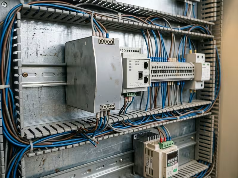
Here is the stack I expect in a well-built 24 V DIN rail supply:
- Input fuse to stop a fire if everything else fails
- MOV and EMI filter to absorb mains surges
- Input UVLO to block operation during brownouts
- OCP to handle shorts and overloads on the output
- OVP with independent sensing to catch a runaway rail
- Overtemperature protection for blocked airflow or a hot cabinet
Run a fault through that stack and something always catches it. A lightning spike hits the MOV. A shorted cable hits OCP. A failed optocoupler hits OVP. A collapsing grid hits UVLO.
When I review a datasheet, I look for that full set, each with a stated threshold and behavior. If a supply lists only “short-circuit protection,” it has one guard watching one door.
Where OVP Shows Up in Real Products
OVP looks different in every product, because the overvoltage comes from a different place each time. These four examples show where the risk starts, how the protection steps in, and what I check on each datasheet.
Laptop and USB-C Chargers
A USB-C PD charger doesn’t hold one fixed output. It negotiates 5 V, 9 V, 15 V, or 20 V with the device, and newer EPR chargers go up to 48 V. A glitch in that negotiation, or a failed feedback loop, can put 20 V on a port that should deliver 5 V.
Good chargers set their OVP trip point to follow the negotiated voltage, not just the highest one. The phone or laptop adds a second layer: an OVP load switch at its input that cuts the rail within a microsecond.
What to check: On the device side, look at the input withstand rating of the OVP switch. A part rated for 28 V covers standard PD. EPR designs need more.

DIN-Rail and PLC Power Supplies
In control cabinets, I see two common sources. The first is an internal feedback failure. The second is regenerative energy from motor drives, which can push a 24 V rail toward 27 V or 28 V during braking.
Most industrial supplies latch off at around 120% to 140% of nominal. On a 24 V unit, that often means a trip point near 30 V to 32 V.
What to check: Compare the trip point with the top of the adjustment range. If you set the output to 28 V, the OVP margin shrinks fast. In redundant setups, use a decoupling or ORing module so one failing supply can’t drive the shared bus high.
Vehicle Power Systems
Load dump is the classic automotive threat. If the battery disconnects while the alternator is charging, the 12 V system can spike to roughly 80 V to 100 V without suppression. Jump-starting with a 24 V truck battery creates a second, longer event.
Designs handle this with a TVS at the input and a surge-stopper controller that drives a series MOSFET. The controller clamps the rail or disconnects the load until the spike passes.
What to check: Ask whether the product meets the ISO 16750-2 load dump test. Also ask whether it covers the suppressed or the unsuppressed case. A supplier who can’t answer that question hasn’t tested for it.
Solar Inverters and Charge Controllers
Solar systems face overvoltage from both ends. On the PV side, cold weather raises panel voltage. A string with 140 V open-circuit voltage at 25 °C can reach about 155 V on a –10 °C morning. On the battery side, a disconnected battery can leave the controller output chasing panel voltage.
The controller shuts down when PV input exceeds its rating. It also stops charging at a set battery limit, such as 14.6 V for a 12 V LiFePO4 pack. The BMS adds its own disconnect.
What to check: Calculate the string’s cold-weather open-circuit voltage and keep it under the controller’s maximum PV input. Then confirm the battery OVP setting matches your battery chemistry.
Across all four products, the useful question stays the same: where does the extra voltage come from, and which part sees it first?
How to Evaluate OVP When Choosing a Power Supply
Two supplies can list the same OVP feature and protect your load very differently. The difference shows up in the details: the trip window, the reaction speed, and what happens after a fault. Engineers need to check more of those details, so they get most of the space here. Buyers can still catch the biggest risks with a short list.
For Engineers and Product Designers
When I review a supply for a new design, I check five things. Each one answers a simple question about how the protection behaves under a real fault.
- Trip threshold as a range, not one number. Ask for the minimum, typical, and maximum trip point. The minimum must sit above your highest normal output, including load-release overshoot. The maximum must sit below the lowest absolute max rating on that rail. If the output is adjustable, ask whether OVP tracks the setpoint or stays fixed. A fixed 30 V trip on a 24 V supply turned up to 28 V leaves almost no margin.
- Response time from fault to stop. A comparator delay alone tells you little. Ask how long the output keeps rising after the fault begins, at full load and at no load. No-load cases often overshoot the most, because light loading lets the output capacitors charge faster.
- Latch-off or auto-retry, and how it resets. Match the behavior to the likely fault. Internal faults call for latch-off. Also check the reset method. Some supplies need the input off for 10 seconds or more while the bulk capacitor drains. Others reset through a remote inhibit pin, which suits unattended equipment.
- Failure mode under a single fault. This is the check most teams skip. Ask what happens if the optocoupler shorts or the top divider resistor opens. A sound design uses a separate sensing path for OVP, so one failed part can’t blind both the regulation loop and the protection.
- Test conditions behind the numbers. Ask at which line voltage, load, and temperature the supplier measured the trip point. Voltage references drift with heat. A trip point that sits at 14.4 V on the bench can creep higher inside a hot enclosure at 70 °C.
If you can, ask for a scope capture of a forced feedback failure. One waveform tells you more than a page of specs.
For Buyers and Sourcing Teams
You don’t need a lab to screen a supplier. You need to know where to look and which questions to ask.
- Find the protection section on the datasheet. A good one lists the OVP trip value or range, the behavior after a trip, and the reset method. “Hiccup” and “latch” mean very different things for your equipment uptime.
- Check certification, then verify it. IEC 62368-1 or UL 62368-1 approval means a lab tested single-fault conditions. This standard covers most ITE power supplies and adapters. Ask for the CB report or certificate number and look it up in the issuer’s database. Fake marks on no-name adapters are common.
- Know what certification doesn’t cover. Safety approval confirms the supply won’t shock users or start a fire. It doesn’t promise that a 3.3 V chip on your board survives a fault. That part depends on the trip point.
- Treat cheap adapters with suspicion. Uncertified chargers often drop the second sensing path to save a few cents. Many also skip proper input fusing.
- Match the adapter to the device. Check voltage, polarity, and connector together. Universal adapters with selector switches cause many of the wrong-voltage failures I see.
- Keep the outside layers in place. Internal OVP doesn’t stop mains surges. Use a surge protector at the wall or an SPD in the panel, and ask whether the device has its own input protection.
What a Vague Datasheet Usually Means
Some datasheets list “Protections: OVP / OCP / SCP / OTP” and nothing else. Others say “full protection” or simply “OVP: yes.” I treat these as warning signs, not features.
Watch for these patterns:
- No trip value, or only a typical value with no range
- No word on latch-off versus auto-retry
- No reset method
- An output adjustment range that ends close to the stated trip point
- Identical protection text across every model in the catalog
In my experience, vague wording usually points to one of three things. The OVP may be a basic controller feature that senses the auxiliary winding and drifts ±10% or more. The supplier may have copied the text from a template. Or nobody has ever tested the protection under a real fault.
The fix takes one email. Ask for the trip range, the post-trip behavior, and a fault test report. A capable supplier sends real numbers within a day or two. A supplier who replies “it’s protected” has told you what you need to know.
Common Misunderstandings About OVP
Most OVP mistakes don’t come from bad engineering. They come from assumptions that sound reasonable in a sales meeting or a quick product review. Four of them show up again and again.
“My Surge Protector Already Covers It”
A surge protector sits at the wall. OVP sits inside the supply, on the output rail. They guard opposite ends of the chain.
The power strip clamps fast spikes that arrive from the mains. It can’t see what happens after the adapter converts AC to DC.
Suppose an optocoupler fails and the 12 V rail climbs to 18 V. The surge protector still sees a normal 230 V line. Your board takes the full 18 V.
The reverse holds too. Output OVP won’t stop a 4 kV spike from cracking the bridge rectifier. You need both.
“It Has a Fuse, So It’s Protected”
A fuse reacts to current, not voltage. A runaway rail that feeds a light load may draw well under the fuse rating. The fuse never opens, and the overvoltage keeps going.
Speed matters too. A typical fuse opens in milliseconds to seconds. A gate oxide fails in microseconds. And once a fuse blows, it’s done until someone replaces it.
I treat the fuse as the last step in the chain. It usually opens after a crowbar or a shorted TVS forces a high current. It ends a fault, but it doesn’t detect one.
“A Bigger Adapter Will Fry My Device”
Buyers raise this one constantly. The confusion comes from mixing up wattage and voltage.
A device draws the current it needs at its rated voltage. Swap a 19 V, 65 W laptop adapter for a 19 V, 90 W model, and the laptop pulls about the same current. The extra 25 W sits unused as headroom.
Voltage is the number that does damage. A 24 V adapter on a 12 V device can kill it, whatever the wattage.
So check voltage and polarity first. Then confirm the wattage meets or exceeds what the device needs. USB-C PD chargers stay safe for a different reason: they raise the voltage only after the device asks for it.
“With OVP, the Device Can’t Be Damaged”
OVP lowers risk. It doesn’t remove it.
Every OVP circuit needs time to react. A comparator plus a deglitch filter can take 10 to 50 µs. A fast spike can reach the thin gate oxide of a 3.3 V chip before the supply shuts down. A TVS helps, but at full pulse current it can still let the rail overshoot.
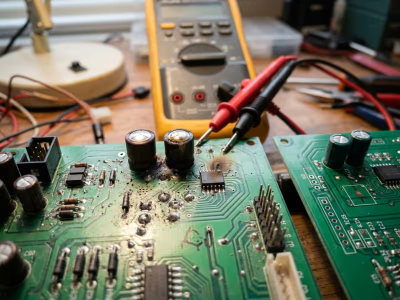
Damage also hides. A spike can weaken a capacitor or leave a small leakage path inside an IC. The device passes a quick power-on test, then fails three weeks later in the field.
After any confirmed overvoltage event, I tell clients to check more than whether the unit turns on:
- Measure standby current against a known-good unit
- Check each rail for drift and extra ripple
- Look for swollen or discolored capacitors
If the load is expensive or safety-critical, replace the stressed parts. A board that survived once isn’t a board you should trust.
FAQ
These six questions come up in almost every supplier review I join. Here are the short answers I give engineers and buyers.
What does overvoltage protection do in a power supply?
OVP watches the output rail and acts when the voltage climbs past a set limit. It shuts the output down, clamps it, or forces a fuse to open.
Its main job is to stop internal faults from pushing excess voltage into your load. A failed feedback loop and a shorted regulator are the most common examples.
What voltage level triggers OVP?
Most manufacturers set the trip point 10% to 30% above the nominal output. A 12 V supply often trips near 14 V to 15 V. A 24 V industrial unit often trips near 30 V.
The trip point has to sit above normal ripple and overshoot. It also has to stay below the absolute max rating of the parts downstream. Ask your supplier for the full trip range, not just a typical value.
Can overvoltage damage a device even if OVP is present?
Yes. OVP needs time to react. Once you include its noise filter, that delay often runs 10 to 50 µs. A fast spike can punch through a chip’s gate oxide before the supply shuts down.
OVP also can’t help when the high voltage comes from outside the supply, such as a wrong adapter. Two additions close those gaps:
- A TVS diode at the load
- Input protection on the device itself
Is OVP the same as surge protection?
No. Surge protection sits at the input. It clamps fast spikes from lightning and grid switching.
OVP sits at the output. It catches a DC rail that runs too high.
A surge protector won’t stop a broken feedback loop. Output OVP won’t stop a 4 kV mains spike. You need both.
Do all chargers and power adapters include OVP?
No. Certified adapters from reputable makers almost always include it, because safety testing covers single-fault conditions.
Cheap, uncertified chargers often skip the independent sensing path or drop OVP entirely. Check the datasheet for a stated trip value. Then verify the certification number with the issuing lab.
What is the difference between OVP and OCP?
OVP watches voltage. OCP watches current.
During a short circuit, current jumps and voltage collapses. OCP trips, and OVP stays quiet. When a feedback loop fails under a light load, voltage climbs while current stays low. OVP trips, and OCP sees nothing wrong.
A well-built supply uses both.
Check the Protection, Not Just the Output Voltage
Overvoltage doesn’t come from one place. Lightning and grid switching hit the input. Failed optocouplers, cracked sense resistors, and shorted regulators push the output up from inside the supply. Find the source first, and you’ll know which protection has to catch it.
OVP guards the output rail, and it does that job well. But it watches only one signal. A surge protector, an MOV, OCP, UVLO, and a fuse each cover a fault that OVP can’t see. The supplies I trust stack all of them, so every likely failure meets at least one guard.
Voltage and wattage tell you whether a supply fits your device. They don’t tell you how it fails. Look for a stated trip range, the post-trip behavior, and the reset method on any power supply you shortlist. If the datasheet says only “OVP: yes,” ask for numbers before you buy.