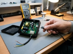
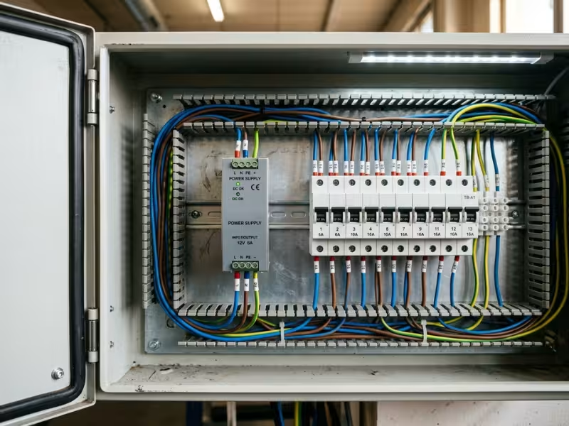
A panel builder mounts a DIN rail power supply inside a distribution board. It runs fine for months. Then lightning strikes a nearby line, and a 4 kV spike arcs across its insulation.
The supply carried an OVC II rating. Its spot in the board called for OVC III.
Overvoltage category (OVC) tells you how large a voltage spike your equipment can safely withstand.
IEC 60664-1 sets these levels, so it shapes the spacing, insulation, and ratings you specify.
I help clients sort out OVC questions every week. This guide shows how OVC II and OVC III differ and how to choose the right one.
The Fastest Way to Tell OVC II From OVC III
You rarely need the full standard to sort out an OVC question. You need one honest look at where the equipment connects. Start there, and the answer usually shows up in under a minute.
Ask One Question First
When a client sends me a spec sheet, I ask one thing first. Does this product plug in, or is it part of the installation?
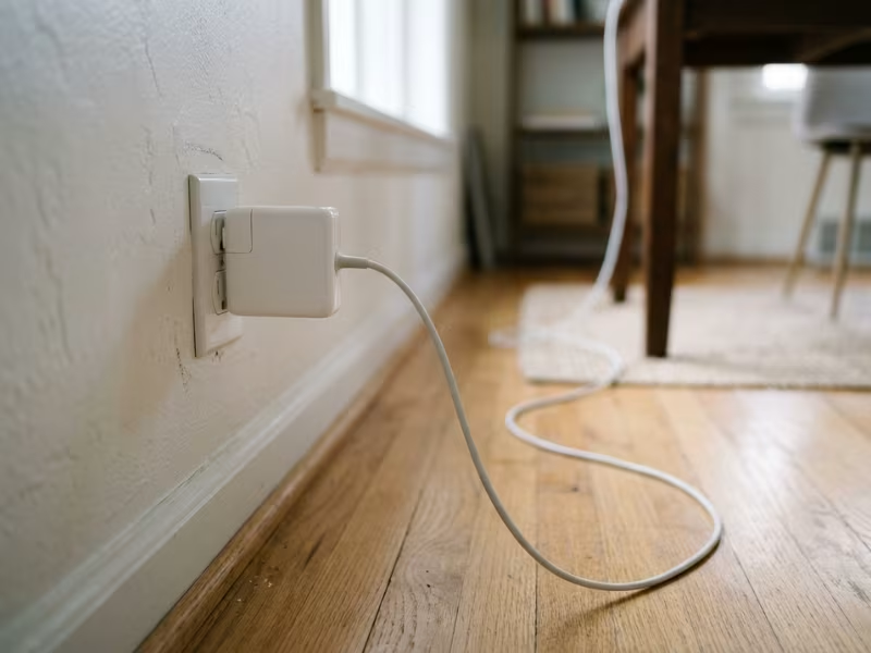
If it plugs into a wall socket, think OVC II. Laptops, monitors, kitchen appliances, and plug-in adapters live here. The building wiring and its protection sit between them and the outside world.
If an electrician wires it in permanently, think OVC III. Breakers, distribution boards, fixed motor controls, and wiring accessories belong to the installation itself. They meet a spike before any socket outlet does.
Follow the Wire, Not the Label
Marketing words won’t settle this. “Industrial-grade” describes toughness, not impulse withstand. “Surge protected” means the product has some internal suppression. Neither tells you which category the insulation meets.
So trace the cable back toward the service entrance. The closer the equipment sits to the incoming supply, the bigger the transients it must survive.
On a 230 V system, OVC II calls for 2.5 kV impulse withstand. OVC III calls for 4 kV. Look for both the category and the rated impulse voltage in plain numbers on the datasheet.
Where the Line Gets Blurry
A few products don’t fit neatly. Hardwired EV chargers, grid-tied inverters, and DIN rail power supplies start most of the debates I see.
A DIN rail supply often carries an OVC II rating, yet it mounts inside an OVC III board. That works only when an SPD or the installation design limits spikes at that point. Without that protection, you need an OVC III part or extra protection in front of it.
If the equipment is… | It usually points to… |
|---|---|
Plugged into a standard wall socket | OVC II |
A portable tool or appliance with a cord and plug | OVC II |
Hardwired into the building’s fixed wiring | OVC III |
Mounted in a distribution board or on a DIN rail inside it | OVC III, unless upstream protection is documented |
A hardwired EV wall charger | OVC III in most cases |
A grid-tied inverter’s AC connection | OVC III on the AC side; confirm with the product standard |
At the meter or service entrance | OVC IV |
When a product sits right on the boundary, treat it as the higher category until its product standard says otherwise.
What Overvoltage Category Actually Means
The quick test gets you close. But you still need to know what the rating promises, because that promise shapes your insulation, spacing, and product choice. Here is the plain version, without the textbook.
A Simple Definition
Overvoltage category tells you how large a voltage spike your equipment can survive without its insulation breaking down. These spikes last only microseconds. They come from lightning, utility switching, or large motors turning off nearby.
IEC 60664-1 sets the framework. It links each category to two things: the nominal voltage of the supply and the equipment’s position in the installation.
A product never gets an OVC rating in isolation. “OVC III” means little until you add “at 230 V” or “at 300 V to earth.”
Why the Scale Runs From I to IV
Picture the path a spike takes from the utility pole to your desk. It starts large at the service entrance. Cable impedance, breakers, and SPDs absorb part of it at each stage, so it shrinks as it moves deeper into the building.
The categories follow that path:
- OVC IV sits at the origin, where spikes arrive at full strength.
- OVC III covers the fixed wiring and distribution equipment.
- OVC II covers loads fed from socket outlets.
- OVC I covers circuits that already have dedicated protection in front of them.
A lower number means a quieter, more protected spot. A higher number means the equipment sits closer to the source and must withstand more. On a 230 V system, the rated impulse voltage climbs from 1.5 kV at OVC I to 6 kV at OVC IV.
Why This Rating Drives Real Decisions
I treat OVC as a design input, not a label for the back of the datasheet. It sets the rated impulse voltage, and that number sets the minimum clearance across your insulation.
The jump matters. For basic insulation at 230 V, OVC II needs about 1.5 mm of clearance. OVC III needs about 3.0 mm. That extra spacing changes transformer construction, PCB layout, terminal blocks, and enclosure size.
It also affects buying and approval. If you choose a component rated below its real position, it can fail certification or break down in the field. If you choose one rated well above it, you pay for size and cost you never needed.
The Four OVC Levels in Practical Terms
Each category matches a physical spot in the electrical system. Once you can picture those spots, most rating questions become simple.
OVC I: Circuits Behind Their Own Protection
OVC I covers circuits that already have something in front of them limiting spikes. Think of signal-level electronics, telecom interfaces, or the low-voltage secondary side behind an isolation transformer.
You rarely choose OVC I for mains-connected hardware. It mostly shows up inside a product, where the designer has deliberately reduced the transient level.
OVC II: Everything at the End of a Plug
This is where most end-use products live. If a cord and plug connect the equipment to a socket outlet, OVC II is usually the right starting point.
Common examples include:
- Laptops, monitors, and printers
- Kitchen and household appliances
- Plug-in power adapters and chargers
- Portable power tools
- Power strips
These products sit at the far end of the building wiring. By the time a spike reaches them, the cable run and upstream protection have already absorbed part of it. That is why a 230 V OVC II product only needs to withstand 2.5 kV.
One detail confuses many buyers. The socket outlet itself belongs to OVC III, because it is part of the fixed wiring. The appliance you plug into it belongs to OVC II.
OVC III: The Building’s Fixed Wiring
OVC III covers equipment that forms part of the installation itself. An electrician wires these products in permanently, and they stay in place for years.
Typical OVC III equipment includes:
- Distribution boards and consumer units
- Circuit breakers, RCDs, and isolators
- Wiring accessories such as sockets and switches
- Hardwired heating, lighting, and HVAC controls
- Fixed motors and permanently connected industrial machines
- DIN rail devices mounted inside a board
This equipment sits closer to the incoming supply, so it sees larger spikes. It also stays in service longer and often supports other loads downstream. At 230 V, it must withstand 4 kV.
When I review a panel design, I check every component in the board against OVC III. A single part rated lower often becomes the weak link.
OVC IV: Where the Supply Enters
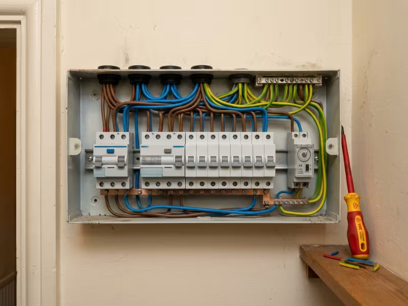
OVC IV sits at the origin of the installation. Utility meters, main breakers, and service entrance equipment live here. At 230 V, they must withstand 6 kV.
Most product designers never work at this level. Utilities and switchgear makers handle it.
OVC Level | Typical Position | Common Examples |
|---|---|---|
OVC I | Protected internal or signal-level circuits | Telecom interfaces, isolated secondary circuits |
OVC II | Plug-in loads fed from socket outlets | Appliances, IT equipment, adapters, portable tools |
OVC III | Fixed installation and distribution level | Distribution boards, breakers, sockets, hardwired controls |
OVC IV | Service entrance and origin of supply | Utility meters, main breakers, incoming service gear |
For most real decisions, the choice comes down to OVC II or OVC III. The line between them follows a simple rule: is the equipment plugged in, or is it permanently wired in?
Where OVC II Fits
Most products that engineers design and buyers source end up here. OVC II covers the huge middle ground of everyday electrical equipment, so it helps to know exactly why it works and where its limits are.
The Equipment That Lives at the End of a Cord
If you can unplug it and carry it to another room, it probably belongs in OVC II. The usual suspects include:
- Household appliances: kettles, microwaves, washing machines with a plug
- Office electronics: desktop PCs, monitors, printers, network gear
- Plug-in power supplies: laptop adapters, USB chargers, desktop medical adapters
- Portable tools: drills, saws, and corded garden equipment
- Power strips: including models with built-in surge suppression
Most product standards for this kind of gear, such as IEC 62368-1 for ICT equipment, assume OVC II conditions on the mains input by default. That assumption shapes the whole insulation design.
Why 2.5 kV Is Usually Enough
A plug-in product sits at the far end of the building’s wiring. By the time a lightning or switching spike reaches the socket, it has already traveled through the service entrance, the distribution board, and meters of branch cable. Each stage absorbs part of it. Many installations also have an SPD at the board that clips the largest surges.
So the equipment only needs to withstand what survives that trip. On a 230 V system, that means 2.5 kV for basic insulation.
That lower number saves real space. Basic insulation at OVC II needs about 1.5 mm of clearance, compared with 3.0 mm at OVC III. For reinforced insulation across the primary-to-secondary barrier, the gap grows to about 3.0 mm at OVC II versus 5.5 mm at OVC III.
On a compact 65 W adapter, that difference decides the transformer size, the slot widths on the PCB, and often the housing itself.
I push clients to stay at OVC II whenever the product truly is plug-in. Designing a phone charger to OVC III adds cost and bulk with no safety benefit.
Socket-Fed Doesn’t Mean Surge-Free
This is where many teams get the logic wrong in both directions.
First, a socket outlet doesn’t guarantee a quiet supply. Older homes often have no SPD at all. A long branch circuit shared with an air conditioner or pump can deliver sharp switching transients. OVC II assumes the installation does its part. It does not promise that spikes never arrive.
Second, those surges don’t automatically push your product into OVC III. The category follows the equipment’s position, not every possible event. If you expect a rough supply, add protection inside the product instead. A properly rated MOV, a fuse ahead of it, and a solid input filter handle most real-world spikes at a fraction of the cost of OVC III spacing.
Move up a category only when the product standard requires it, or when the equipment actually becomes part of the fixed installation.
Where OVC III Fits
OVC II covers the products people plug in. OVC III covers the hardware those products depend on: the boards, breakers, and fixed equipment that make up the installation itself. That shift in position changes how you design and choose this equipment.
The Equipment That Belongs to the Installation
My quick test is simple. If removing the product means calling an electrician, it probably belongs in OVC III. The usual candidates include:
- Distribution equipment: consumer units, sub-boards, breakers, RCDs, isolators, and DIN rail devices mounted inside them
- Hardwired building controls: lighting controllers, HVAC controls, contactors, timers, and fixed heating thermostats
- Fixed motors: pumps, fans, compressors, and machine drives wired straight into a circuit
- Industrial sockets: IEC 60309-style outlets and wall-mounted connection points
- Permanently connected EV chargers: wall boxes fed from their own dedicated circuit
These products don’t sit at the end of a cord. They form part of the path that power takes to reach everything else.
Why OVC III Has to Handle Bigger Spikes
Position explains most of it. A spike that enters at the service entrance loses part of its energy as it travels through cable, breakers, and protective devices. OVC III equipment sits early on that path, so it sees more of the original surge.
OVC III equipment also has less to protect it. A laptop gets help from meters of branch wiring and any SPD at the board. A breaker inside that same board gets far less help, because it sits right next to the incoming feed.
The role matters too. A failed toaster takes out one appliance. A failed DIN rail power supply can drop a whole control panel or a building’s lighting. Fixed equipment also stays in service for 15 to 25 years, so it will see many more transient events over its life.
That is why the standard asks for 4 kV of impulse withstand at 230 V. For three-phase 230/400 V systems, the 4 kV figure still applies, because the line-to-earth voltage sets the rating.
What Changes When You Design to OVC III
The jump from 2.5 kV to 4 kV looks small on paper. On a real board, it touches nearly every insulation decision.
- Clearance grows fast. Basic insulation at 230 V needs about 3.0 mm of clearance at OVC III, compared with about 1.5 mm at OVC II. Reinforced insulation across the primary-to-secondary barrier moves up to the 6 kV level, which calls for about 5.5 mm.
- Creepage often follows. Working voltage, pollution degree, and material group set creepage, not OVC. But creepage can never be shorter than its matching clearance. So at OVC III, the larger clearance often becomes the real limit on your PCB spacing.
- The transformer gets bigger. Wider margins, extra layers of insulating tape, or triple-insulated wire all add volume. Expect a larger core or a taller bobbin on a compact supply.
- Board and terminal choices change. You may need routed slots under the transformer, wider gaps between mains and low-voltage traces, and terminal blocks rated for the higher impulse voltage. Conformal coating won’t rescue a short clearance, because clearance measures distance through air.
- Testing gets tougher. The product must pass a higher impulse or dielectric test. Weak points that slipped through at OVC II often show up here.
Together, these changes push up the size, weight, and cost. On a DIN rail supply, I often see a wider housing or a lower power rating in the same width.
You have one alternative. If the installation includes a properly coordinated SPD at that point, IEC 60664-1 lets you treat the downstream equipment at a lower category. Document that protection clearly. Without it, the reviewer will hold you to OVC III.
When I check a panel, I look past the main components to the small parts too. A relay, a sensor supply, or a terminal block rated for OVC II can quietly become the weak point in an OVC III board.
OVC II vs OVC III: The Differences That Affect Real Products
On paper, OVC II and OVC III sit one step apart. On a real product, that step changes the spacing, the transformer, the housing, and the price. Here is where the gap shows up and what it means for your next spec sheet.
Where Each One Sits
OVC II equipment sits at the end of a cord. Branch wiring, the distribution board, and often an SPD stand between it and the incoming supply.
OVC III equipment is part of that wiring. It lives in the board, on the wall, or on a dedicated circuit. Less stands in front of it, so it sees more of each spike.
I ask clients to point at the product on a single-line diagram. If they point downstream of a socket, we talk OVC II. If they point at the board or the fixed wiring, we talk OVC III.
Impulse Withstand at Common Voltages
The category alone doesn’t set the number. You also need the line-to-earth voltage. Here are the rated impulse voltages most teams work with:
System | OVC II | OVC III |
|---|---|---|
120 V single-phase (North America) | 1.5 kV | 2.5 kV |
230 V single-phase or 230/400 V three-phase | 2.5 kV | 4 kV |
277/480 V three-phase | 2.5 kV | 4 kV |
On a 230 V system, the jump from OVC II to OVC III adds 1.5 kV. That is a 60% rise in the spike your insulation must survive.
What Changes in Insulation, Spacing, and Enclosure
Clearance follows impulse voltage directly. At 230 V and pollution degree 2, basic insulation needs about 1.5 mm at OVC II and 3.0 mm at OVC III. Reinforced insulation moves from about 3.0 mm to 5.5 mm.
That extra distance spreads through the whole design:
- Transformer: more margin tape, thicker insulation, or triple-insulated wire
- PCB: wider gaps between mains and SELV traces, and often routed slots
- Terminals: blocks rated for 4 kV impulse, with wider pitch
- Enclosure: more internal air gap around live parts
Coating and potting won’t shrink clearance, because clearance measures distance through air.

What It Does to Cost and Size
On compact products, OVC III spacing often costs 10–20% more board area around the primary side. On a 60 W DIN rail supply, that can mean a wider module or a lower power rating in the same width.
Expect higher costs for the transformer, safety parts, and testing too. For a plug-in adapter, that money buys nothing. For a board-mounted supply, it buys the right to sit there.
What Happens When You Choose Too Low
An OVC II part in an OVC III spot often works for months. Then a switching surge or nearby lightning strike arrives, and the weak points give way:
- Flashover across a tight clearance, often at the transformer or terminal block
- A tripped breaker or a dead control panel
- Carbon tracks that keep leaking current after the event
- A failed safety review when an inspector checks the ratings against the installation
The real risk stays invisible until it happens. Nothing on the bench warns you.
Item | OVC II | OVC III |
|---|---|---|
Typical location | Socket-fed loads downstream of the board | Fixed wiring, distribution boards, hardwired circuits |
Common examples | Appliances, IT gear, plug-in adapters, portable tools | Breakers, DIN rail supplies, hardwired controls, EV wall boxes |
230 V impulse level | 2.5 kV | 4 kV |
Basic clearance at 230 V (PD2) | About 1.5 mm | About 3.0 mm |
Design impact | Compact spacing, smaller transformer, lower cost | Wider clearances, heavier insulation, larger housing |
Typical buyer/specifier | Product designers, OEM sourcing teams | Panel builders, electricians, installation engineers |
Under-spec risk | Rare, if the product truly plugs in | Flashover, panel outages, failed inspections |
When a datasheet lists only “OVC II” for a part going into a board, ask for the impulse rating and the upstream SPD details before you sign off.
Common Cases That Confuse Buyers and Designers
Most OVC mistakes don’t come from the textbook cases. Nobody argues about a toaster or a main breaker. The trouble starts at the edges, where a product looks like one thing but connects like another.
Surge Protectors and SPDs Don’t Define OVC
Many buyers assume an SPD settles the question. It doesn’t.
SPD types come from IEC 61643-11, a separate standard. Each type describes the protector, not the equipment behind it:
- Type 1 sits at the service entrance and handles direct lightning current.
- Type 2 sits in distribution boards and limits switching and induced surges.
- Type 3 sits close to sensitive loads and adds a final layer.
OVC describes how much the equipment itself can withstand. An SPD in the board doesn’t move a breaker or a DIN rail device out of the fixed installation.
IEC 60664-1 does let you use a lower category behind protection. But that only works with a coordinated design. You need a known SPD protection level (Up) below the equipment’s rated impulse voltage, and you need it on paper.
A Type 2 SPD with an Up of 1.5 kV can protect 2.5 kV equipment. An unnamed “surge protector” somewhere upstream protects nothing in a safety review.
A Wall Socket Doesn’t Automatically Settle the Decision
The socket outlet belongs to OVC III. It is part of the fixed wiring, just like the cable behind it.
The appliance you plug into it usually belongs to OVC II. But not everything mounted near a socket counts as plug-in equipment.
Look at towel rail heaters, water heaters, and wall-mounted controllers fed through a fused spur or a flex outlet plate. They sit beside sockets and look like ordinary appliances. Yet an electrician wires them in, and they stay put. That makes them part of the fixed installation.
So I ask clients one practical question. Does the product leave the wall with a plug, or does it need a screwdriver?
Hardwired EV Chargers Usually Point to OVC III
EV wall boxes cause regular debate because they look like consumer products. Homeowners buy them online, and they come in sleek housings.
But look at how they connect. An electrician runs a dedicated circuit from the board, often 32 A, and wires the charger straight into it. No plug, no socket, no branch circuit shared with other loads. That is fixed-installation equipment.
Product standards such as IEC 61851-1 reflect this. Expect the mains side of a permanently connected charger to meet OVC III, and check the datasheet for a 4 kV rating at 230 V. Portable chargers with a plug are a different story. They usually fall under OVC II.

Some Power Products Span Two Roles
This is the case I see most often in panel reviews.
A DIN rail power supply often carries an OVC II rating, because its maker certified it to a general equipment standard. Then a panel builder clips it into a distribution board, which is OVC III territory.
Grid-tied inverters split differently. Their AC side connects to the fixed wiring and typically needs OVC III. Their DC PV input may carry a lower category, depending on the system design and IEC 62109-1.
When a product spans two roles, you have three clean options:
- Choose an OVC III-rated version. Many DIN rail ranges offer one, often with a slightly lower power rating per width.
- Add documented protection. Install a Type 2 or Type 3 SPD with an Up below the part’s rated impulse voltage, and record it in the panel file.
- Ask the supplier for test data. Some OVC II parts pass a 4 kV impulse test but don’t advertise it.
Never leave the gap unresolved. Inspectors check ratings against position, and so do lightning strikes.
How to Choose the Right OVC Rating
Most OVC mistakes happen because teams skip a step or take the steps in the wrong order. I use the same five-step path on every review, whether the product is a 20 W adapter or a 480 V panel supply. Each step narrows the answer, so by the end the category is a documented decision rather than a guess.
- Locate the equipment in the installation chain.
Draw a single-line diagram, even a rough one. Mark the service entrance, the distribution board, the fixed wiring, and the socket outlets. Then place your product on it.
If it sits downstream of a socket and connects with a plug, start at OVC II. If it sits in the board, on a dedicated circuit, or anywhere an electrician wires it in, start at OVC III. If it sits at the meter or main breaker, you are at OVC IV.
This step takes five minutes. It also settles most of the arguments I hear in design meetings. - Check the product standard first.
The product standard sets the minimum category, and it overrides your own judgment. IEC 60664-1 provides the framework, but the product standard tells you how to apply it.
A few common examples:
For North America, check the matching UL version, such as UL 62368-1 or UL 61010-1. These can include national deviations. - IEC 62368-1 (ICT and AV equipment) assumes OVC II on the mains input.
- IEC 60335-1 (household appliances) also works from OVC II for plug-in products.
- IEC 61010-1 (lab and measurement equipment) treats mains inputs as OVC II, but measurement circuits carry their own CAT ratings.
- IEC 60947 (low-voltage switchgear) states a rated impulse voltage (Uimp), often 4 kV or 6 kV.
- IEC 61851-1 (EV charging) and IEC 62109-1 (PV inverters) both push fixed-connected equipment toward OVC III.
- Confirm the nominal voltage and system type.
The category alone doesn’t give you a number. You also need the line-to-earth voltage, because IEC 60664-1 groups systems into voltage bands.
Watch out for IT systems and corner-grounded delta supplies. In those cases, the line-to-earth voltage can rise to the full line-to-line value during a fault. I size those designs to the line-to-line voltage. - 120 V systems (150 V band): OVC II = 1.5 kV, OVC III = 2.5 kV
- 230 V or 230/400 V (300 V band): OVC II = 2.5 kV, OVC III = 4 kV
- 277/480 V (300 V band): OVC II = 2.5 kV, OVC III = 4 kV
- 347/600 V (600 V band): OVC II = 4 kV, OVC III = 6 kV
- Verify impulse withstand and spacing.
Now turn the rated impulse voltage into physical distances. For pollution degree 2 and inhomogeneous fields, the minimum clearances are:
Reinforced insulation steps up one impulse level. So a 230 V OVC III design needs about 5.5 mm across the primary-to-secondary barrier.
Above 2,000 m, apply the altitude factor. Clearances grow by about 14% at 3,000 m and 29% at 4,000 m. Then confirm creepage. It must meet its own table based on working voltage and material group, and it can never be shorter than the matching clearance.
On a supplier’s part, don’t accept “OVC III” as a bare claim. Ask for the impulse test voltage and the clearance figures. - 2.5 kV → about 1.5 mm
- 4 kV → about 3.0 mm
- 6 kV → about 5.5 mm
- If the role is mixed, design to the higher category.
Some products sit on two sides of the line. A DIN rail supply that ships to both machine builders and panel builders is a good example, and so is an inverter with an AC side and a DC side.
In these cases, I design to OVC III unless a coordinated SPD is documented at the installation point. That protection must have an Up below the product’s rated impulse voltage. Designing to the higher category costs some board area. Redesigning after a failed inspection or a field flashover costs far more.
Write each answer down as you go: the position, the standard, the voltage band, the impulse rating, and the clearances. That one page becomes your evidence when a reviewer, an inspector, or a customer asks why you chose that category.

Real-World Examples
Rules make more sense once you see them on real hardware. These four products come up in my reviews again and again, and each one shows where the OVC II and OVC III line falls in practice.
Laptop Charger
A laptop charger plugs into a wall socket in a home or office, at the far end of the building’s branch wiring.
That position points to OVC II. A 230 V model needs 2.5 kV impulse withstand on its mains input, and IEC 62368-1 assumes exactly that.
The judgment point sits inside the charger. The primary-to-secondary barrier uses reinforced insulation, which steps up to the 4 kV level. The low-voltage output behind it faces only small transients.
Residential Distribution Board
A distribution board mounts on the wall where the incoming supply splits into the home’s circuits. It holds breakers, RCDs, and often a DIN rail device or two.
Everything inside belongs to the fixed installation. So each component needs OVC III and 4 kV withstand at 230 V.
The judgment point is the small parts. A DIN rail power supply or timer rated only for OVC II needs an OVC III version or a documented SPD with an Up below its rating.
Hardwired EV Charger
An electrician wires an EV wall box into its own dedicated circuit from the board, often rated at 32 A, with no plug in between.
That permanent connection makes it part of the fixed installation. IEC 61851-1 pushes its mains side toward OVC III, with a 4 kV rating at 230 V.
The judgment point is the connection method. A portable charger that plugs into a socket usually falls under OVC II. The same electronics in a hardwired box do not.
Solar Inverter AC-Side Connection
A grid-tied inverter feeds its AC output into the home’s board through a dedicated breaker. It often hangs in a garage or utility room.
That AC side connects straight to the fixed wiring, so it typically needs OVC III under IEC 62109-1.
The judgment point is the split inside one product. The DC PV input may carry a different category, depending on string design, cable runs, and any DC surge protection.
Look across all four and one pattern stands out. The product’s size, price, and look never decide the category. The way it connects to the building does, so check the connection before you check the datasheet.
FAQ
These six questions come up in nearly every design review and panel check I join. Here are the short answers I give engineers, panel builders, and product designers.
What does overvoltage category mean in simple terms?
Overvoltage category tells you how large a voltage spike your equipment can survive without its insulation breaking down. IEC 60664-1 ties each category to two things: the supply voltage and the equipment’s position in the installation.
The closer the equipment sits to the incoming supply, the higher the category it needs. On a 230 V system, the rated impulse voltage climbs from 1.5 kV at OVC I to 6 kV at OVC IV.
Is OVC II enough for household appliances?
Yes, for plug-in appliances. A kettle, TV, or laptop adapter sits at the end of the branch wiring, where cable runs and upstream protection have already absorbed part of each spike. IEC 60335-1 and IEC 62368-1 both work from OVC II on the mains input.
Hardwired appliances differ. A water heater on a fused spur belongs to the fixed installation, so check it against OVC III.
What is the difference between OVC II and OVC III?
Position drives the difference. OVC II covers socket-fed loads. OVC III covers the fixed wiring and everything wired into it, such as breakers, distribution boards, and DIN rail devices.
At 230 V, OVC II requires 2.5 kV impulse withstand and OVC III requires 4 kV. That jump roughly doubles basic insulation clearance, from about 1.5 mm to 3.0 mm.
Does an SPD replace the need for a higher OVC?
Only with a coordinated, documented design. IEC 60664-1 lets you use a lower category behind protection. But the SPD’s voltage protection level (Up) must sit below the equipment’s rated impulse voltage, and you need that on paper.
A Type 2 SPD with an Up of 1.5 kV can protect 2.5 kV equipment. An unnamed “surge protector” somewhere upstream won’t satisfy a safety reviewer.
Which overvoltage category applies to EV chargers?
It depends on the connection. An electrician wires a hardwired wall box into its own dedicated circuit, so it becomes part of the fixed installation. Expect OVC III on the mains side, with 4 kV withstand at 230 V, in line with IEC 61851-1.
A portable charger that plugs into a socket usually falls under OVC II.
Does altitude affect OVC-related insulation requirements?
Yes. The category stays the same, but the clearances grow. IEC 60664-1 clearance tables assume operation up to 2,000 m. Above that, thinner air breaks down at lower voltages, so you multiply clearances by a correction factor:
- 3,000 m: about 1.14
- 4,000 m: about 1.29
- 5,000 m: about 1.48
Altitude doesn’t change creepage requirements. If your product ships to mining sites or high-altitude cities, state the maximum operating altitude on the datasheet and size the clearances to match.
Match the Category to the Installation Position
Most OVC mistakes don’t start in the lab. They start at the spec sheet, when someone trusts a label like “industrial-grade” or “surge protected” instead of looking at where the product connects.
Position decides the category. A plug-in load usually sits at OVC II. Anything an electrician wires into the building, such as breakers, DIN rail supplies, and hardwired chargers, sits at OVC III.
Next, let the product standard set your floor. IEC 62368-1, IEC 60335-1, IEC 61851-1, and their UL versions tell you the minimum before your own judgment comes in.
When a product sits on the boundary or plays two roles, design to the higher category. Fixed-installation equipment should default to OVC III unless you can document a coordinated SPD in front of it.
Before you approve your next part, mark it on a single-line diagram. Then confirm its rated impulse voltage and clearance figures in writing.