Most medical power supplies don’t fail certification at the final test. They fail because of choices the team made months earlier.
I review power designs for patient-connected devices often, and I keep seeing the same pattern. A team picks the wrong insulation scheme or leaves leakage current for the lab to find. Then the rework starts.
This guide skips the clause-by-clause tour of IEC 60601-1. It focuses on the seven design decisions that shape the certification path for medical power supplies. If you lead engineering or product work on a clinical device, these are the choices to settle first.
A quick note: the figures and examples here are practical reference points, not substitutes for the standard. Your exact requirements depend on device classification, applied part type, operating conditions, and your final test plan. Always confirm them with your test lab.
Why Medical Power Supplies Fail Late for Early Reasons
A power supply that runs perfectly on your bench can still fail certification. The cause usually traces back to a decision made long before anyone booked lab time.
The Risk Boundary Moves Closer to the Patient
Industrial and IT supplies protect a trained operator or a healthy user. Medical supplies protect someone who may be unconscious, wired to sensors, or connected through a catheter. That shift tightens almost every rule:
- Leakage current. For CF applied parts, patient leakage limits drop to 10 µA in normal condition. Many commercial supplies leak far more.
- Isolation paths. Since its third edition, IEC 60601-1 splits protection into MOOP for operators and MOPP for patients. MOPP calls for wider spacing and higher test voltages.
- EMC immunity. A noisy supply can upset a monitor or an infusion pump. Reviewers treat that as a safety issue.
“It Works” Doesn’t Mean “It Passes”
I often see boards with tight creepage under the transformer, Y-capacitors sized for EMI rather than leakage, or a ground path that only works with one module connected. None of these flaws affect function. All of them affect certification. The lab doesn’t test whether your device works. It tests whether your device stays safe when something goes wrong.
Late Fixes Cost Far More
Changing an insulation scheme on paper takes an afternoon. Changing it after layout freeze often means a board spin, a requalified transformer, new EMC tests, and updated documents. That can add weeks or months. The earlier you lock a decision, the cheaper it is to get right.
Decision 1: Define the Device Boundary Before You Pick the Power Supply
Many teams start by asking which supply to buy. That question comes too early. You can’t choose a supply until you know what it has to protect, so I ask every client three questions before we open a datasheet.
Class I or Class II: Who Carries the Protection?
A Class I device relies on protective earth plus basic insulation. If insulation fails, the earth wire carries fault current away. EMC filtering also gets easier, because Y-capacitors have a solid earth return.
A Class II device has no protective earth. Double or reinforced insulation does all the work. You skip earth continuity testing and the three-prong cord, but EMC gets harder. Any Y-capacitor current now shows up as touch current on the enclosure.
As a rule of thumb, choose Class II for portable or home-use devices where nobody can guarantee a grounded outlet. Choose Class I when you need heavy EMI filtering or have a large metal chassis.
External or Internal Power: Where Does Mains Live?
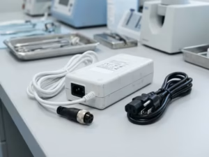
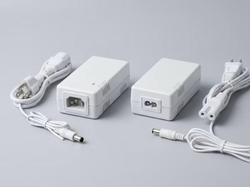
An external adapter keeps mains outside your enclosure, so internal creepage and clearance get much easier. The adapter still counts as part of your medical device, though. It needs the right medical rating, and its leakage adds to your total.
An internal supply gives you control over layout, cooling, and size. It also moves every mains spacing rule inside your product.
Battery power adds a third path. If the device can connect to a patient while charging, the mains path still matters.
Applied Parts: How Close Does Power Get to the Patient?
This question usually shapes the design most:
- No applied part: You mainly protect the operator, and MOOP rules usually apply.
- Type B: The device touches the patient, but the patient circuit doesn’t need to float from earth.
- Type BF: The patient connection floats, so you need a real isolation barrier.
- Type CF: The connection can reach the heart. Patient leakage limits drop to 10 µA, and isolation demands climb sharply.
Each answer sets your insulation path, grounding, EMC filter, and leakage budget. Change one after layout, and they all change together. These choices belong in the product requirements, not in a note to “confirm with the lab.”
One Monitor, Three Power Designs
Picture a bedside monitor planned in three versions. Version A uses an SpO2 clip and a BP cuff, both BF. A 2 MOPP medical adapter and an isolated patient front end usually cover it.
Version B adds ECG leads, which are typically CF and defibrillation-proof. The front end now needs a low-capacitance isolated DC/DC converter and defib protection. Your leakage margin shrinks from 100 µA to 10 µA.
Version C adds invasive blood pressure, which brings more CF channels and tighter leakage sharing.
The enclosure and software barely change. The power design changes a lot. My advice: design for your highest-risk configuration first, then scale down. Scaling down is cheap. Scaling up rarely works.
Decision 2: Choose Off-the-Shelf or Custom Based on Certification Risk, Not Just Cost
Most teams answer this with a spreadsheet of unit prices. I ask a different question first: which path gives your project the lowest chance of a failed submission? A custom supply might save $8 per unit, but that saving vanishes if it adds a second lab cycle.
Compare More Than the BOM Line
Factor | Off-the-shelf | Custom | When it tips the decision |
|---|---|---|---|
Submission scope | Smaller; the supply arrives with its own 60601-1 report | Larger; the lab evaluates the full supply design | You have a fixed launch date or tight test budget |
Regulatory capability | Little in-house expertise needed | Requires staff who can defend creepage, transformer, and fault data | You have no dedicated compliance engineer |
Production volume | Higher unit cost, no development cost | Lower unit cost, high upfront cost | Annual volume reaches the tens of thousands |
Size and thermal fit | Fixed footprint and cooling needs | Shaped to your enclosure and airflow | The supply won’t fit or overheats in a sealed case |
Output and transients | Standard rails, typical load response | Tuned rails, sequencing, pulse loads | Motors, lasers, or RF stages draw sharp peaks |
Redundancy | Limited options | Built-in redundancy or battery handover | Essential performance depends on uninterrupted power |
No single row decides it. Find the two or three that matter most to your product.
When a Certified Module Makes Sense
I usually steer clients toward off-the-shelf when the deadline is tight, volume is low, regulatory staff is thin, or the loads are ordinary 12 V or 24 V rails. Many teams start by reviewing existing power supply products to see whether a standard platform meets the target. A proven module also gives your first prototype a known baseline for troubleshooting.
When Custom Design Earns Its Cost
Custom makes sense when a catalog part forces you to compromise the product. That typically happens with very tight space, unusual outputs, large volumes, or power behavior that affects essential performance. In those cases, custom power adapters or a tailored medical design often fit better. Budget honestly for transformer qualification, a fuller components list, and pre-compliance testing.
A Certificate Shortens the Path but Doesn’t Finish It
A module with an IEC 60601-1 certificate and CB report reduces your submission scope. It doesn’t certify your device. Leakage still adds across your system, EMC still changes with cabling and enclosure, and the report may not cover your MOPP level, altitude, or ambient temperature.
Request the full CB report before you commit. Read the conditions of acceptability closely, because they list what your system still has to prove.
Decision 3: Lock the Insulation Strategy Early with MOOP, MOPP, and Applied Part Type
Most engineers can define MOOP and MOPP in one sentence. Far fewer can say what those terms will do to their transformer, PCB, and test plan.
MOOP and MOPP in Plain Terms
MOOP (Means of Operator Protection) guards the person using the device. Its rules sit close to IT equipment rules. MOPP (Means of Patient Protection) guards a patient who may be sedated or wired to electrodes and can’t react to a shock. MOPP calls for wider spacing and higher test voltages.
Each “means” is one layer of protection. The standard asks for two means between mains and accessible parts, so one failure never leaves someone exposed.
Why the Definitions Aren’t the Hard Part
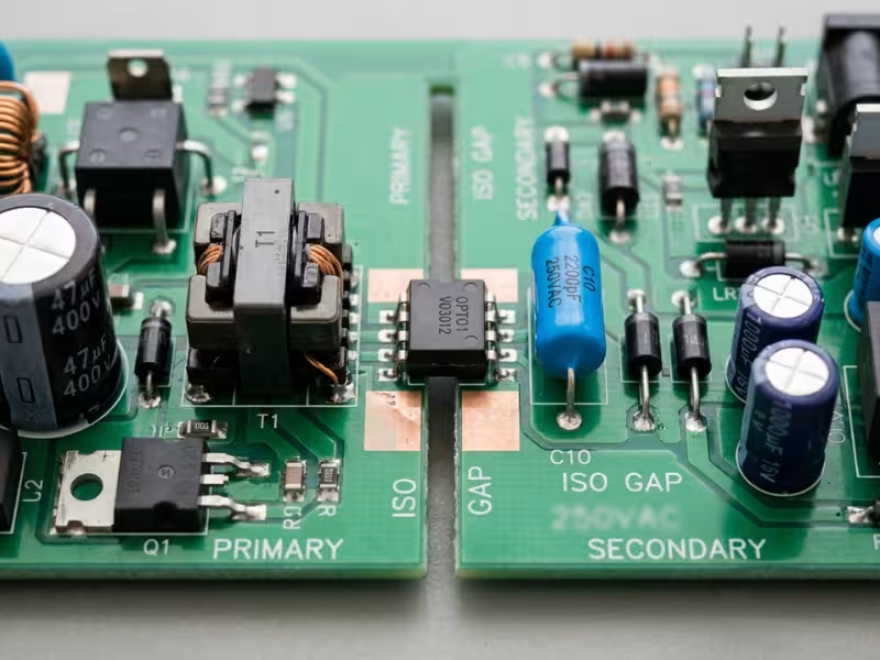
Your insulation level sets board creepage, transformer construction, optocoupler package, Y-capacitor class, and hipot voltage. Change the level after layout, and every item changes with it.
I’ve watched a team discover a 2 MOPP requirement three weeks before the lab date. The fix took a new transformer, a larger board, a new enclosure cutout, and a second EMC run. The circuit was fine. The insulation target wasn’t.
When to Use 2 MOPP and When a Mixed Scheme Works
As a practical default, plan for 2 MOPP on any path from mains to a part that can touch the patient. A mixed scheme can work when barriers clearly split the job:
- A 2 MOOP external adapter feeds a board with an isolated patient front end that provides the required MOPP.
- A 1 MOPP + 1 MOOP stack covers an operator-only port, such as a service connector, that never reaches the patient.
In most designs, reviewers won’t credit a MOOP barrier as patient protection. If your risk analysis can’t show that layer stays out of the patient path, expect a request for 2 MOPP.
What Applied Part Type Adds
Type B parts may connect to earth. Type BF parts float and need a true isolation barrier. Type CF parts bring the strictest leakage limits, very low coupling capacitance, and often defibrillation protection. Each step up tightens leakage and isolation at the same time.
What Creepage, Clearance, and Hipot Actually Cost You
At a 250 V working voltage, typical reference values look like this:
Protection choice | Typical creepage / clearance | Hipot test | Design consequence |
|---|---|---|---|
2 MOOP | ~5 mm / ~4 mm | 3,000 Vac | Many IT-style parts fit; standard optos and transformers often work |
1 MOPP | ~4 mm / ~2.5 mm | 1,500 Vac | Usually one barrier in a larger scheme; confirm the other covers the gap |
2 MOPP | ~8 mm / ~5 mm | 4,000 Vac | Larger or triple-insulated transformer, wide-body optos, Y1 caps, PCB slots, bigger footprint |
2 MOPP + CF, defib-proof | 2 MOPP spacing plus defib protection | 4,000 Vac plus defib pulse tests | Low-capacitance isolated DC/DC, surge protection, tight layout on every patient channel |
These values also depend on PCB material group, pollution degree, and altitude. Above 2,000 m, clearance grows. The 4,000 Vac hipot hits the transformer hardest, and many compact designs that pass at 3,000 Vac break down at 4,000 Vac. Qualify your transformer for the final level from the first sample.
Write It Down Before Schematic Capture
Draw a one-page insulation diagram. Show every barrier, its MOOP or MOPP rating, its working voltage, and the parts that form it. Share it with layout, mechanical, and your lab. That page costs a day. Skipping it can cost a board spin and a full retest.
Decision 4: Treat Leakage Current as a Budget, Not a Test Result
Most teams first see a real leakage number on a lab report. By then, the number is a verdict. I ask teams to treat leakage as a budget from day one, just like watts or temperature rise.
Why Leakage Needs a Budget
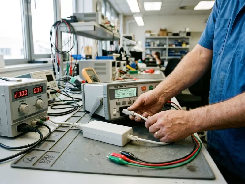
Every part that couples mains to earth, enclosure, or patient takes a share of one fixed limit. In normal condition, touch current and BF patient leakage must stay under 100 µA. CF patient leakage must stay under 10 µA.
The lab tests at 110% of your highest rated voltage and your highest rated frequency. Rate the device for 240 V at 60 Hz, and the lab measures at 264 V and 60 Hz. A bench reading at 120 V tells you very little.
Where the Budget Goes
Leakage source | Why it matters | What to check early |
|---|---|---|
Y-capacitors | One 4.7 nF Y-cap from line to earth passes about 470 µA at 264 V, 60 Hz | Total Y capacitance across every board; whether smaller values or DC-side filtering can work |
EMI filters | Filter modules often hide line-to-earth capacitors | Leakage at your test voltage and frequency, not the “typical” 115 V figure |
Mains transformer | Interwinding capacitance couples into secondary and patient circuits | Primary-to-secondary capacitance and shield connection |
Patient isolation DC/DC | Barrier capacitance sets BF and CF patient leakage | Isolation capacitance per channel |
Downstream modules | Displays, PCs, printers, and chargers bring their own Y-caps | Each module’s leakage at your test conditions |
How Passing Parts Build a Failing System
Capacitive leakage from the same mains line sums almost directly. On one cart system I reviewed, the medical supply leaked 75 µA, the display 60 µA, and the embedded PC 80 µA. Each looked fine alone. Together they reached 215 µA, more than double a Class II touch limit.
Single fault testing makes it worse. When the lab opens the earth wire on a Class I device, the whole sum appears on the enclosure and must stay under 500 µA.
When the Installation Multiplies the Problem
- Shared outlets: Several devices on one power strip share one ground conductor. IEC 60601-1 treats this as an ME system, which often calls for a separating transformer.
- Hidden ground paths: Cable shields and chassis bonds create paths you never drew.
- Added equipment: A laptop or USB charger near the patient changes your total, so your IFU should define what users can connect.
- Operating rooms: Many US line isolation monitors alarm at about 5 mA of total hazard current, and every device adds to it.
Build a Practical Budget Table
I use a spreadsheet with these columns: block, leakage type, allocated µA for normal and single fault, datasheet value, measured value per build, remaining margin, and owner. I hold back 20–30% as reserve, because capacitors drift and someone always adds a module late.
Watch for the usual mistakes: measuring at 120 V, adding Y-caps late to fix EMC, ignoring ±20% capacitor tolerance, and skipping the open-earth case.
Decision 5: Design for EMC Before Layout Is Frozen
Leakage and EMC pull on the same filter parts, so your leakage budget feeds straight into this decision. Teams that wait for the formal EMC test usually find the cheapest fixes already gone.
Why EMC Can’t Wait for the Lab
EMC failures usually trace back to layout, cable routing, or grounding, not a single part. Before layout, a filter change takes hours. After first boards, ferrites and shields help but eat into your leakage budget. After a formal failure, you often face a board spin and 6 to 12 weeks of delay.
How the Power Supply Gets Pulled In
Emissions fall under CISPR 11. Most medical devices are Group 1, and home-use devices usually need the tighter Class B limits. Your switching stage drives most conducted noise from 150 kHz to 30 MHz.
Immunity pushes energy back in. ESD, fast transients, surges, dips, and conducted RF all enter through the mains input first. The lab also checks whether the device keeps its essential performance. A monitor that raises a false alarm during a transient fails.
Why Patient Proximity Raises the Stakes
Patient cables act like antennas feeding high-gain front ends. IEC 60601-1-2 now tests proximity fields from wireless devices at levels up to 28 V/m, far above the 3 V/m baseline for professional healthcare settings. A noisy patient-side DC/DC converter can also cause baseline drift, so give it the same attention as the mains supply.
Four Moves Before Layout Freezes
- Set the input filter architecture. Choose stages, choke size, and X and Y values against your leakage budget. If Y-caps are tight, use a larger choke.
- Plan return current paths. Keep switching loops small, with solid returns directly beneath them.
- Define shielding and grounding. Decide where shields terminate and where chassis bonds to earth, all in one diagram.
- Check module EMC data. A supply that passes Class B only with an external filter isn’t a Class B supply in your system.
When Pre-Compliance Pays Off
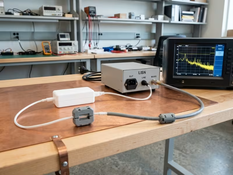
Run conducted emissions plus quick ESD and EFT checks on your first powered prototype. Run radiated and critical immunity tests again with the near-final enclosure, real patient cables, and real power cord. A pre-compliance day often costs less than one board revision.
Decision 6: Screen for Single-Fault and Abnormal Conditions Before Formal Testing
Knowing the names of the single-fault tests rarely saves a project. The useful question is which faults your design will fail and which parts a reviewer will question.
Run Your Own Fault Walk
The lab will short and open components, block vents, and overload outputs. You can predict most results from the schematic. For each part in the power path, ask:
- If it shorts or opens, what carries the fault current?
- Does a certified protective device clear it, or does something just get hot?
- Does any barrier lose a layer of protection?
Thermal design fails these tests more often than electrical design. Measure hot spots at maximum ambient and full load, then repeat with each cooling path blocked. If the transformer nears its insulation class limit, add a thermal cutoff now.
Parts That Draw Extra Scrutiny
Reviewers slow down at uncertified transformers in a MOPP barrier, uncertified optocouplers, Y-capacitors without IEC 60384-14 approval, uncertified fuses and inlets, and plastics without flammability data. For each critical part, expect requests for the part number, ratings, certificate or CB report number, temperature and flammability ratings, PCB material group, and transformer construction drawings.
Build the Critical Components List Early
The lab ties its report to the exact parts it tested, so later supplier changes can trigger re-evaluation. Start the list during component selection, request certificates with samples, and add second sources from day one. Assign one owner to update it at every BOM revision.
Decision 7: Build the Submission File While the Design Is Still Moving
Reviewers read your documents before they power up your device. In my experience, a gap in those documents can stall a review faster than a failed test.
Grow the File Alongside the Hardware
IEC 60601-1 leans on your ISO 14971 risk file to decide which tests apply and what counts as safe behavior. If that file lags, the reviewer has to guess.
Document/Item | When to start | Owner | Risk if missing late |
|---|---|---|---|
Risk management file (ISO 14971) | Concept phase | Systems or quality lead | Lab can’t scope tests; review stalls |
Essential performance definition | Before schematic capture | Systems engineer | EMC and fault tests lack pass/fail criteria |
Insulation diagram | Before schematic capture | Power design lead | Reviewer questions every barrier |
Critical components list and certificates | Component selection | Hardware and procurement | Days lost chasing suppliers or extra tests |
Labeling and IFU drafts | First prototype | Product manager | Late rating changes force relabeling |
Pre-compliance EMC and leakage data | First powered prototype | Test engineer | Formal test becomes your first measurement |
CB reports for purchased modules | Supplier selection | Procurement | Lab re-evaluates the module |
Plan for Every Market on Day One
A CB report under the IECEE CB Scheme lets one campaign support many countries, if it covers the national differences you need. The US uses ANSI/AAMI ES60601-1, Canada uses CAN/CSA-C22.2 No. 60601-1, and Europe uses EN 60601-1. Give the lab your full market list up front, and pick a body that can issue both the CB report and marks like US NRTL listing. Ask about queue times, since busy labs often book 6 to 10 weeks out.
A Realistic Timeline
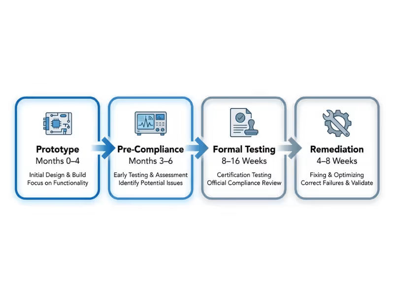
- Prototype (months 0–4): Lock classification and insulation; start the risk file and components list.
- Pre-compliance (months 3–6): Run EMC scans, leakage checks at 110% voltage, and fault walks.
- Formal testing (typically 8–16 weeks): A clean file pushes you toward the short end.
- Remediation (plan 4–8 weeks): Reserve it even if you expect to pass.
Well-prepared projects often certify within 6 to 9 months of first prototype. Projects that start the file late often take 12 months or more.
Four Mistakes That Quietly Delay Certification
Each of these looks reasonable at the time, which is why teams keep making them.
“Our IT Supply Passed IEC 62368-1, So It’s Close”
It usually isn’t. IEC 62368-1 allows touch current up to 0.5 mA for ordinary users, while a CF applied part allows 10 µA of patient leakage. A reinforced IT barrier often lands near 2 MOOP and rarely meets 2 MOPP spacing and hipot. An IT supply can sit behind a properly rated medical barrier, but on its own it won’t get you halfway there.
“We’ll Tune Leakage at the Lab”
The quick fix, removing Y-caps, usually breaks conducted emissions. The other fixes mean a new transformer or a board spin. Track leakage at 110% of rated voltage from the first prototype.
“We Bought a Certified Supply, So We’re Covered”
A certified supply covers the supply, not your system. Your other modules add leakage, your cables change EMC, and your conditions may fall outside the CB report.
“We’ll Write the Documents After Design Freeze”
Reviewers read your file before they test anything. Each round of questions can cost one to two weeks. When hardware freezes, the file should need a final review, not a first draft.
A Practical Pre-Submission Checklist
I use this list as a go/no-go gate before booking lab time. Put an owner’s name next to every item.
- Protection class is locked. Class I or II matches the cord, label, and insulation diagram.
- Applied part types are locked. Every patient connection carries a B, BF, or CF rating, with defib-proof parts marked.
- Insulation strategy is documented. One diagram shows each barrier, rating, working voltage, and parts.
- Leakage budget is allocated in writing. Each module has an owner and measured values at 110% voltage, with at least 20% in reserve.
- Pre-compliance EMC is complete. You tested a representative build with real cables, and the BOM reflects every fix.
- Critical components list is complete. Every safety part shows ratings and certificate numbers, plus second sources.
- Risk file tracks the current design. Essential performance defines clear pass criteria.
- Market list is final. The lab knows every target country before testing begins.
If you can’t tick all eight, close the gap now. A week here costs far less than a second lab slot.
FAQs
What is the difference between MOOP and MOPP?
MOOP protects an alert, trained operator who can pull away from a shock. MOPP protects a patient who may not be able to react, so it requires wider spacing and higher test voltages. Ask whether a path can ever reach the patient. If it can, plan for MOPP.
Can I use a commercial power supply in a medical device?
Yes, in specific setups. You can place it behind a barrier that already provides the required MOPP, or keep it outside the patient environment (about 1.5 m around the patient) as part of an ME system, usually with a separating transformer. Its leakage still counts toward your system total.
How long does medical power supply certification usually take?
Formal testing typically runs 8 to 16 weeks once your file is complete. The full path from first prototype usually takes 6 to 12 months. Certified modules, complete documents, and early pre-compliance push you toward the short end.
What leakage current limits matter for patient-connected devices?
IEC 60601-1 sets these key limits for normal condition (NC) and single fault condition (SFC):
Current | Type B / BF (NC / SFC) | Type CF (NC / SFC) |
|---|---|---|
Patient leakage | 100 / 500 µA | 10 / 50 µA |
Total patient leakage | 500 / 1,000 µA | 50 / 100 µA |
Touch current | 100 / 500 µA | 100 / 500 µA |
Earth leakage allows 5 mA in normal condition. Also check mains-on-applied-part testing, which drives BF and CF isolation design.
What is a CB report and why does it matter?
A CB report is a test report issued under the IECEE CB Scheme that other member bodies accept. It lets your lab reuse evidence for purchased modules and cuts duplicate testing across markets. It isn’t a market mark, so you still need national approvals like US NRTL listing.
How is IEC 62368-1 different from IEC 60601-1?
IEC 62368-1 is hazard-based and assumes users can sense and react to a problem. IEC 60601-1 is risk-based, ties to your ISO 14971 file, and adds applied parts, essential performance, and patient protection. In practice, 62368-1 helps on the operator side but won’t answer patient-side questions.
Conclusion
Most medical power supplies don’t miss certification because of one bad test result. They miss it because a few key questions stayed open too long. The hardware usually works fine. The real problem is a grounding, isolation, or patient-contact decision that nobody locked while changes were still cheap.
If you take one action from this guide, make it this one. Before anyone starts schematic capture or picks a power supply, write down three things on one page:
- Your device boundary: Class I or II, internal or external power
- Your insulation strategy: every barrier rated MOOP or MOPP
- Your applied part types: B, BF, or CF
Get your team to sign off on that page. Every other choice follows from it, and your path to certification gets much shorter.