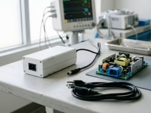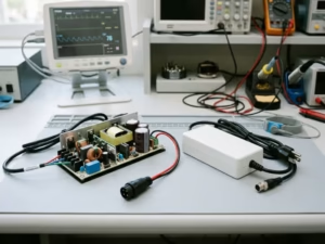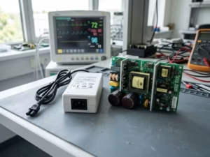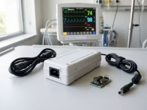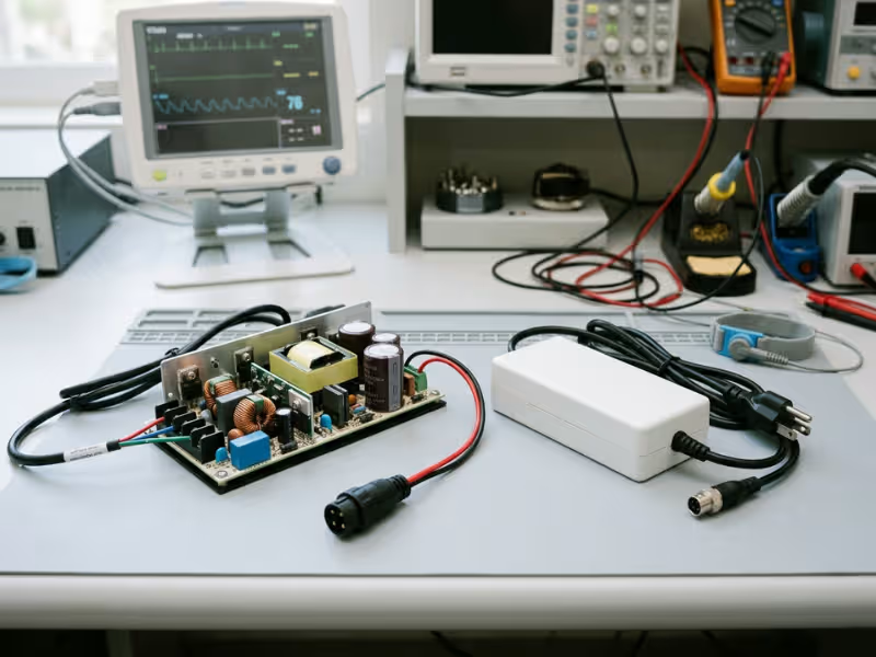
Many medical devices plug into wall power while patients connect to the device itself. That makes power isolation a real safety boundary, not just a design detail.
An isolated medical power supply converts input power into a regulated output. It uses a galvanic barrier to keep hazardous voltage away from the patient side.
That sounds simple, but medical isolation asks for more than a normal isolated supply. This guide covers what makes an isolated medical power supply different, which standards shape the decision, what to check in a datasheet, and how to choose the right unit. You can also compare real medical power supplies as you work through the criteria.
Miss the isolation details early, and the cost usually shows up later in leakage tests, EMC trouble, or a full redesign.
What an Isolated Medical Power Supply Actually Does
Strip away the jargon, and this supply does two jobs at once. It powers the device, and it keeps mains voltage away from the people around it.
Start with the definition, then look at why isolation alone doesn’t make a supply medical-grade.
The Basic Definition
An isolated medical power supply takes AC from the wall, or DC from a battery or upstream rail. It delivers a regulated DC output, such as 12 V or 24 V, that stays steady as the load changes.
Inside, a transformer moves energy through a magnetic field instead of through copper. No direct conductive path links input to output. Engineers call this galvanic isolation.
That barrier does real work:
- It blocks hazardous mains voltage from reaching the output.
- It limits how much current can leak to a patient or operator.
- It breaks ground loops that push noise into sensitive circuits.
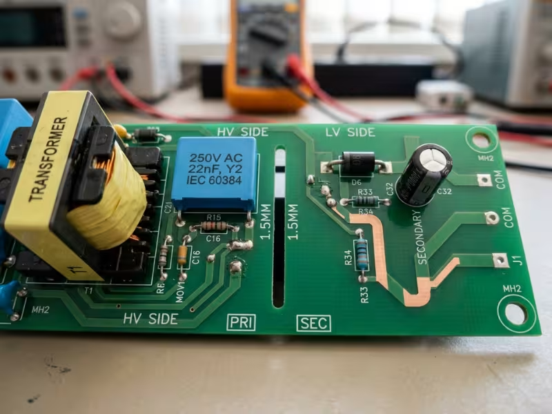
Why “Isolated” Alone Is Not Enough
Plenty of commercial and industrial supplies are isolated too. That doesn’t make them medical-grade.
A typical IT supply may pass a 3,000 VAC isolation test and allow touch current up to 3.5 mA. A 2x MOPP medical supply typically passes 4,000 VAC and keeps touch current at 100 µA or less in normal use.
Patients change the math. They may be unconscious, wired to electrodes, or unable to pull away from a shock. That’s why IEC 60601-1 demands wider spacing, stronger insulation, and far lower leakage.
How It Differs From a Standard Isolated Power Supply
On a bench, a standard isolated supply and a medical one can look almost identical. The real differences sit in the spacing, the parts list, and the paperwork.
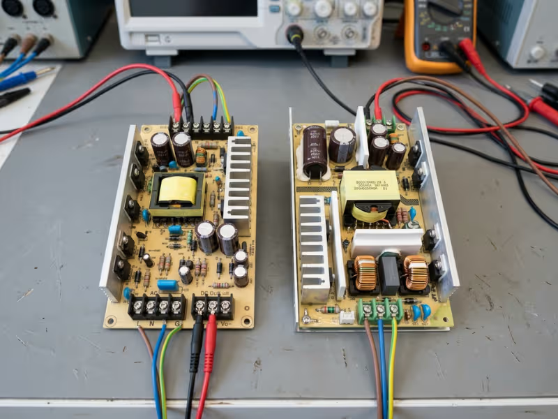
A Stronger Barrier and a Much Smaller Leak
A supply built to IEC 62368-1 often tests its reinforced insulation near 3,000 VAC, with roughly 5–6 mm of creepage. A 2x MOPP medical supply typically raises that to 4,000 VAC and about 8 mm.
Leakage tightens even more. IEC 60601-1 holds touch current to 100 µA in normal use, and Type CF patient leakage drops to 10 µA. To get there, designers cut Y-capacitance and use low-capacitance transformers. Both choices make EMC harder.
Different Standards Ask Different Questions
IEC 62368-1 and IEC 61010-1 protect a user who can feel a shock and step away. IEC 60601-1 assumes the patient may be sedated, wet, or wired to electrodes. It also covers essential performance, ISO 14971 risk management, and single-fault behavior. An auditor won’t just confirm the supply works. They’ll ask what happens when one part fails.
Extra Margin Costs Space, Money, and Time
Wider spacing eats board area, so medical units often run larger at the same power rating. Medical-rated parts, extra testing, and ISO 13485 documentation also raise the price. Plan the footprint for this from day one.
A Working Prototype Is Not a Passed Test
A commercial supply is fine for early firmware work. Trouble starts when the stand-in quietly becomes the plan. It may run perfectly and still fail leakage, hipot, or spacing checks, often after the board and enclosure are frozen.
Factor | Standard Isolated Supply | Isolated Medical Power Supply |
|---|---|---|
Main safety standard | IEC 62368-1 or IEC 61010-1 | IEC 60601-1 |
Isolation test (input to output) | Often about 3,000 VAC | Typically 4,000 VAC for 2x MOPP |
Creepage distance | Roughly 5–6 mm | About 8 mm for 2x MOPP |
Touch or earth leakage | Up to 3.5 mA allowed | 100 µA touch current, normal use |
Patient leakage | Not addressed | 100 µA (B/BF), 10 µA (CF) |
Size and cost | Smaller, lower cost | Larger, higher cost |
Testing and documents | Standard safety reports | CB report, risk inputs, strict change control |
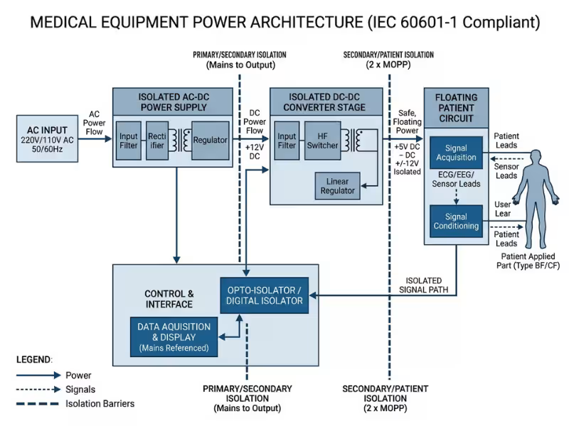
Where Isolation Sits in the Power Chain
Before you ask how strong a barrier is, ask where it sits. Its location shapes your board, spacing, and EMC plan.
The AC-DC stage carries the main barrier. Its transformer separates the outlet from everything downstream and takes full mains stress, so it usually carries the 2x MOPP rating.
DC-DC stages add local barriers. An isolated DC-DC converter can float a single rail, such as an ECG front end. It sees lower voltage but still controls patient leakage on that circuit.
Some designs need both. A bedside monitor often pairs a 2x MOPP AC-DC supply with an isolated DC-DC stage to create a floating BF or CF applied part.
Signals have to cross too. Feedback and data lines need optocouplers, digital isolators, or signal transformers rated for the barrier they bridge. One under-rated part weakens the whole line.
Placement drives the rest. Every barrier splits the PCB into zones with creepage gaps and keep-outs, and adds parasitic capacitance that sets your common-mode noise path. Sketch the barrier map before anyone draws the schematic.
Why Isolation Matters in Medical Equipment
Isolation is the part you never see and the part a test lab checks hardest. It protects patients and staff, keeps signals clean, and must keep working after something breaks.
It Keeps Leakage Current Away From the Patient
Leakage current is the small current that still crosses the barrier through transformer capacitance, Y-capacitors, and board surfaces. No barrier stops it completely.
On healthy skin, a few microamps go unnoticed. A catheter or pacing lead, however, can carry current straight to the heart, where tens of microamps may disturb its rhythm. That’s why Type CF parts allow only 10 µA in normal use, while Type B and BF parts allow 100 µA. If the barrier fails outright, mains voltage can reach the applied part.
Leakage also adds up across the supply, filter, cables, and every device on the same patient. Build a leakage budget before layout:
- List every capacitive path from mains to the patient and enclosure.
- Assign each path a share of the limit.
- Keep at least 30% margin for production spread and aging.
It Protects Clinicians and Operators
Touch current flows from the enclosure through a person to earth. IEC 60601-1 limits it to 100 µA normal and 500 µA under a single fault.
The real danger is a live chassis. If a Class I device loses its earth wire, the metal case can float toward mains voltage, and only the barrier protects the operator. A Class II supply avoids this by assuming no earth path at all.
It Keeps Low-Level Signals Clean
ECG signals measure about 1 mV, and EEG can drop to 10–100 µV. Small common-mode currents can bury them. A low-capacitance barrier gives switching noise fewer paths onto patient leads, and a floating applied part breaks ground loops between devices. For sensitive measurements, ask for barrier capacitance, not just isolation voltage.
It Stays Safe After One Thing Goes Wrong
IEC 60601-1 requires that a single fault never creates a patient hazard. That’s the real meaning of 2x MOPP: two means of protection, so one can fail while the other holds. In hardware, that means Y1 capacitors (or two Y2 in series), triple-insulated wire or certified bobbins, and wide-body isolators. If one part can bridge the barrier alone, the design isn’t single-fault safe.
The Standards and Classifications That Drive Isolation Requirements
A handful of standards and labels drive most isolation decisions. Start with the baseline, then work through the classifications that tighten it.
IEC 60601-1: The Safety Baseline
IEC 60601-1 covers basic safety (no shock, fire, or burn hazard) and essential performance (the device keeps doing its clinical job). A supply carries a component-level evaluation, usually through a CB report. Your finished device still needs end-product approval, and the supply’s report only helps if its input range, mounting, cooling, and ambient match your design.
IEC 60601-1-2 and IEC 60601-1-11
IEC 60601-1-2 covers EMC: emissions and immunity. Barrier capacitance directly shapes your common-mode noise. IEC 60601-1-11 adds home healthcare rules, with ungrounded outlets, untrained users, and 10 V/m radiated immunity versus 3 V/m in professional settings. That’s why home devices usually favor a Class II, 2x MOPP adapter.
MOPP and MOOP in Plain Terms
MOOP protects operators. MOPP protects patients and demands more. At typical mains voltages:
- 2x MOOP: Typically about 3,000 VAC and roughly 5 mm creepage
- 2x MOPP: Typically 4,000 VAC and about 8 mm creepage
A 2x MOOP supply may look “medical,” but it isn’t enough when a patient touches the device.
Type B, BF, and CF Applied Parts
- Type B: Body contact, may be earthed. 100 µA patient leakage in normal use.
- Type BF: Floating body contact. 100 µA in normal use.
- Type CF: Floating, possible cardiac contact. 10 µA normal, 50 µA single fault.
CF is the strictest and usually needs a dedicated isolated DC-DC stage. If a future version might add a cardiac lead, design for CF now.
Class I vs. Class II Equipment
A Class I device uses protective earth, leaving more room for EMI filtering. It must meet earth leakage limits, typically 5 mA normal and 10 mA single fault, and prove ground continuity. A Class II device relies on double or reinforced insulation, so Y-capacitor current has no earth path. Expect to lean on transformer shielding and careful layout.
Creepage, Clearance, and Dielectric Strength
- Clearance: Shortest path through air; guards against spikes.
- Creepage: Shortest path along a surface; guards against tracking.
- Dielectric strength: The hipot voltage the barrier survives for one minute.
Confirm all three for input-to-output, input-to-earth, and output-to-earth, and make sure screws and heatsinks don’t cut into them.
Classification | What It Means | Design Impact |
|---|---|---|
Type B | Body contact, may be earthed | 100 µA patient leakage limit |
Type BF | Floating body-contact part | Needs isolated applied part, 100 µA |
Type CF | Floating, possible cardiac contact | 10 µA limit, very low barrier capacitance |
Class I | Relies on protective earth | Earth leakage limits, continuity tests |
Class II | Double or reinforced insulation | No earth path, tighter Y-cap control |
Protection Level | Typical Use | Relative Isolation Demand |
|---|---|---|
1x MOOP | Staff-only, basic barrier | Low |
2x MOOP | Lab analyzers, operator-only equipment | Moderate |
1x MOPP | Single patient-protection barrier | Moderate to high |
2x MOPP | Patient-contact devices, mains-facing supplies | Highest |
The Main Isolation Methods and Where They Fit
Three technologies do most of the work. Choose by asking what must cross the barrier and what happens to the patient if the part degrades.
Transformers
Transformers carry the main barrier in almost every AC-DC supply and isolated DC-DC converter. Nothing else practically moves real power across 2x MOPP. Their weakness is interwinding capacitance, often 20–50 pF. For tight leakage targets, ask for a shield winding or split bobbin.
Optocouplers
Optocouplers usually carry output feedback across the barrier. Wide-body packages commonly offer 8 mm or more of creepage. Their weakness is aging: current transfer ratio drops over time, faster when hot. Leave loop margin and add independent overvoltage protection.
Digital and Capacitive Isolators
Digital isolators pass fast data between a floating front end and the processor. They stay stable over life and typically add only 1–2 pF. Confirm reinforced certification under IEC 60747-17, enough package creepage, and a suitable working voltage.
Basic vs. Reinforced Isolation in Real Designs
The method doesn’t set the protection level. The rating does. Pair a reinforced transformer with a basic optocoupler, and you have a basic barrier. Check every crossing part against the insulation diagram.
Method | Best For | Main Strength | Main Limitation |
|---|---|---|---|
Transformer | Power transfer, main mains barrier | Moves real power across 2x MOPP | Interwinding capacitance adds leakage |
Optocoupler | Feedback and slow control signals | Simple, wide creepage packages | Output drifts as the LED ages |
Digital isolator | Fast data from patient front ends | Fast, stable, very low capacitance | Ratings and package spacing vary |
Reinforced rating | Patient-facing barriers | Two protection levels in one system | Every crossing part must match it |
How to Read an Isolated Medical Power Supply Datasheet
A datasheet’s front page shows the best results under the friendliest conditions. I read datasheets from the back, starting with the footnotes. For a shorter checklist view, this guide to medical power supply datasheet specs is a useful companion.
Isolation Voltage Is Not the Whole Story
Find out which barrier the headline number describes:
- Input to output: For 2x MOPP, look for 4,000 VAC.
- Input to ground: Often 1,500 VAC, matching 1x MOPP.
- Output to ground: Sometimes only 500 VAC, which matters for floating applied parts.
Separate test voltage from working voltage, often 250 VAC. Watch for VDC ratings (5,600 VDC roughly equals 4,000 VAC), one-second production tests versus one-minute type tests, and high voltages with no “2x MOPP” label.
Leakage Current Specs Need Context
Check touch current, earth leakage for Class I, and patient leakage if the output feeds an applied part. Labs test at 110% of the highest rated input, usually 264 VAC at 60 Hz. A figure listed at 230 VAC and 50 Hz can understate the lab result by roughly a quarter. Also compare normal and single-fault values. Ultra-low leakage usually means less Y-capacitance, so ask for EMI data in the same configuration.
Input, Output, Hold-Up, and Inrush Still Matter
- Input range: Typically 90–264 VAC; DC-DC ranges should cover a drained battery.
- Regulation and ripple: Look for ±1–2% and note ripple bandwidth.
- Hold-up time: Often 10–20 ms, but ask for the figure at 100 VAC and full load.
- Inrush: Often 30–60 A briefly. Several devices on one cart breaker can trip it.
Efficiency, Thermal Behavior, and Derating
A 100 W supply at 90% efficiency dumps about 11 W into your enclosure; at 94%, about 6 W. Many open-frame ratings assume 10–20 CFM of airflow, and convection ratings often run 30–40% lower. Read the derating curve at your real internal temperature, commonly starting near 50 °C, and check the altitude rating.
EMC and Approvals: Check the Scope, Not the Logo
Look for CISPR 11 emissions data, ideally Class B, plus immunity results. Ask whether the supply needs an external filter, which adds parts and often leakage. Request the full CB report to IEC 60601-1 Edition 3.1 or later and verify the certificate online. Remember that a component approval doesn’t approve your device, and a marketing sheet isn’t the certificate. One “fully certified” supply’s report covered only the open-frame version, while the customer had ordered the enclosed model.
How to Choose the Right Isolated Medical Power Supply
Many teams filter by wattage first. A better approach is the opposite order, because wattage is easy to adjust late, while protection level is not.
Start With Patient Contact, Not With Wattage
List every applied part and its contact type: earthed body contact (Type B), floating body contact (BF), or any path to the heart (CF). Then rate the risk: contact duration, wet or broken skin, and whether the patient can pull away. Design for the strictest case your roadmap might need.
Match the Required Protection Level
Use 2x MOPP for any supply between mains and a patient, and 2x MOOP only for staff-only equipment. Defaulting to 2x MOPP protects you if a patient sensor arrives later.
Then choose Class I for grounded hospital carts and imaging systems, or Class II for home and portable devices. Home use also brings IEC 60601-1-11 and higher immunity levels. Browse certified medical power supplies once these inputs are set.
Check the Full Fit, Not Just the Electrical Fit
- Form factor: Include creepage to the chassis.
- Thermal limits: Sealed cases often run 15–20 °C hotter; use convection ratings.
- Cabling: Use keyed connectors and strong strain relief.
- Enclosure integration: Check mounting-hole grounding and inlet alignment.
- EMC risk: Confirm whether an external filter is needed.
Drop the supply’s 3D model into your CAD file on day one.
Verify Documentation Before Design Freeze
Request a current certificate and the full CB report covering your exact model, input range, mounting orientation, cooling, and ambient. Confirm the edition and verify the number in the IECEE database. A report limited to horizontal mounting can force new thermal work if you mount vertically.
Plan System-Level Validation Early
Measure system leakage on the first prototype with every cable and accessory connected, at 264 VAC and 60 Hz, including while charging. Run bench EMC scans targeting 6 dB of margin, and review creepage and thermal data before cutting enclosure molds.
Selection Step | What to Confirm | Common Risk If Missed |
|---|---|---|
Patient contact | Every applied part, B/BF/CF rating | Late CF change forces new isolation stage |
Protection level | 2x MOPP vs. 2x MOOP, Class I or II, environment | Supply fails patient-protection review |
Full fit | Space, thermal rating, cabling, enclosure, EMC | Overheating, lost creepage, emissions failure |
Documentation | Certificate, report scope, edition, database check | Certificate doesn’t cover your configuration |
System validation | System leakage, bench EMC margin, review before tooling | Failed lab visit, board spin, mold rework |
Design Priorities Change by Application Scenario
The isolation rules stay the same. What changes is which rule you can least afford to miss.
Patient-Monitoring and Body-Contact Devices
Use a 2x MOPP mains supply, then float each applied part with its own isolated DC-DC stage. For ECG front ends, look for converters under about 10 pF and digital isolators on data lines. Check that cable shields and debug ports don’t quietly ground the floating side.
Home Healthcare Devices
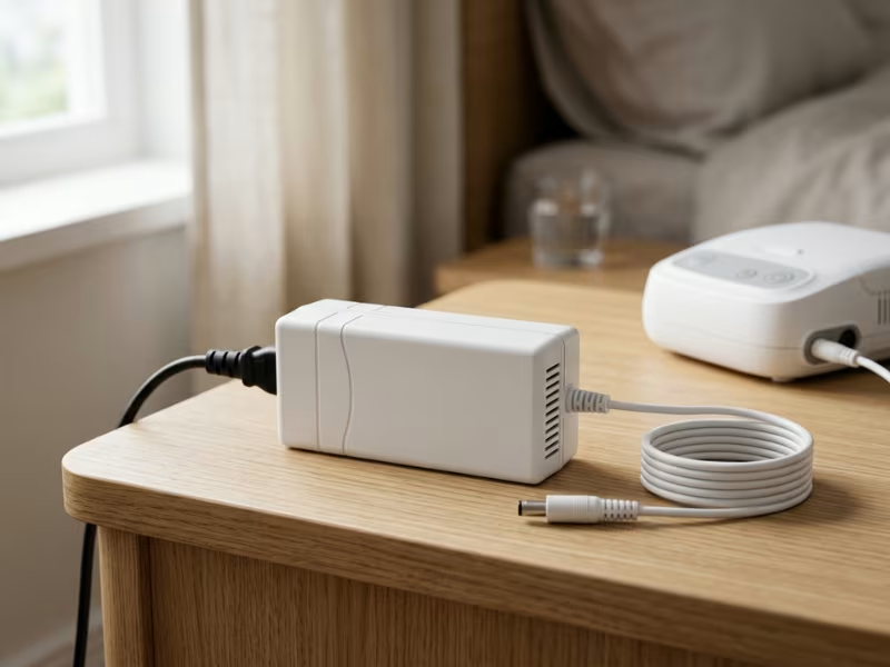
At home, you control nothing: not the outlet, the extension cord, or who plugs in what. A Class II external adapter with 2x MOPP is usually the safest choice, because it keeps mains outside the enclosure and lets patients swap it easily. When you need a specific connector, cable length, or output combination, custom power adapters make integration cleaner. Use a keyed DC connector, and ask for a shielded transformer with real EMC margin to meet 10 V/m immunity.
Portable and Compact Devices
An 8 mm creepage gap doesn’t shrink with the case. Many teams move the main barrier into a 2x MOPP external charger and use a small isolated DC-DC stage for the applied part. Test leakage while the device charges and runs, and confirm the DC-DC range covers a drained cell.
High-EMC-Risk or Measurement-Sensitive Equipment
EEG systems and devices near electrosurgery handle 10–100 µV signals, so the supply often sets the noise floor. Define essential performance in numbers, such as “noise stays below 5 µV during radiated immunity.” Choose low barrier capacitance over extra kilovolts, and test with a signal simulator logging the trace.
Mistakes That Delay Certification or Force a Redesign
Most redesigns come from one unchecked assumption. These six show up again and again:
- Picking an isolated supply that isn’t medical-grade. An IEC 62368-1 unit can measure 300 µA touch current against a 100 µA limit. Get the IEC 60601-1 CB report before it enters your BOM.
- Reading 2x MOOP as 2x MOPP. One letter separates roughly 3,000 VAC and 5 mm from 4,000 VAC and 8 mm.
- Budgeting leakage for the supply alone. A 60 µA supply plus filter, Wi-Fi module, and USB cable can land at 115 µA.
- Trusting the headline isolation voltage. Check all three barriers and the working voltage.
- Designing for the hospital, then selling for the home. Home use brings two-prong outlets and IEC 60601-1-11.
- Swapping in a “commodity equivalent” late. Treat any supply change as a design change and rerun leakage, hipot, and EMC checks.
Each takes about an hour to catch on paper and a board spin to fix in hardware.
Testing, Verification, and Ongoing Compliance
A passed report proves safety on test day, not for the next 10,000 units. Compliance has two phases.
Type Testing and System Validation
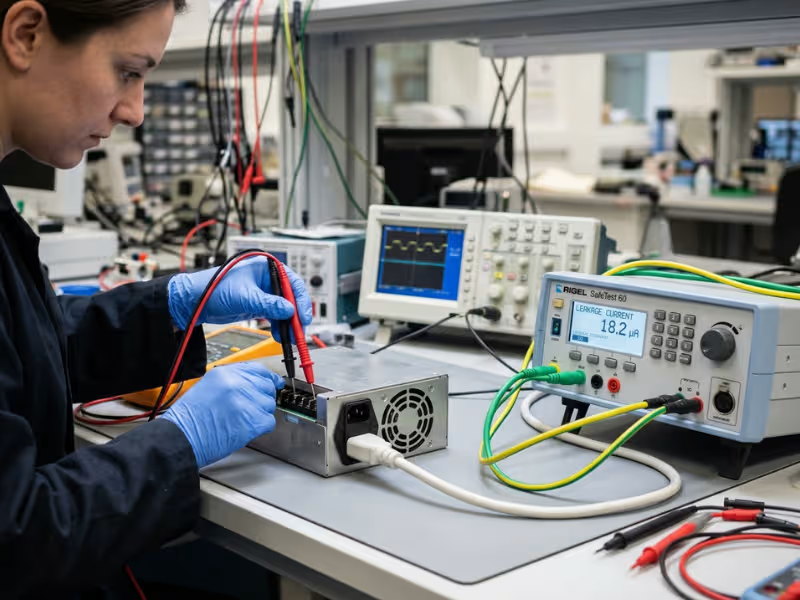
The lab applies full dielectric withstand voltage for one minute, often after humidity preconditioning. Leakage is measured at 110% of rated input under normal and single-fault conditions. If your bench data sits within 10% of a limit, expect trouble. Abnormal operation tests, such as blocked vents and shorted outputs, often reveal missing protection circuits.
Production Testing and Change Control
A good factory runs hipot on 100% of units, commonly for one to three seconds, plus earth continuity for Class I products and a functional check. Any new transformer vendor, Y-capacitor, optocoupler, or factory needs review against the CB report. Insist on written PCNs, typically at least six months ahead, and keep a traceable critical components list.
FAQs
What is the difference between an isolated and a non-isolated power supply?
An isolated supply uses a transformer so no copper path links mains to the load. A non-isolated supply shares a conductor between input and output. Non-isolated stages work downstream of a proper barrier, never as the only protection.
How much isolation voltage does a medical power supply need?
At typical mains voltages up to 250 VAC, 2x MOPP calls for 4,000 VAC, 1x MOPP for 1,500 VAC, and 2x MOOP typically about 3,000 VAC. Check input-to-ground and output-to-ground ratings too.
What is 2x MOPP, and when is it required?
It means two means of patient protection, typically 4,000 VAC isolation and about 8 mm creepage. You need it whenever a patient touches the device or connects through an applied part.
Can I use a standard power supply in a medical device?
Sometimes, but it usually needs added isolation, insulation, or protective earth, plus full system testing. For devices with applied parts, a certified medical supply usually costs less overall.
What is the difference between Type B, BF, and CF applied parts?
Type B may be earthed and Type BF floats; both allow 100 µA patient leakage in normal use. Type CF covers possible cardiac contact and allows only 10 µA.
What standards apply to home-use medical power supplies?
IEC 60601-1, IEC 60601-1-2, and IEC 60601-1-11, plus ANSI/AAMI ES60601-1 for the US. Most home devices use a Class II, 2x MOPP adapter with a keyed connector.
Conclusion
Every isolated medical power supply decision starts with two answers: what touches the patient, and which standard applies. Those answers set your MOPP level, leakage budget, and Class I or II choice. Wattage comes later.
Changing an isolation decision on paper takes an afternoon. Changing it after layout freeze often costs a board spin and a lost quarter. Treat the supply as a safety component, not a commodity part.
Your next step: Mark every barrier on an insulation diagram, then run leakage and pre-compliance EMC checks before layout freeze. To connect isolation choices to real device settings, explore these application examples.