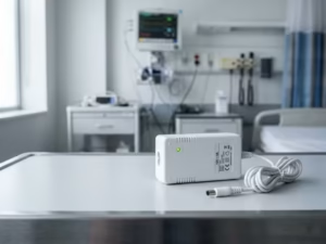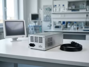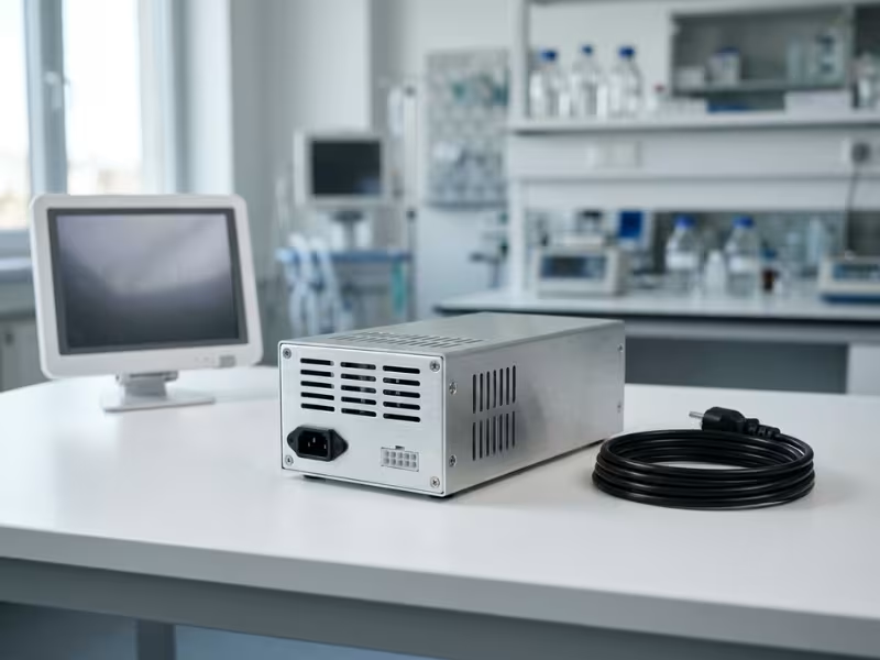
Many engineers pick a medical power supply the way they pick any other part. They check wattage, size, and price. Then the trouble starts.
A medical power supply is not a simple component choice. Device class, patient contact, use environment, EMC, and reliability all shape the right answer. Treat it as a system decision, not a line item on the BOM.
I have watched solid designs stall because of the wrong supply. The device fails EMC testing. Leakage current climbs past the limit. Certification slips by months, and the team pays for rework nobody planned.
In this guide, I share the selection order I use with design teams. It starts with device context. Then it moves through protection level, real electrical load, environment, and lifecycle support.
We will focus on AC/DC medical power supplies. That keeps the advice specific and ready for your next design review.
Start With the Device Context, Not the Datasheet
When a team sends me a datasheet and asks, “Will this one work?”, I set it aside first. The real answer lives in the device, not in the spec table. Before I compare a single wattage figure, I want to know what the product does, who touches it, and where it runs.
That context filters the market fast. It turns hundreds of catalog options into a shortlist you can actually test.
Three Questions That Define the Shortlist
I ask the same three questions at every first design review. Each one rules out whole groups of supplies before anyone opens a price list.
1. Will the device contact the patient?
This question sets your isolation target and leakage limits. A lab analyzer that never touches anyone sits in a very different place than an ECG lead on a patient’s chest. If any part touches the body, or might through a cable or probe, plan for stricter isolation from day one.
2. Where will people use it: hospital, home, or transport?
A hospital gives you reliable grounding and trained staff. A home gives you old wiring, cheap extension cords, and humid bathrooms. An ambulance adds vibration, temperature swings, and vehicle power. Each setting shifts your EMC levels, input range, and mechanical demands.
3. What happens if power dips, resets, or turns noisy?
For a bedside thermometer, a reset is an annoyance. For an infusion pump mid-dose, it is a hazard. Write down the worst outcome you can accept. That answer sets your hold-up time, battery backup, alarm power, and rail noise targets.
Why This Order Matters
Many teams flip this sequence. They pick a supply early for cost or size, then try to build the safety case around it. That approach usually backfires.
A medical power supply becomes part of your certified system. Your safety, leakage, and EMC results reflect that exact supply. Swap it late, even for a “drop-in” part with the same certificate, and you may reopen your risk file and rerun tests.
I tell clients to treat the supply like the battery or the main sensor. It deserves a documented design decision, not a last-minute price comparison after layout freezes.
Step 1: Set Your Safety and Regulatory Baseline
Once you know the device context, find out how strict your regulatory path will be. This step does not hand you a power supply spec. It tells you how much proof you need, and how much of it must come from your supplier.
Your Device Class Sets How Much Proof You Need
In the US, the FDA sorts devices into Class I, II, or III. In Europe, the MDR uses Class I, IIa, IIb, and III. Higher classes mean higher patient risk and closer scrutiny.
Here is the part many engineers miss. Device class does not map directly to a power supply rating. A Class II device does not need a “Class II power supply.” Instead, the class shapes three things around your supply:
- Evidence depth. Higher-risk devices need a deeper paper trail. Expect to justify why you chose this supply and how it fits your risk file.
- Validation rigor. Class IIb and III devices face more test cases, wider margins, and closer review of failure modes.
- Supplier requirements. Auditors look harder at your vendor. Do they run an ISO 13485 quality system? Can they support validation and controlled production from qualified facilities? Will they send formal notices before they swap a capacitor or move a production line?
Write down your likely device class before you contact vendors. Then ask each one how they support customers at that level.
A Supply Certificate Is Not Device Approval
This point saves teams the most pain.
A supply with an IEC 60601-1 certificate or CB report has passed testing as a component. That cuts your test load and gives your lab a trusted starting point. It does not certify your device.
Your lab still evaluates the complete system. It measures leakage on the finished device, with every cable, Y-capacitor, and accessory in place. It tests EMC on the whole product. A supply that passes emissions alone can still fail once its cables run next to a motor driver.
Read the “conditions of acceptability” in the supply’s report, too. These notes list the mounting, airflow, ambient, and grounding limits the certificate depends on. If your enclosure breaks one, part of that certificate stops helping you.
Also, review any “FDA approved” claim on a power supply datasheet carefully. The FDA clears or approves devices, not standalone power supplies.
The Standards That Raise the Bar First
You don’t need to memorize the IEC 60601 family. You need to know which standards tighten your power supply choice.
- IEC 60601-1 is the core safety standard. It defines insulation, creepage, MOOP, MOPP, and leakage limits.
- IEC 60601-1-2 covers EMC. It often decides whether a cheaper supply survives or forces late filtering.
- IEC 60601-1-11 applies to home and other non-professional settings. It raises the bar on ingress protection, rough handling, and lay users.
- Particular standards (the “-2-” series) cover infusion pumps, ventilators, ECG monitors, and more. They can add rules for alarm power, supply interruption, and battery handoff, and they often override the general standard.
Step 2: Decide the Required Protection Level
With your baseline set, you can answer the question that shapes your shortlist most: how much protection does your device actually need?
Getting it wrong costs money either way. Aim too low, and you fail safety testing. Aim too high, and you pay for a bigger supply and fight thermal problems you never needed.
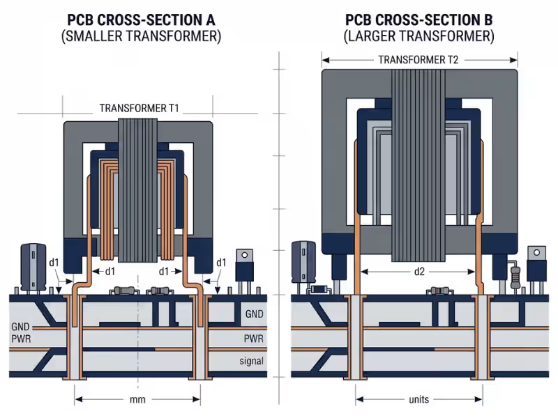
MOOP vs. MOPP, Without the Jargon
MOOP (Means of Operator Protection) protects the person using the device, such as a nurse or lab technician. They touch the enclosure and controls, not electrodes. MOOP looks a lot like IT equipment safety rules.
MOPP (Means of Patient Protection) protects the patient. Patients may be sedated or wired to sensors, and they often can’t pull away from a shock. So MOPP asks for more.
At 250 VAC working voltage, typical figures look like this:
- 2xMOOP: 3,000 VAC isolation test, about 5 mm creepage
- 2xMOPP: 4,000 VAC isolation test, about 8 mm creepage
That extra spacing explains why 2xMOPP supplies often run larger and cost more.
When You Actually Need 2xMOPP
Many teams default to 2xMOPP “just to be safe.” Sometimes that’s smart. Sometimes it wastes space. Here’s how I sort it out by scenario.
The device never contacts the patient. Think of a centrifuge or a pharmacy cabinet. 2xMOOP often works. Check your risk analysis first, though. If an operator might touch the device and a patient at once, your lab may still push for MOPP.
The device touches the skin. Surface electrodes, BP cuffs, and SpO2 clips all count as applied parts. You need 2xMOPP between mains and that part. A supply that provides 2xMOPP on its own keeps the design simple.
The device creates a floating patient circuit. ECG front ends isolate the patient side from earth. You can split protection, with one MOPP in the supply and one in an isolated DC/DC stage. That works, but it adds design effort and paperwork.
The device sits near the heart. Catheter systems and intracardiac monitoring fall here. 2xMOPP is the floor. You will almost always add a dedicated isolation barrier on the patient circuit.
My rule: decide where your isolation lives before you pick the supply. The supply is one barrier in a chain.
Type B, BF, and CF Change the Leakage Conversation
Applied part type ties protection level to leakage limits, so treat them as one decision. The BF-to-CF jump matters most. Normal-condition patient leakage drops from 100 µA for BF to 10 µA for CF. A tenfold cut changes your whole architecture.
Applied Part Type | Typical Use | Isolation Implication | Selection Note |
|---|---|---|---|
Type B | Patient tables, some lights, non-floating contact parts | Applied part may connect to earth | A 2xMOPP supply usually covers it; check enclosure touch current |
Type BF | ECG surface electrodes, BP cuffs, SpO2 sensors, ultrasound probes | Floating applied part, isolated from earth | Choose a low-leakage 2xMOPP supply; leave margin for cables and accessories |
Type CF | Intracardiac catheters, direct heart contact | Floating part with very strict leakage limits | Plan a dedicated patient isolation barrier; the supply alone won’t reach 10 µA |
Budget Leakage Current Early
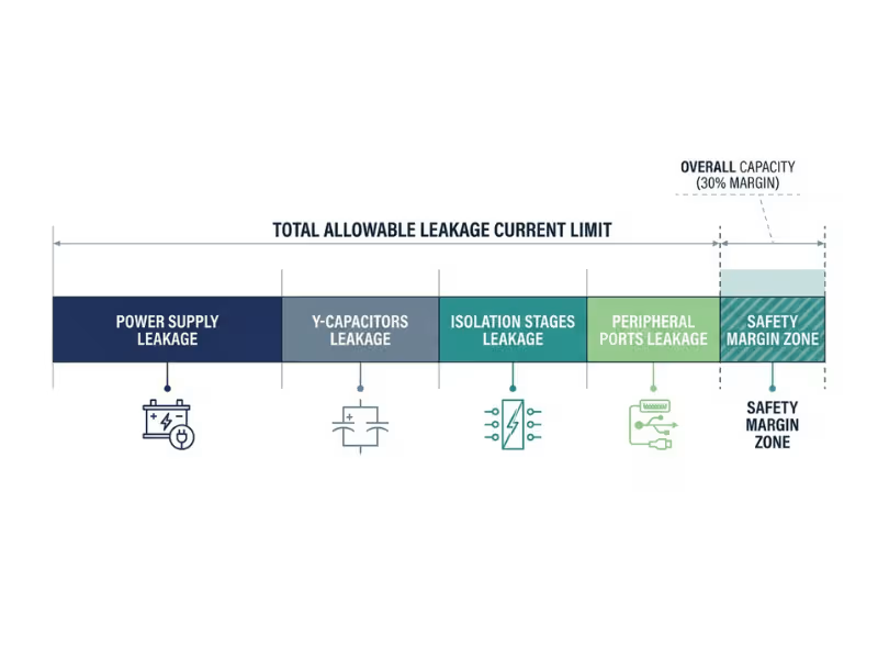
Teams pick a supply rated for “under 100 µA leakage” and assume they’re done. Then the finished device fails touch current at the lab. Several parts draw from the same budget:
- Y-capacitors. A single 1 nF Y-cap at 264 VAC and 60 Hz passes roughly 100 µA on its own.
- Isolation structures. Every transformer and isolated converter adds stray capacitance across its barrier.
- Peripheral interfaces. USB, Ethernet, and nurse-call lines create new paths, especially when they connect to a grounded PC.
Build a simple leakage budget during architecture. List every source and estimate its share. Keep at least 30% margin, because labs test at 110% of rated mains and under single-fault conditions. Catch it early, and you trade a Y-cap for better layout. Catch it late, and you trade it for a respin.
Step 3: Match the Power Supply to the Real Electrical Load
Protection level tells you which supplies are allowed. Load analysis tells you which ones will actually work. Your goal: describe what the device draws from second to second, not just on average.
Continuous Power Is Only the Starting Point
Build a load profile instead of a single number. List each subsystem, its typical draw, its worst-case draw, and how long each state lasts. A monitor that averages 40 W may briefly hit 90 W when the display, radio, and charger wake at once. Then add 20–30% headroom over the true worst-case continuous load.
Check Peak Loads, Startup Behavior, and Duty Cycle
Some medical loads arrive in bursts the average never shows:
- Blowers and motors can pull two to three times running current while accelerating.
- Heaters switch on hard and stay on for long stretches.
- RF bursts from radios and therapy stages draw short, high pulses.
- Charge pulses from defibrillator capacitors and fast chargers repeat often.
A continuous rating does not mean a supply can handle these pulses. Peak ratings, such as 150% for a few seconds, come with strict duration and duty cycle limits. Exceed them and the supply folds back, hiccups, or slowly cooks its capacitors.
Startup needs its own check. Large bulk capacitors can look like a short at power-on. Ask for the maximum capacitive load, then test a cold start at low line and low temperature.
Hold-Up Time, Brownout Behavior, and Battery Handoff
Mains power isn’t perfect. Generators switch over, and voltage sags when big loads kick on.
Hold-up time often reads 10–20 ms on datasheets, but vendors usually measure it at high line. At 100 VAC, it can drop sharply. Brownout behavior matters just as much. A supply that chatters on and off during a sag will reset your processor repeatedly, so ask for turn-on and turn-off thresholds and their hysteresis. Battery handoff must finish before hold-up runs out, with the rail staying above your processor’s brownout threshold.
Ripple, Noise, and Regulation for Sensitive Circuits
ECG, SpO2, and ultrasound front ends work with tiny signals. Check how the vendor measured ripple, since a 20 MHz bandwidth limit can hide spikes your front end still sees. Look at transient response, too. A motor starting on a shared rail can drag down your ADC reference. For sensitive channels, add a post-regulator or LDO.
Ask What Failure Mode You Can Accept
Many devices don’t need power that never fails. They need power that fails safely. Ask your team:
- Can the device reboot safely? Fine for a scanner. A hazard for a pump mid-dose.
- Must alarms stay active? Many particular standards require it during supply failure.
- Is there battery takeover? Define the window and test it at worst-case load.
- Will noisy rails affect sensing accuracy? A wrong reading can cause more harm than none.
Electrical Parameter | Why It Matters | Often Missed by Buyers |
|---|---|---|
Continuous output power | Sets baseline sizing | Derating at real ambient temperature |
Peak power rating | Covers motors, heaters, RF bursts | Duration and duty cycle limits |
Max capacitive load | Ensures clean startup | Cold start at low line voltage |
Hold-up time | Covers brief mains dropouts | Measured at high line, not 100 VAC |
Brownout thresholds | Prevents repeated resets | Hysteresis between turn-on and turn-off |
Ripple and noise | Protects sensing accuracy | Measurement bandwidth hides spikes |
Transient response | Keeps rails stable during load steps | Shared rails with motor loads |
Step 4: Choose the Right Form Factor and Cooling Strategy
Your load profile tells you how much power you need. Your mechanical design decides how much you can actually use. The shape you pick sets your heat path, and the heat path sets your real output.
Open Frame, Enclosed, or External Adapter?
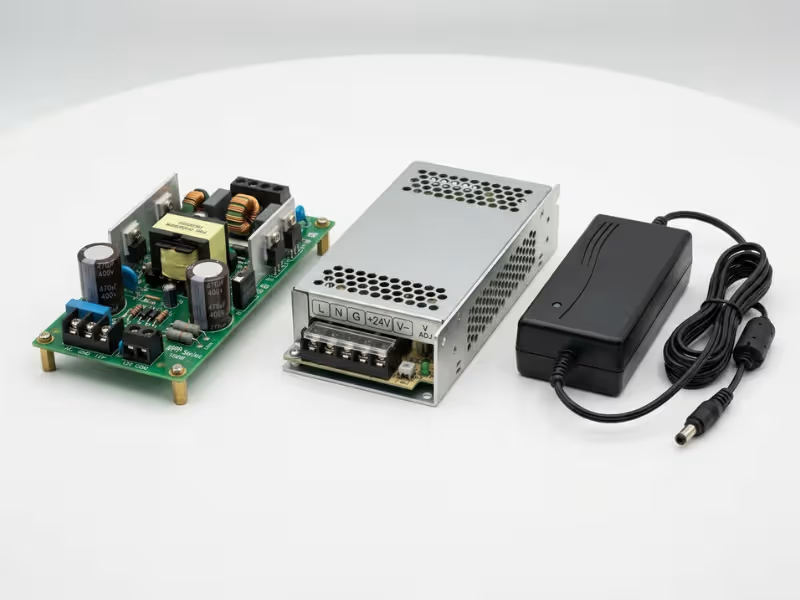
Open frame supplies suit devices with a solid chassis, such as monitors and analyzers. They cost less, but your enclosure becomes their fire and shock barrier, and you own the airflow.
Enclosed supplies add a metal cover and often a fan. They fit carts and larger diagnostic systems, with less integration work and more space used.
External adapters move mains voltage out of the device. That simplifies your safety case, cuts internal heat, and can ease your leakage budget. A 2xMOPP Class II adapter is often the fastest route through home-use requirements.
When a Configurable Supply Makes Sense
Imaging systems and lab automation often need four to six rails. A configurable supply lets you choose each rail from standard modules under one safety certification. I recommend it for three or more isolated rails, moderate volumes, or power needs that may shift before production. For two rails, a standard supply plus a DC/DC converter usually costs less.
Cooling, Airflow, and Derating Inside the Enclosure
Many medical supplies deliver full power up to 40–50°C, then lose about 2–2.5% per degree. Cooling matters too. A supply might deliver 600 W with 15 CFM of forced air but only 400 W with convection.
Air near the supply often runs 15–20°C above room temperature. In a 40°C room, your supply may breathe 60°C air. A 600 W supply on paper may not be a 600 W supply in a sealed enclosure at the device’s real ambient temperature. You might have 450 W to work with.
Put a thermocouple next to the supply on your first prototype and run it at maximum load and room temperature. Think hard before adding a fan, since it adds noise, dust, and a failure mode. And remember that electrolytic capacitor life roughly halves with every 10°C rise.
Step 5: Adjust for the Use Environment
A supply that works well on a hospital cart can struggle in a living room or ambulance. The load stays the same. Everything around it changes.
Clinical, Home, and Transport Environments Are Not Equal
Hospitals offer grounded outlets, stable mains, and trained staff. The risks come from nearby surgical gear and daily wipe-downs with strong disinfectants.
Home healthcare is harder than most teams expect. Outlets may lack a working ground. Users drop adapters and use cheap power strips. Under IEC 60601-1-11, I steer home devices toward Class II supplies, strong strain relief, and a 90–264 VAC input with good surge tolerance.
Transport adds vibration, temperature swings, and inverter power. Some inverters output a modified sine wave that stresses the input stage. If transport is in scope, check IEC 60601-1-12 early.
EMC Risk Changes With the Environment
Two differences catch teams most often:
- Emissions. Home devices usually need CISPR 11 Class B, which is stricter than Class A.
- Radiated immunity. Home use raises the test level from 3 V/m to 10 V/m.
Ask vendors for emissions data with at least 6 dB of margin below the Class B limit. Your cables and motor drivers will eat some of it.
Shock, Vibration, Humidity, Altitude, and Cleaning Exposure
- Drops: Heavy transformers and capacitors on open-frame boards can crack solder joints.
- Vibration: Transport calls for secured magnetics and locking connectors.
- Humidity: Look at conformal coating and rated humidity range.
- Altitude: IEC 60601-1 assumes 2,000 m. Above that, you need larger creepage and clearance, so confirm the altitude rating in writing.
- Cleaning: Alcohol and quaternary cleaners crack some plastics. Ask how the vendor tested adapter housings.
Step 6: Selection Priorities by Device Type
The first five steps give you a method. This step shows how it plays out on real products. If your device isn’t listed, start with the closest match in load profile and patient contact.
Patient Monitors and Portable Diagnostics
Monitors live or die on signal quality. Switching noise can show up as a jagged baseline or a false arrhythmia alarm.
Map every sensor port first. Surface ECG, SpO2, and NIBP usually land at Type BF, while a cardiac path moves you to CF. Ask whether the supply drops into burst mode at light load, since that can put noise right in your measurement band. Portable units often do better with an external 2xMOPP adapter. Also test the device while it charges and measures at once.
Infusion and Syringe Pumps
A pump doesn’t need much power. It needs power it can count on.
Battery handoff is the core requirement. Test the transfer with the motor stepping and the display at full brightness. Ask for hold-up data at 100 VAC. Give the alarm circuit its own backup source, such as a supercapacitor, so a dead battery can’t silence it. Pumps stack on poles, so pick compact 20–60 W supplies and confirm they still meet 2xMOPP creepage.

Ventilators and Anesthesia Systems
These are the toughest loads on the list. Size for the blower, not the average. Turbines can draw two to three times running current on each breath, and valves and humidifiers add more. Test with real breathing patterns.
Plan for 24/7 operation, with capacitor life at real internal temperature and fan life against your service interval. Keep alarm power separate from therapy power. For anesthesia systems, include the supply’s location near oxygen-enriched zones in your fire risk analysis.
Imaging and Diagnostic Systems
Patient contact is often limited, but the electrical system is large and noise-sensitive. Expect five or more rails and power from hundreds of watts to several kilowatts. Configurable or N+1 modular setups earn their cost here.
Treat EMC as a system problem, including harmonics and inrush. Switching harmonics can show up as streaks in an image, so ask whether the supply can sync to an external clock.
Home Healthcare Devices
Read IEC 60601-1-11 before you shortlist. Use a Class II adapter strategy, since many homes lack reliable earth. Design for misuse with a keyed DC connector and strong strain relief on both cable ends. Test with a cheap power strip and a nearby appliance switching on.
Wearables and Body-Contact Devices
Wearables stay on skin for hours, so leakage budgets get very tight. If users can wear the device while charging, the charger joins the patient circuit. I push for “no charging while worn” whenever clinical use allows it.
IEC 60601-1 limits long-contact applied parts to about 43°C. Keep charge rates modest and measure the hottest point on the housing. Pick fanless, quiet chargers, since coil whine on a nightstand generates support calls.
Quick Reference: Priorities by Device Type
Device Type | What Matters Most | Common Power Mistake |
|---|---|---|
Patient monitors and portable diagnostics | Low noise, correct BF/CF level, charge-while-measuring behavior | Ignoring burst-mode noise at light load |
Infusion and syringe pumps | Battery handoff, alarm continuity, compact size | Testing handoff at idle instead of full load |
Ventilators and anesthesia systems | Peak load capacity, reliability, independent alarm power | Sizing for average draw instead of blower peaks |
Imaging and diagnostic systems | Multi-rail flexibility, system-level EMC, clean rails | Letting switching harmonics reach the image chain |
Home healthcare devices | IEC 60601-1-11, Class II design, misuse resistance | Assuming a grounded outlet and stable mains |
Wearables and body-contact devices | Ultra-low leakage, skin temperature limits, quiet charging | Allowing charging while worn without a leakage plan |
Common Mistakes That Cause Rework
Most rework comes from reasonable assumptions that nobody checked in time. Here are the six I see most.
1. Choosing by price before protection level
What teams assume: Same wattage means interchangeable parts.
What actually happens: The cheap part only offers 2xMOOP. Once the risk analysis confirms a BF applied part, the team adds an isolation stage or swaps the supply, and the savings vanish in the respin.
2. Treating a 60601 certificate as full device approval
What teams assume: The supply is certified, so testing is mostly done.
What actually happens: The lab tests the finished device, cables and all. Break the conditions of acceptability, and part of the certificate stops covering you.
3. Ignoring peak load and brownout behavior
What teams assume: The continuous rating covers it.
What actually happens: A blower spin-up triggers hiccup mode, and sags reset the processor. These failures rarely appear on a resistive bench load.
4. Forgetting the leakage budget until late validation
What teams assume: The supply’s leakage spec leaves plenty of room.
What actually happens: Y-caps, a second barrier, and a USB port push the total over the limit weeks before submission. Removing filter parts then reopens EMC testing.
5. Using nominal power without thermal derating
What teams assume: A 300 W supply easily handles 250 W.
What actually happens: In 60°C internal air, it derates to about 220 W. It trips at peak load or ages its capacitors fast.
6. No lifecycle, PCN, or second-source plan
What teams assume: The vendor will build this part for as long as the device sells.
What actually happens: Devices sell for 7–10 years, while supply lines change faster. A silent component swap or short end-of-life notice can trigger re-verification. Ask for a written PCN policy and qualify an alternate early.
A Practical Medical Power Supply Selection Checklist
Fill in each line before you request quotes. Then send the same list to every vendor.
- Device type and patient contact level: List every applied part as B, BF, or CF. The strictest one sets the bar.
- Intended environment: Hospital, home, transport, or mixed. Note worst-case temperature, humidity, altitude, mains quality, and cleaning agents.
- Required standards: IEC 60601-1 and -1-2, plus -1-11 for home and -1-12 for EMS, plus every particular standard.
- MOPP/MOOP target: Choose 2xMOOP or 2xMOPP and record where each barrier sits.
- Leakage budget: Assign shares to the supply, Y-caps, isolation stages, and ports. Keep 30% margin at 110% mains under single fault.
- Continuous, peak, standby, and hold-up needs: Build a load profile, record peak size and duty cycle, and set hold-up at 100 VAC.
- Form factor and cooling limits: Measure air temperature next to the supply and check it against the derating curve.
- EMC and pre-compliance plan: Confirm emissions class and immunity levels. Ask for 6 dB of margin and scan your first prototype.
- Documentation and lifecycle support: Request the CB report, EMC report, ISO 13485 proof, PCN policy, and last-time-buy terms.
Vendors who answer items 5, 8, and 9 clearly and quickly tend to support you well after launch.
FAQs
What makes a medical power supply different from a standard ITE supply?
ITE supplies follow IEC 62368-1, which protects office users. Medical supplies follow IEC 60601-1, which assumes a patient who may not be able to react. That means thicker insulation, wider creepage, higher test voltages, lower leakage, and tougher EMC immunity.
Do all patient-contact devices need 2xMOPP?
They need two means of patient protection between mains and the patient, but not necessarily inside the supply. A 1xMOPP supply plus a properly rated isolated DC/DC stage can work. Your lab looks at the whole path from wall to patient.
Can I use an industrial power supply in a medical device?
You can, but it rarely saves money. You typically add an isolation stage and prove the full system meets IEC 60601-1, and you lose the component certification that shortens testing. Non-medical equipment can sit outside the patient environment with proper separation, but that doesn’t apply to the supply inside the device.
How early should leakage current be budgeted?
Start as soon as you know your applied part type, before the schematic freezes. Update it with every new Y-cap, port, or cable, and measure it on your first powered prototype.
Does home use change the power supply requirements?
Yes. IEC 60601-1-11 adds requirements for ingress, rough handling, and lay users. Expect stricter emissions and immunity levels, ungrounded outlets, and users who lose or swap adapters. Battery devices that charge from mains still fall under these rules.
Is an external adapter better than an internal supply?
It depends on power and use. External adapters work well below about 150 W for portable, home, and wearable devices. Internal supplies suit higher power, cart-mounted systems, and sealed housings, and they remove the risk of a wrong charger.
What documents should I request from a supplier?
Ask for the full IEC 60601-1 CB report, the IEC 60601-1-2 EMC report, risk management inputs for ISO 14971, ISO 13485 certification, derating and leakage data, MTBF or capacitor life calculations, RoHS and REACH declarations, and the written PCN and end-of-life policy. Note how quickly the vendor delivers them.
Get the Order Right, and the Choice Gets Easier
A good medical power supply choice follows a clear order: device context, protection level, real load, environment, then lifecycle support. Each step narrows the field for the next.
Projects rarely stall because someone got the wattage wrong. They stall because the team chose 2xMOOP when the device needed 2xMOPP. Or they skipped the leakage budget. Or they assumed a grounded outlet in a home, or let a component certificate stand in for system validation.
Your next step is simple. Take the checklist and use it to compare two or three shortlisted options, whether from your current vendors or a broader range of power supply products. Line up protection level, leakage data, EMC margin, and PCN policy side by side. Compare unit price only after that.