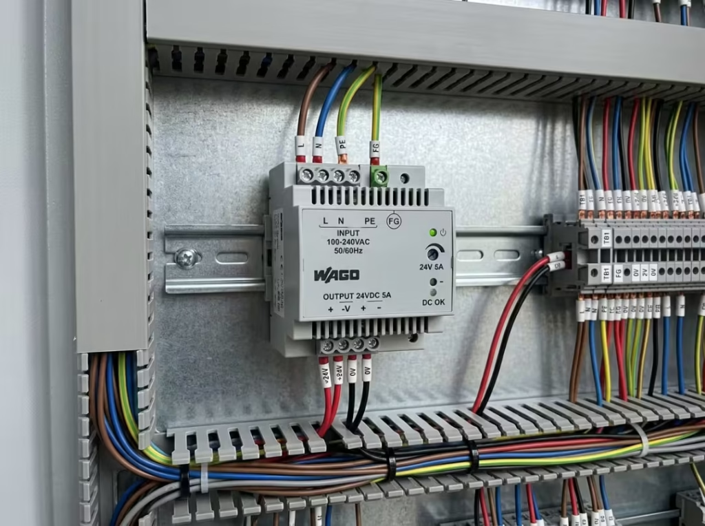
Functional ground (FG) and protective earth (PE) both connect to “ground,” but they serve opposite purposes. FG is a signal reference that reduces noise and improves circuit performance. PE is a safety conductor that protects people when insulation fails. Protection class (I, II, or III) defines the shock-protection method—FG never changes it.
You’re wiring up a 24V DIN rail supply when you spot a terminal marked “FG” and pause. Is that the same as the protective earth screw two terminals over? It isn’t—and treating them as interchangeable is one of the fastest ways to build an installation that’s either noisy, unsafe, or both.
Both terminals involve grounding. But one exists to keep people alive during a fault, and the other exists to keep your circuit running cleanly. By the end of this guide, you’ll be able to read a power supply label, know which terminals protect people, which improve circuit behavior, and how to wire each one correctly in a real system.
Why This Confusion Causes Real Problems
The FG/PE mix-up rarely shows up on a schematic review. It shows up in the field—usually after the panel is built, powered, and behaving strangely.
Here’s the pattern. An engineer sees “ground” on a label and wires every ground-like terminal to the same panel earth bar. On paper it looks tidy. In practice, ground loops form, common-mode noise couples into analog channels, and an ADC that read clean on the bench starts jittering by several LSBs on-site. Nobody suspects the grounding scheme because “everything is grounded.”
The dangerous version runs the other way. Someone assumes an FG terminal provides fault protection, so they skip a proper PE connection on a Class I metal-enclosure supply. The enclosure now looks bonded—there’s a wire on it—but that wire carries only leakage current and can’t clear a fault. If basic insulation breaks down, the chassis goes live, and the breaker never trips. The installation passes a visual check and fails the one test that matters.
Both failures come from the same root cause: assuming “ground is ground.” It isn’t. Getting this distinction right early saves you from chasing phantom EMC problems and, more importantly, from shipping a genuine shock hazard.
Functional Ground vs. Protective Earth: What’s the Difference?
This is the core distinction, so it’s worth stating plainly.
Protective Earth (PE) is a safety conductor. It ties exposed conductive parts—typically a metal enclosure—to building ground. If basic insulation fails and a live conductor touches the chassis, fault current flows down the PE wire, tripping a breaker or blowing a fuse quickly enough to keep the chassis from remaining at a dangerous voltage. PE exists to protect a human being when something goes wrong.
Functional Ground (FG) is a circuit reference. It provides the supply’s internal filter and output circuitry with a low-impedance connection to a reference point, reducing noise and improving immunity. FG does nothing to protect a user during an internal breakdown. It carries small leakage and common-mode currents by design—not fault current.
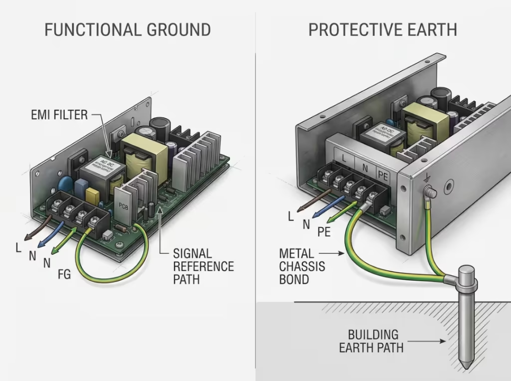
They can absolutely coexist in one unit. A supply may have both an FG terminal and a PE terminal, and in some designs they’re bonded together internally. But coexisting is not the same as being interchangeable. You never substitute one for the other.
Functional Ground (FG) | Protective Earth (PE) | |
|---|---|---|
Purpose | Circuit/signal reference; reduces noise, improves EMC and immunity | Safety; protects people when insulation fails |
Current level | Small leakage and common-mode currents (mA range) | Full fault current until protection trips (can be tens/hundreds of amps) |
Standard requirement | Not a protective conductor; not mandatory for safety | Mandatory for Class I equipment; sized and verified as a safety conductor |
Where it connects | To the 0V/COM of sensitive electronics, or a defined reference point | To the building’s protective earthing system via a grounded outlet or panel bar |
The rule you never break: real electrical safety comes from a genuine PE conductor or from Class II insulation. It never comes from a functional node that exists solely to make the circuit run more cleanly. If someone tells you “the FG is grounded, so it’s safe,” ask whether that FG point is actually earth-bonded and rated as a protective conductor. Usually it isn’t.
What Functional Ground Actually Does in a Power Supply
Functional ground is a low-impedance reference or return path that keeps a circuit operating correctly. That’s the whole job. It is not a shock-protection conductor, and reading it as one causes the safety failures above.
On most AC-DC and DC-DC supplies, the FG terminal sits near the output or on a dedicated terminal block, often marked “FG” or with a ground symbol distinct from the protective earth symbol. Check the datasheet, because marking conventions vary between manufacturers.
FG does three concrete things inside a switching supply:
- Zero-voltage reference for control signals and output circuits, giving downstream electronics a stable 0V to measure against.
- Return path for common-mode current generated at the switching frequency. Every switching supply produces this current; FG gives it a controlled path back instead of letting it wander through your signal wiring.
- Ground reference for the internal input filter that suppresses conducted EMI. Without that reference, the filter can’t do its job properly.
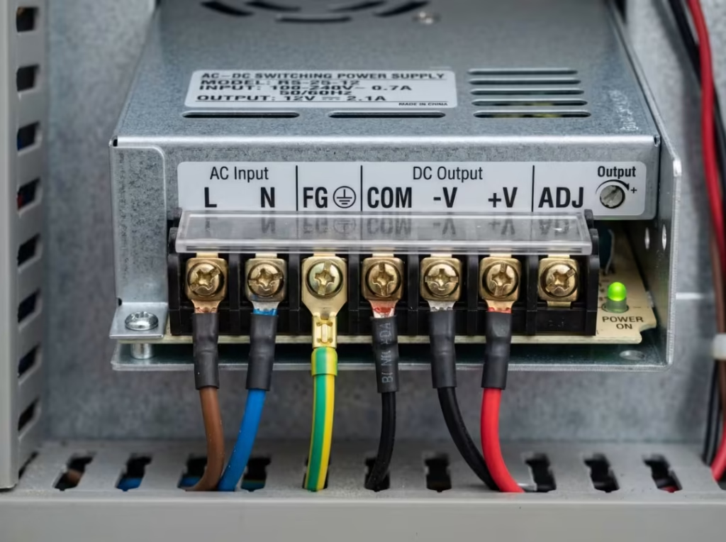
Here’s the nuance that trips people up: the FG carries leakage current from the supply. That’s normal and expected. Because it carries current, ignoring the terminal causes real problems—but under the standard, FG is still not a protective conductor. It handles milliamps of leakage, not the fault current a breaker needs to see.
Leave FG floating, and you invite noise, output drift, and EMC headaches. What you never get from FG—connected or not—is a safety guarantee.
Protection Classes Explained: Class I, II, and III
Protection classes, defined under IEC 61140 and related standards, describe how a power supply prevents a lethal shock when basic insulation fails. The class on the label indicates the protection method, not the quality. A well-built Class II supply and a poorly built Class II supply carry the same class marking—the class describes strategy, not performance.
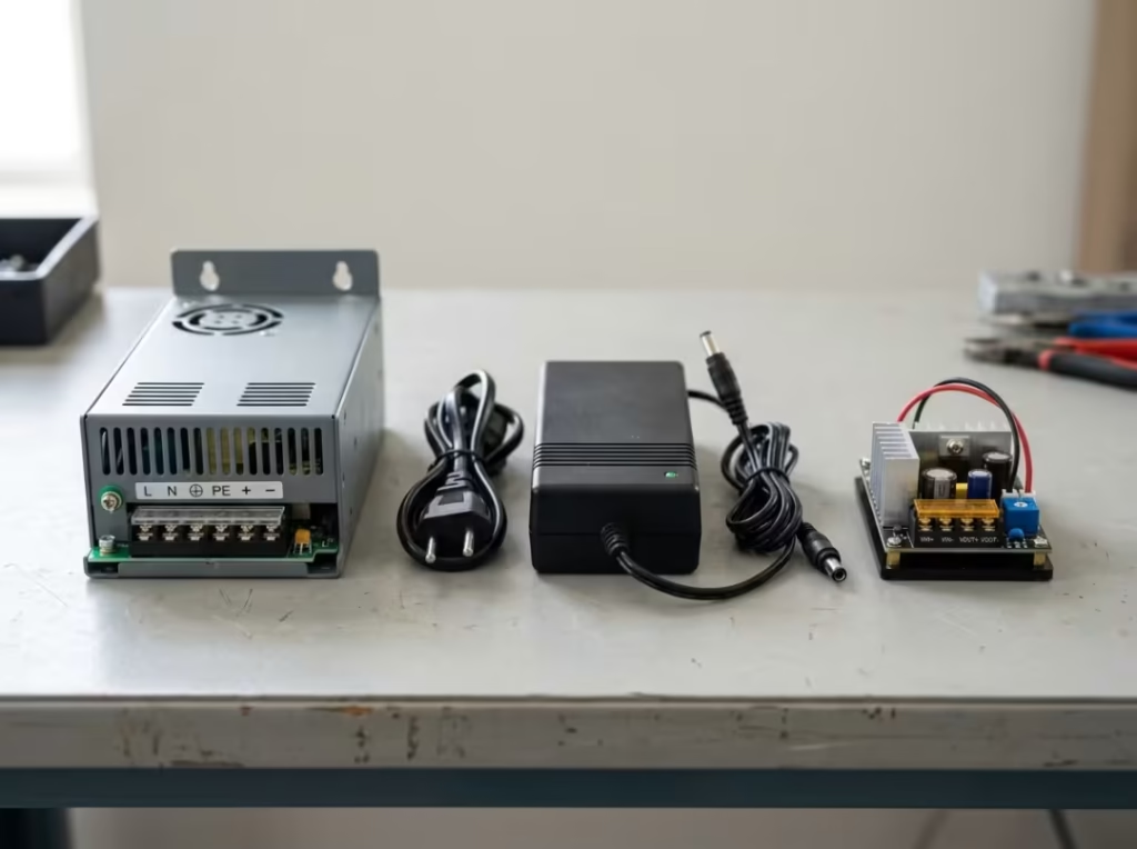
Class I — Protection Through Protective Earth
A Class I supply relies on a conductive enclosure bonded to protective earth. The fault path is the whole point: if basic insulation fails and a live part contacts the metal enclosure, fault current flows down the PE wire, trips the upstream protection, and keeps the exposed metal from sitting at a hazardous voltage.
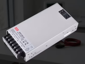
You’ll find Class I in industrial supplies, inside metal enclosures, in server PSUs, and in high-power AC-DC converters bonded to panel ground. These are exactly the units you spec for networking gear and industrial control panels—the kind of certified ITE power supplies built to IEC 62368-1 and installed inside metal chassis with a solid earth path. The non-negotiable requirement: a reliable PE connection and a genuinely grounded outlet or panel bar. Remove the earth and a Class I supply loses its entire protection scheme. There’s no backup layer—the earth is the safety.
Class II — Double or Reinforced Insulation
Class II supplies—often called “no-ground” or safety-insulated—protect the user with insulation rather than earthing. Protection comes from either double insulation (two independent layers) or reinforced insulation (one robust barrier engineered to be equivalent to two) between live parts and anything the user can touch.
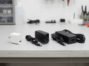
Because safety doesn’t depend on grounding, there’s no PE terminal to connect. Exposed parts remain safe even without earth present. This is why laptop chargers, plastic-enclosure supplies, appliance supplies, and many LED drivers are Class II. It’s also common in medical power supplies, where desktop and wall-mounted adapters for portable and home healthcare devices rely on double insulation rather than a grounded chassis. The real advantage is deployment: Class II shines wherever a reliable earth connection isn’t available at the installation point—for field equipment, portable gear, or older buildings with questionable grounding.
Class III — Powered From SELV
Class III works on entirely different logic. Instead of earthing or heavy insulation, the device is fed from a separated or safety extra-low voltage (SELV) source. The output stays below the hazardous threshold under normal conditions, so the user is inherently protected—there simply isn’t enough voltage present to be dangerous.
Clear up a common confusion here: you rarely see “CLASS III” stamped on a mains-connected supply. The marking usually describes the powered equipment, not the supply feeding it. For example, a 24V sensor module, treated as Class III, sits behind an isolated Class II/SELV supply that provides the actual mains isolation. That upstream supply must still provide proper isolation from the mains, and that responsibility sits squarely with its manufacturer—not with the Class III device downstream.
How Functional Ground and Protection Class Interact in Real Designs
This is where experienced engineers still get tripped up, so it’s the real payoff of understanding the two concepts separately.
Two combinations show up constantly in the field:
A Class II supply with an FG terminal. This surprises people—if it’s Class II and needs no earth, why is there a ground terminal? Because the FG here is an isolated 0V reference for the output, not part of the safety scheme. The supply is safe by insulation. The FG is there purely to give your circuit a clean reference and a path for common-mode current. Connecting it doesn’t make the supply “grounded” in the safety sense, and leaving it off doesn’t make the supply unsafe—it just makes it noisier.
A Class I supply where FG and PE are tied together. In many metal-enclosure Class I designs, the functional ground and protective earth are bonded internally or via the chassis’s mechanical design. Here they physically share a node, which is exactly why engineers assume they’re the same thing everywhere. They’re not—this bonding is a design decision specific to that unit, confirmed in the datasheet, not a universal rule.
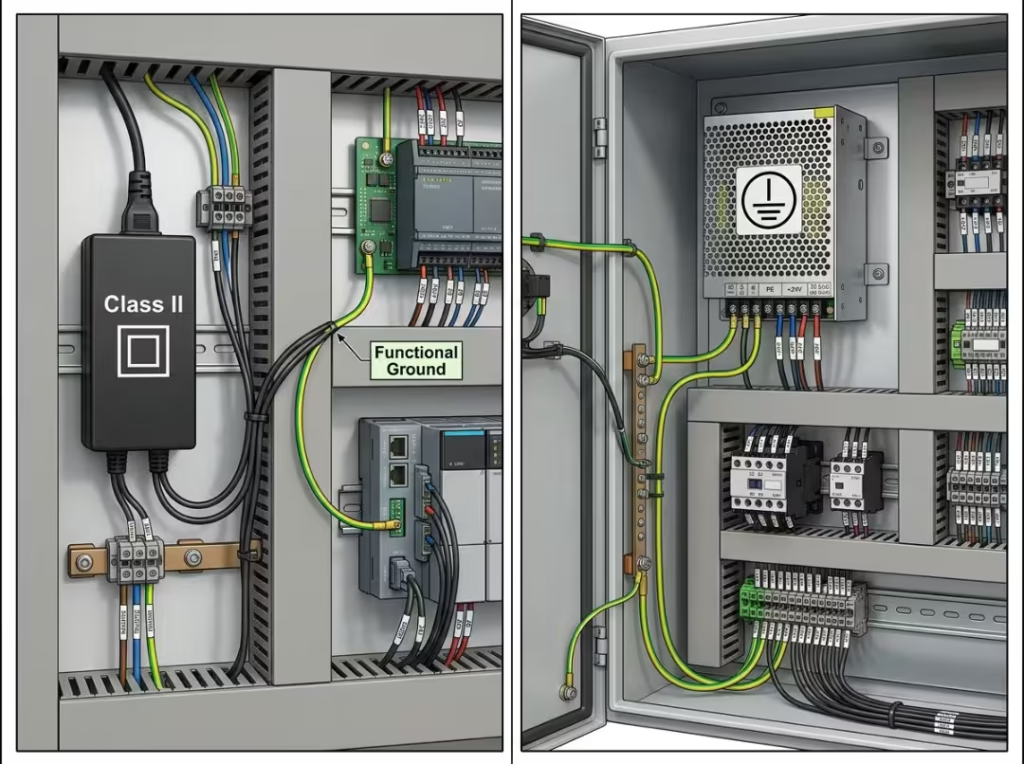
The central point is that FG does not change the protection class. The protection class determines whether the chassis is safe to touch after a fault. FG decides how clean and stable your circuit runs. They’re independent axes. A supply can be Class II with excellent functional grounding, or Class I with poor signal-reference practice on your side of the terminals.
A practical design tip: for a low-noise analog reference or a sensitive control card, route a dedicated functional ground from the supply output to the card’s 0V/COM. Don’t lean on protective earth for signal return—PE carries leakage and potentially fault current, and it’s the last place you want your ADC reference. Getting this separation right on paper, before you strip a single wire, is what keeps a clean design from turning into a field debugging job.
The Most Common Wiring Mistakes
These are the five FG/PE mistakes that cause the most field failures. Each follows the same shape: what people do, what goes wrong, and how to fix it.
Leaving the FG terminal disconnected. The result is raised common-mode noise and, in some designs, an output that floats and drifts. Analog readings wander, and EMC tests fail for no obvious reason. Fix: connect FG exactly as the datasheet intends—usually to the 0V/COM of the load or a defined reference point, not left dangling.
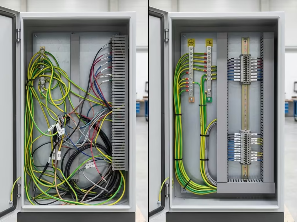
Using PE as a signal ground return. Engineers tie a sensitive circuit’s return to the protective earth bar for convenience. This injects mains-frequency and leakage noise straight into mixed analog/digital systems, and creates ground loops that are miserable to debug. Fix: keep protective earth and signal returns separate. Route a dedicated functional return for sensitive loads.
Relying on FG to clear a fault when it isn’t bonded to PE. Someone wires a metal chassis to an FG terminal and assumes it’s protected. But FG carries only leakage current—it can’t trip a breaker. If insulation fails, the chassis goes live and stays live. This is a genuine shock hazard hiding behind a wire that looks like a safety ground. Fix: never substitute FG for PE. Bond exposed metal to a verified protective earth conductor.
Assuming “Class II” or “two-wire” is always fine while ignoring leakage. A plastic case is safe because of its insulation, so people stop thinking about grounding entirely. But if the design has any exposed metal part, that part may still require FG or PE treatment, and leakage current may still exist. Fix: check the leakage values in the datasheet and confirm the bonding requirements for any accessible conductive parts.
Misreading a Class III rating and assuming every output is always touchable. “Class III means SELV means safe to touch”—so nobody checks the actual voltage. But an output remains within the safe range only if it’s genuinely within SELV limits under all conditions. Fix: verify the actual output voltage against SELV thresholds rather than relying on the class marking alone.
How to Choose and Wire the Right Power Supply
Turn all of this into decisions you can make at your desk today.
Start with the label and the datasheet—before you strip a single wire. Confirm whether the supply is Class I, II, or III, and read exactly what the FG terminal is designed to do. Two supplies with identical output specs can have completely different grounding requirements.
Selection guidance:
- Choose Class I where a metal enclosure is standard and your installation can guarantee a solid, verified earth connection. Industrial panels and rack systems usually fit here.
- Choose Class II for plastic enclosures, portable equipment, or any site where you can’t trust the earth connection. If the building’s grounding is a question mark, Class II removes that risk from your safety scheme entirely.
- Wire FG to the 0V/COM of your sensitive electronics when a control signal needs functional grounding. Never route it to building earth as a shortcut for signal return.
A short installation checklist before you commit to a layout:
- Check the datasheet’s leakage current values against your application limits.
- Connect PE wherever the protection class requires it, using a properly rated conductor.
- Use a separate functional return for sensitive analog or control loads.
- Keep the FG wire visually distinct—use a dedicated terminal block or connector color—so the next engineer doesn’t mistake it for earth.
- Confirm certification against the relevant IEC standard before you rely on the stated class.
That last point matters more than it looks. A protection class is only as trustworthy as the testing behind it. Verifying that a supply’s class and EMC behavior are validated—ideally through documented in-house testing and EMC facilities covering high-voltage insulation and full conducted and radiated emissions—is what turns a label into a claim you can build around.
Class I vs. Class II vs. Class III at a Glance
Use this table when you’re scanning a datasheet and need the essentials fast.
Class | Basic protection method | Needs PE connection? | Typical enclosure | Example uses |
|---|---|---|---|---|
Class I | Protective earth bonds exposed metal; fault current trips protection | Yes — mandatory | Conductive/metal | Server PSUs, industrial supplies, high-power AC-DC converters |
Class II | Double or reinforced insulation; no reliance on earth | No | Plastic/insulated | Laptop chargers, LED drivers, appliance and portable supplies |
Class III | Fed from SELV; output below hazardous voltage | No (device level) | Varies | SELV-fed sensors and control modules behind an isolated supply |
When scanning a datasheet, find the class first—it tells you your safety obligations—then check what the FG terminal does, which tells you your signal-integrity obligations.
Frequently Asked Questions
What is the difference between functional ground and protective earth?
Protective earth is a safety conductor that carries fault current to trip a breaker and protect people. Functional ground is a circuit reference that reduces noise and carries only small leakage current. PE protects users; FG improves performance.
Does the FG terminal need to be connected for the supply to work?
The supply usually powers up with FG floating, but it won’t perform correctly. Expect higher common-mode noise, possible output drift, and EMC failures. Connect FG as specified in the datasheet for stable, clean operation.
Why would a switching power supply have an FG terminal at all?
Switching supplies generate common-mode current and rely on an internal EMI filter that needs a reference. FG provides both—a controlled return path for that current and a reference point for the filter and output circuitry.
Is a Class II power supply “double insulated” for every circuit, including the output?
Class II guarantees double or reinforced insulation between hazardous live parts and the user. It does not automatically mean the output is SELV or touchable. Check the output voltage and isolation spec separately.
Can a Class I power supply be used in a cabinet without a grounded metal frame?
Not safely. Class I depends entirely on a reliable protective earth connection. Without a verified earth path, a fault can leave the enclosure live, and the breaker won’t trip. Either guarantee the earth or choose a Class II supply.
Why does my control circuit read about 50V AC when it’s fed from a supply with a floating output?
That’s leakage current through the EMC filter’s Y-capacitors driving a floating output to roughly half the line voltage. It’s high-impedance and typically harmless, but it disappears once you connect FG to a proper reference—confirming FG was never wired.
The Bottom Line
Protection class and functional ground answer two different questions. Protection class—I, II, or III—decides whether a person stays safe after an internal fault. Functional ground ties a circuit’s reference to a clean, low-voltage point to reduce noise and stabilize your signals. One protects people; the other protects performance.
The non-negotiable rule: FG must never replace PE unless the manufacturer confirms the FG point is earth-bonded and the protection class allows it. Before you commit a PCB or panel layout, check the label, read the datasheet, and draw your grounding topology on paper. Sorting FG from PE at the design stage costs minutes. Sorting it out after a failure costs far more.