A product runs flawlessly on your bench for months, then fails radiated emissions on its first scan at an accredited lab. Now the ship date slips, the board needs a respin, and the root cause traces to a decision made six months ago. EMC belongs in your first schematic review, not in a certification checkbox at the end. This article covers how EMI and EMC differ, why failures surface so late, and the low-cost habits that pull testing into your design flow.
EMI vs. EMC: The Distinction That Costs You a Respin
EMI Is the Disturbance; EMC Is the System Property
EMC is a system property, not a component spec. EMI is the unwanted electromagnetic energy itself; EMC is your device’s ability to work inside its environment without disrupting anything around it.
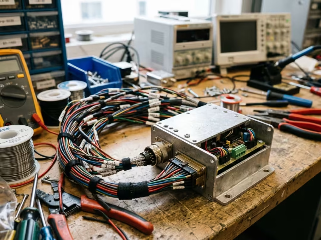
Buy fully compliant parts, yet still ship a non-compliant product. A well-shielded module sails through its own qualification, then radiates like an antenna once it’s wired in — because nobody accounted for the return path of the current running down its cable harness. The parts were fine. The system wasn’t. Stop grading individual components as “good” and audit the system-level current paths before you trust a single datasheet.
Why a Working Prototype Still Fails Compliance
“It works” and “it passes” are independent results. Never infer one from the other.
Functional testing rewards a clean, controlled bench. Compliance testing subjects your device to a standardized, deliberately harsh setup designed to find weaknesses. A device streams video perfectly at your desk, then resets mid-sweep during radiated immunity because a reset line has no filtering and picks up the injected field. Filter the vulnerable lines before you assume the prototype is safe.
The Four Test Areas That Decide Your EMC Result
EMC is four problems, not one. Frame each by the question it answers:
- Radiated emissions — how much noise does the device broadcast through the air?
- Conducted emissions — how much noise does it push back onto the power line?
- Radiated immunity — can it survive external fields without malfunctioning?
- Conducted immunity — can it tolerate disturbances arriving through its cables and ports?
Most teams chase emissions and ignore immunity — until units start crashing in the field and a customer’s Wi-Fi router or a nearby motor turns out to be the trigger. A field crash costs far more than a bench measurement, so build an immunity check into every prototype review.
Why EMI/EMC Problems Surface Too Late
Your Bench Is Too Clean to Trust
A confident bench result is not evidence of compliance — it hides the failure modes that matter most. Short cables, no realistic loads, ideal grounding, and a quiet RF environment mask the exact problems a standardized setup exposes.
The setup is part of the measurement. Change any of these, and your numbers move:
- Cable length and routing
- Table height above the ground plane
- Ground plane presence
- Enclosure state — open on your desk versus closed in the chamber
- Ambient temperature and humidity
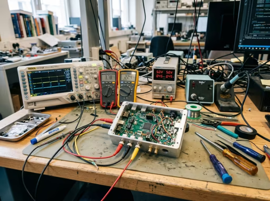
A device clears its limits at 23°C in your office, then drifts out of spec in a warmer, higher-humidity chamber. The physics didn’t change; your bench never reproduced the conditions that get measured. Reproduce the chamber’s cabling, grounding, and enclosure state on your own desk before you make any claim about compliance.
Most Failures Trace Back to Early Design Decisions
A lab failure is almost never a lab problem. It’s a decision made months earlier, surfacing at the worst possible moment — and by the time the chamber reports it, the cheap window to fix it has closed. Here are the usual culprits, each with its cause, physical effect, and lab symptom.
- Return paths. Route a high-speed signal over a split plane, and its return current detours around the gap. The detour increases the loop area, which drives up radiation and crosstalk. In the chamber, it reads as a specific harmonic spiking above the limit, and the fix means moving copper. Keep a solid reference under every fast edge and audit plane splits at layout review.
- Clock and switching-regulator routing. A high-dV/dt or high-dI/dt node near I/O or a board edge becomes an efficient, unintentional antenna. The result is broadband emissions climbing across a wide span — far harder to chase than a single tone. Pull those nodes into the board interior and keep their loops tight before you route anything else.
- Connector and cable placement. These get locked early for mechanical reasons, then dominate radiated emissions because the harness carries noise straight out of the enclosure. Fight for connector positions at the mechanical review, not after tooling.
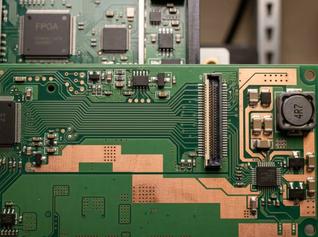
The one that stings most: an immunity failure traced to a connector location frozen into the enclosure six weeks earlier. Mechanical locked it, tooling followed, and the only real fix is a respin plus a slipped schedule. Flag every one of these decisions at the design review, before any copper or plastic is committed. That’s the only stage where they’re cheap to change.
A Pass at the Limit Is a Fragile Pass
Stop celebrating a 1 dB win. A result sitting on the limit line is fragile, not safe — compliance limits are a legal minimum, not a promise of field robustness. A device can meet radiated immunity limits and still crash the moment a specific transmitter sits beside it.
You test one sample and ship thousands. Component tolerances, layout variation, and cable routing shift unit to unit, so a marginal sample guarantees a batch that fails. A first article that passes by 1 dB looks fine until a later run fails because a capacitor supplier changed and moved a resonance you were sitting on top of. Treat the limit as the floor, read the dB number, and design toward real headroom.
What Compliance Requires — and What It Doesn’t Guarantee
Compliance Is a Legal Gate, Not a Badge
In most countries, meeting emissions and immunity requirements is a legal precondition for selling. No compliant report means no legal path to market, so confirm your obligations before you commit to a launch date.
The FCC is the clearest U.S. reference: the rules apply before you market or sell, and enforcement is real. Category sets the difficulty. An intentional radiator, such as a Wi-Fi module, faces a tougher regime than an unintentional radiator, such as a thermostat or a blender. Pin down your category early — it decides what you’ll have to prove and how much test time you’ll buy.
Standards Vary by Product and Market
Identify your applicable standard and class early, before you design toward the wrong limit. International bodies publish the test methods and limit lines that national regulations reference, and the underlying logic is shared even when the labels differ.
A quick map, no tour:
- CISPR 11 and CISPR 32 — commercial and industrial equipment
- ISO 11452 — automotive components
- DO-160 — airborne equipment
- CE marking — the gate for the EU market
The split that catches people is Class A (industrial) versus Class B (residential). Class B is stricter. The same device passes comfortably in an industrial setting and fails outright when aimed at a home. Confirm your class before you set a single design target, or you’ll aim the whole effort at the wrong number and pay for it in redesign.
A Certificate Proves Eligibility, Not Field Robustness
Passing means you met defined requirements under defined conditions — nothing more. The certificate is a starting line for field quality, not a finish line.
Take two products with identical certificates. One clears its limits by 8 dB; the other scrapes through by 0.5 dB. Same paperwork, opposite field behavior. The first absorbs production variation and a noisy environment without complaint; the second generates warranty returns you can’t explain. Read the margin, not just the verdict, and send a hairline pass back before it ships.
Pre-Compliance Testing: Catch Problems Before the Chamber
What Pre-Compliance Testing Actually Does
Pre-compliance is a design tool, not a substitute for the accredited report you need for legal sale. Treat it as one, and it will burn you.
Its jobs are practical: locate your worst-case frequencies, find hot spots on the board, and identify the worst operating mode before you ever book chamber time. Pre-scan well and you walk into the lab already knowing where the risk lives, instead of paying premium hourly rates to discover it. The error runs both ways — over-trust pre-compliance and you assume a legal pass you don’t have; dismiss it for its lower accuracy, and you miss cheap-to-catch problems. Use it for direction: is this design trending toward a pass or a problem? Then confirm at the lab.
Build a Pre-Compliance Bench Without Budget Approval
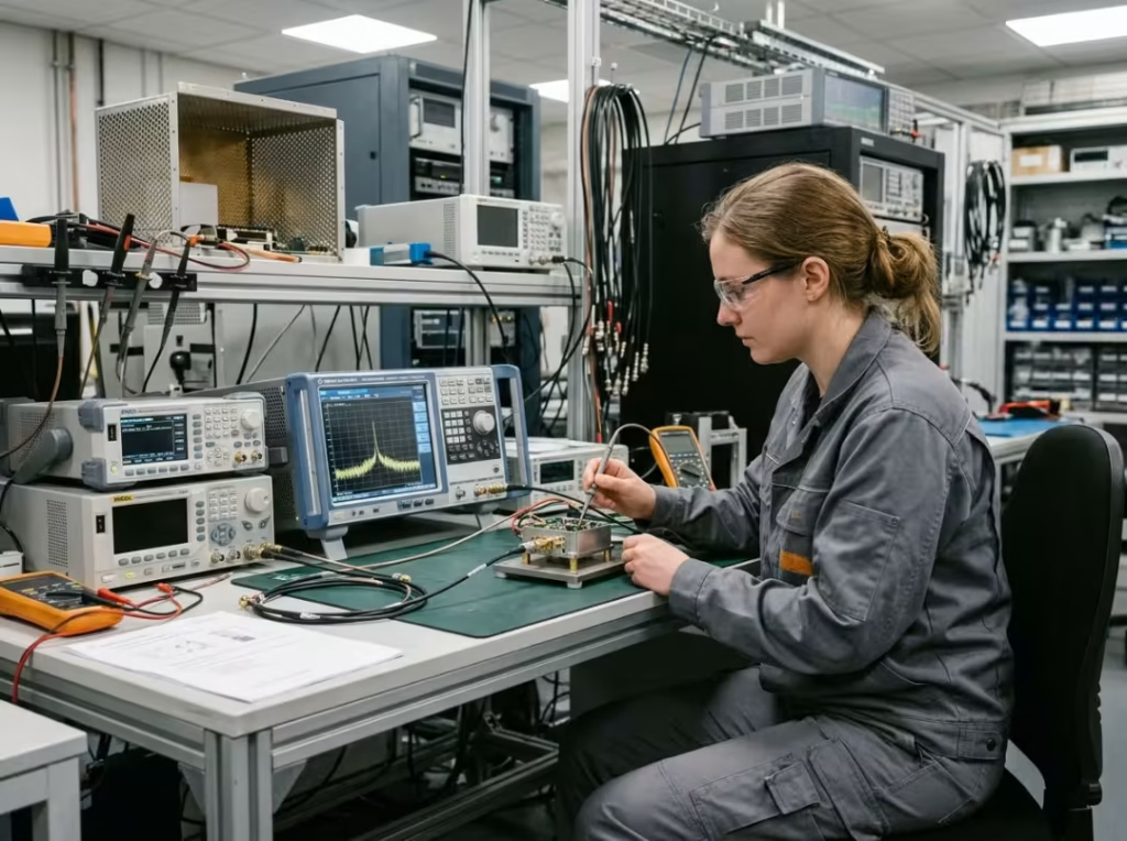
You don’t need a chamber to know you’re heading for trouble. The core kit:
- A near-field probe set — tells you where on the board the noise starts
- A spectrum analyzer (a used one is fine) — tells you which frequencies are hot and how they move as configurations change
- A basic fixture for injecting and measuring signals
- A LISN for conducted-emissions work
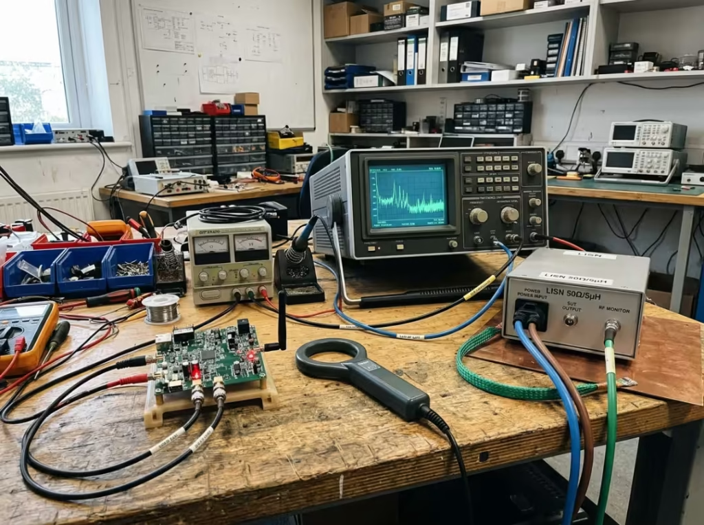
Each tool answers one question, and together they cover most of the obvious risks. Sweep a near-field probe slowly across a running board and watch one clock harmonic light up over a specific trace — you’ve localized the culprit before layout was ever frozen. See the peak, know where it comes from, and move the trace while it’s still free to move.
Why Pre-Scans Save More Than Lab Fees
The real savings aren’t the hourly chamber rate. They’re the respins you avoid, the schedule slips you never take, the repeat lab visits you don’t book, and the cross-team firefighting that never starts. Pre-compliance pays for itself the first time it prevents a single respin.
Put the same defect on two paths. A ground loop found at your desk with a ~$100 probe and a used analyzer is an afternoon of tracing and a filtering tweak. The identical ground loop found at the lab triggers a six-week delay and a respin because it now sits on the critical path, with tooling and launch dates stacked behind it. Same defect, two orders of magnitude apart in cost.
Or take a drone that loses its camera feed the instant the motor controller spins up. Caught early in a bench pre-scan, it’s a filtering and routing tweak. Caught near ship date, it’s a redesign under pressure. Build the pre-scan into the schedule so no one has to argue for it later.
How to Build EMI/EMC Into Your Design Workflow
Schematic Stage: Define Risk Early
The cheapest EMC fixes happen in schematic review, before a single via is placed. Once copper is committed, your options shrink, and your costs climb. Run these checks at the review:
- Power supply topology — where noise gets generated in the first place
- Grounding and partitioning strategy — how you separate noisy and quiet domains
- Interface protection concept — filtering and transient protection at every port
- Decoupling — enough of it, in the right places
- Vendor EMC application notes — check your part choices against them before you commit
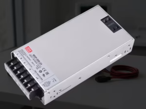
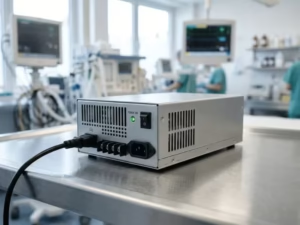
Here’s the trade this stage unlocks: pick a switching regulator with a slower, controlled edge rate over a marginally more efficient one, specifically to avoid a known downstream emissions headache. That’s a five-second decision at the schematic and a multi-week fix if you defer it. Write the reasoning into the review notes so no one “optimizes” it back out later. For applications where the power supply itself is a major EMC variable — medical devices and ITE equipment are two common examples — choosing a supply with built-in EMC filtering and verified pre-compliance data can eliminate an entire category of early-stage risk.
Layout Stage: Win the Emissions Battle Here
Most emissions battles are won or lost in layout, not in a shielding can bolted on at the end. Return-path discipline and node containment beat add-on fixes every time. Work these habits deliberately:
- Keep return paths continuous under high-speed signals. A split plane under a clock is a classic failure seed — route the clock off the split and hold a solid reference beneath it.
- Place decoupling tight to the pins it serves. Loop inductance kills decoupling faster than a wrong capacitor value ever will.
- Keep switching nodes compact and away from I/O. A sprawling switch node near a connector couples noise straight onto cables headed out of the box.
- Route connectors and cables with radiation in mind. The harness is usually your loudest antenna; don’t hand it noise to broadcast.
Reroute a clock trace off a plane split, re-run the pre-scan, and you’ll commonly watch that harmonic drop several dB. Change the layout, measure the result, keep what works. Shielding added later can’t undo a broken reference plane — fix the plane before you reach for a can.
Prototype Stage: Scan Before the Design Is “Finished”
Run a radiated emissions scan on the first prototype, before firmware is mature and before anyone defends a “done” board. Early, imperfect data beats late, perfect data, because the point is to steer while changes are still cheap.
A first-article scan often surfaces an unexpected peak that turns out to be a poorly terminated debug header acting as an antenna. At the prototype stage, that’s a five-minute fix. Discover it after design freeze, and it’s a change request, a review board, and a schedule conversation. Scan early, scan often, and don’t wait for a complete product before starting to measure.
Pre-Lab Prep: Turn Chamber Hours Into Answers
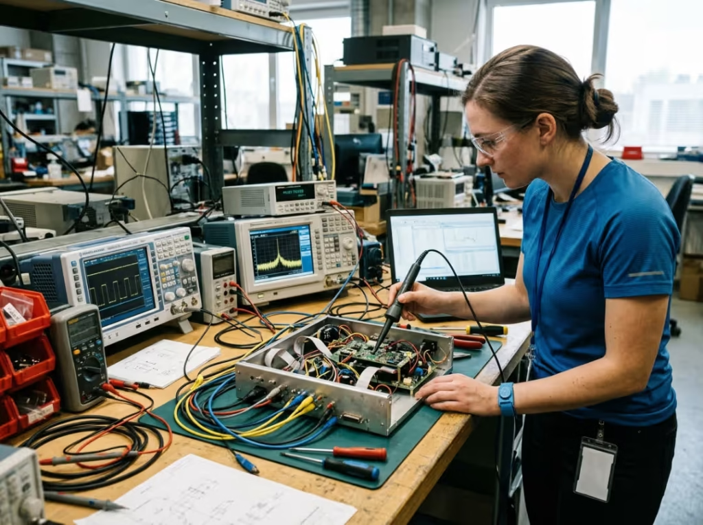
Chamber time is expensive by the hour, so every problem you localize before you arrive saves money and calendar. Before you book time, have these ready:
- A test plan listing the applicable standards, your class or limit, and any special configurations
- The worst-case operating mode identified and ready to run — many labs run a pre-scan to find the worst frequency before the full sweep
- Documentation — the manual, schematics, and a known-issues list so the on-site engineer helps you interpret results, not just run the machine
- A running test log — date, build revision, firmware version, configuration, and result for every scan
That log is your fastest route to a fix. When a result comes back marginal, the first question is always “what changed since the last good scan?” A team that walks in with a documented worst-case mode and a clean change log clears a borderline result in one session instead of booking a second visit.
Where Teams Underestimate EMC Risk
“It Passed on My Bench”
The bench is not the lab, and neither is the field. Cable length, grounding, enclosure state, even the height of your test table — all of it is part of the measurement, and changing any one moves the result. Reproduce the conditions that will actually be measured before you promise anyone a pass. Otherwise, a “guaranteed” bench result becomes a chamber failure you didn’t budget for.
“We Only Need to Pass Once”
A single passing sample tells you nothing about manufacturing variation across thousands of units. Aim for roughly 6 dB below the limit line to account for component tolerances, layout variations, and unit-to-unit differences. Skip the margin and “we passed” becomes a claim your production line can quietly break — a first article clears the bar, then a batch fails after a supplier change nudges a resonance. Set that 6 dB as your internal target from the start.
“We’ll Fix It in Firmware”
Firmware can cut symptoms — spread-spectrum clocking smears a peak, adjusted timing shifts an offender. But when the root cause lives in layout, grounding, or structure, firmware only masks it. A tweak that shaves a peak just under the limit is a fragile pass that a temperature swing or unit-to-unit variation quietly undoes. Firmware is a mitigation, not a patch for physics — reserve it for shaving margin you’ve already earned.
When to Use a Test Lab — and How to Get More From It
What the Lab Should Confirm
The lab’s job is confirmation, not discovery. It produces the official compliance verdict, pinpoints your worst-case frequencies, quantifies your margin, and lets you observe failure modes under controlled conditions. If the chamber is turning up basic issues, your bench didn’t do its job, and you’re paying premium rates to learn what a probe would have told you for free. Teams whose power supply partners operate an in-house EMC lab can often resolve many of these issues before they ever reach an accredited facility.
How to Avoid Wasting a Lab Session
The value of a lab session is set before you arrive. Treat this as a pre-flight checklist:
- Confirm the exact standards and class you’re testing against
- Define your test configurations in advance
- Bring complete documentation — manual, schematics, known-issues list
- Communicate your known risks and target margins up front
- Ask whether they’ll run a pre-scan to find the worst-case frequency before the full run
Two teams book the same chamber hours. The prepared one leaves with a report and a fix; the unprepared one leaves with more questions and a second booking. Do the prep, or plan to pay for the return trip.
Why Prepared Teams Get Better Lab Results
The on-site engineer interprets results far faster when you hand over schematics, the manual, and a list of what you already suspect. That turns the session from a blind hunt into a focused confirmation. Every issue you localized in advance is money and calendar you don’t spend in the chamber. Treat every pre-scan as an investment in cheaper lab time.
Common Questions Engineers Ask Before EMC Testing
Can firmware fix an EMC failure, or only reduce its symptoms?
Sometimes firmware helps — spread-spectrum clocking and timing changes pull a peak down. But if the root cause is layout, grounding, or shielding, firmware only masks it. The decision rule: if the fix depends on a specific temperature, unit, or configuration to stay under the limit, it’s a symptom patch, not a cure. Fix the hardware.
How much margin below the limit line is safe for production?
Aim for around 6 dB below the limit. That headroom covers component tolerances, layout variation, and unit-to-unit differences you can’t see in a single sample. Your one test unit is not your million-unit reality.
Do minor component changes require retesting?
A truly identical form-fit-function swap often doesn’t. Any change that touches clocks, power, filtering, or grounding usually does. Parts with “identical” datasheets can still behave differently in the real circuit, so verify with a quick pre-scan before you assume you’re safe.
How long does a typical pre-compliance session take?
A focused in-house pre-scan runs a few hours. Delays come from unstable test modes, poor fixturing, and unclear worst-case configurations — not from the scanning itself. Good documentation and a defined worst-case operating mode are your biggest time-savers.
Start on Your Next Prototype
Pick your applicable standard and class today. Build a probe-and-analyzer pre-compliance bench and sweep your first board before the layout is frozen. Identify risks in the schematic, control them in the layout, pre-scan the prototype, prepare your worst-case modes, and let the lab confirm rather than discover.
The cheapest EMC fix is always the one you make before the copper is committed. Make it there.