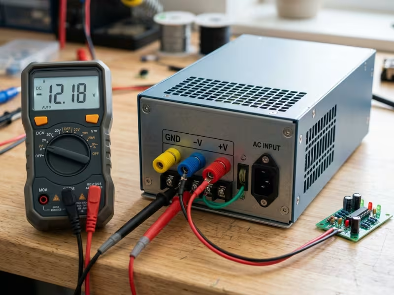
Picture a motor kicking on in your system. The bus voltage dips hard for a moment. Suddenly your sensor readings drift, your MCU resets itself, and the analog front end starts picking up extra noise.
I’ve watched this exact chain of events frustrate engineers on the bench and in the field.
Here’s the thing: unstable voltage isn’t just “slightly worse performance.” It triggers misfires, random restarts, and measurement errors. Over time, it quietly shortens the life of your components.
That’s why a regulated power supply earns its place. Its whole job is to hold the output steady, even when the input fluctuates or the load jumps around.
In this guide, I’ll walk you through three things: what a regulated power supply actually is, how it keeps output stable, and how to choose the right one for real projects.
What Is a Regulated Power Supply?
A regulated power supply keeps its output steady, even when conditions around it shift. Feed it a swinging input voltage, hit it with a jumping load current, or let the temperature climb — it still holds the output inside a specified range.
That word “regulated” trips people up. It doesn’t mean the output never moves at all. It means the supply keeps things within an acceptable tolerance, say ±1% or ±2%, depending on the design. The output can wobble a little. It just won’t drift somewhere it shouldn’t.
Most of the time, we’re talking about voltage regulation — the supply locks onto a target voltage and defends it. But many models can also switch into constant-current mode, capping the current once the load tries to pull too much. That helps with charging or protecting sensitive parts.
One quick note before you go shopping. A regulated power supply is the complete unit that takes raw input and delivers clean, controlled output. A voltage regulator is just the control component inside that does the correcting. A bench power supply is a lab-style box with adjustable knobs and readouts — and yes, it’s usually regulated too.
Now let’s look at what changes when it isn’t.
Regulated vs. Unregulated Power Supply: What Changes in Real Use
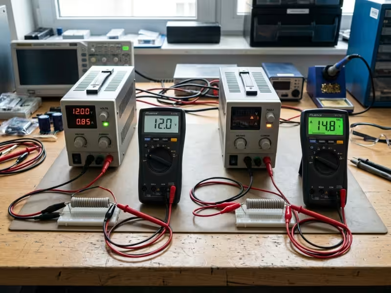
Here’s the core difference. An unregulated supply just passes power through with basic filtering, so its output drifts as your input voltage swings or your load pulls more current. A regulated supply fights back. It runs a control loop that watches the output and corrects it in real time, holding the target voltage no matter what the load or input throws at it.
Dimension | Regulated | Unregulated |
|---|---|---|
Output stability | Tight, stays on target | Drifts with input and load |
Load change response | Fast, holds steady | Sags under heavy load |
Ripple/noise control | Much cleaner | Higher ripple |
Circuit complexity | Higher | Lower |
Cost | Higher | Lower |
Typical applications | Electronics, control, instruments | Simple loads, tolerant devices |
Let me give you a real example that makes this click. Take a 12V unregulated supply. With nothing connected, put a meter on it and you might read 14V or even 15V — noticeably above its nominal rating. Then load it up to full current, and watch that same output sag down to 10V or lower. That’s a swing of several volts, purely from the load changing. A regulated 12V supply holds close to 12V through both extremes.
So do you actually need regulated? Ask yourself one thing: does your device care about a stable, clean rail? If you run microcontrollers, sensors, analog circuits, or anything that measures or communicates, the answer is yes. If you drive a simple heater, a basic motor, or a rugged load that shrugs off voltage swings, an unregulated supply saves you money and does the job fine.
How a Regulated Power Supply Works
So what actually happens inside the box that lets it hold a steady output? Let me walk you through it the way I’d explain it at a workbench — no textbook detours.
From AC to Stable DC
The power moves through a chain of stages. Each one does a specific job.
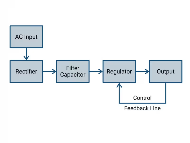
First, the input arrives. That might be AC from the wall or DC from a battery or bus. Next comes rectification, which turns AC into rough DC. Then filtering smooths out the biggest bumps. After that, regulation steps in to lock the output onto a target. And finally, feedback correction keeps checking the result and nudging it back on track.
Think of it as a relay. Each stage hands off cleaner power to the next.
The Core Idea: Feedback
This is where the real magic lives. Everything else just sets the stage for this one trick.
The supply never stops watching its own output. It samples the actual voltage, then compares that reading against the target you set. If the output creeps too high, the circuit pulls it down. If it drops too low, the circuit pushes it back up.
That loop runs constantly, thousands or millions of times a second.
So when your load suddenly demands more current, or your input voltage sags, the output tries to move — and the feedback loop catches it and corrects it almost instantly. That’s why the rail stays put while everything around it shifts.
Why Filtering Alone Isn’t Enough
Here’s a mistake I see all the time. People assume a big filter capacitor solves everything. It doesn’t.
Capacitors do help. They knock down ripple and smooth the rough DC coming out of rectification. But a capacitor can’t think. It has no idea what your target voltage is, and it can’t respond when the load jumps or the input drifts.
Filtering cleans the signal. Feedback controls it. You need both.
Only the control loop actively fights back against real-world changes. That’s the part doing the heavy lifting. And how that loop gets built matters a lot, which leads us straight into linear versus switching supplies.
Linear vs. Switching Regulated Power Supplies
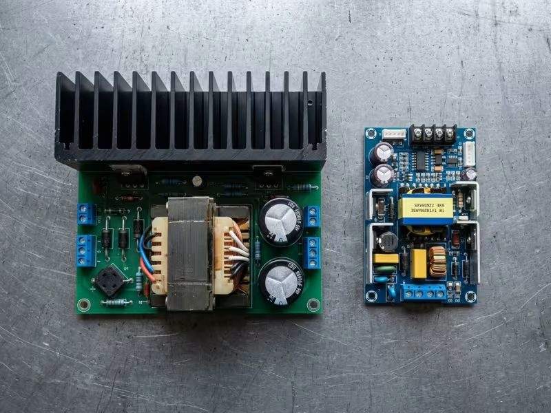
By now you might picture “regulated” as one thing. It isn’t. Both linear and switching supplies are fully regulated — they both hold your output steady. What separates them is how they do it. A linear supply burns off the extra voltage as heat, correcting smoothly and continuously. A switching supply chops the power on and off at high speed, then filters the result. Same goal, very different path.
Factor | Linear | Switching |
|---|---|---|
Efficiency | Lower | Higher |
Noise | Lower | Higher |
Heat | More | Less |
Size | Larger | Smaller |
EMI concerns | Minimal | More important |
Best for | Sensitive analog, low-noise rails | High power, compact, efficient systems |
Now let me clear up three things I hear engineers get wrong.
First, don’t crown linear as “the better one.” It isn’t better across the board — it’s just quieter. That low-noise output makes it a favorite for precision analog, sensitive measurement gear, and clean reference rails. But it wastes energy and runs hot. Try to power a big load with a linear supply and you’ll fight a heat problem you didn’t need.
Second, don’t write off switching as “the noisy one you should avoid.” Plenty of real systems can’t function without it. When you need high power, tight space, or serious efficiency, switching wins easily. Your laptop charger, your industrial DC bus, your compact embedded board — they all lean on switching for a reason. The extra noise and EMI stay manageable with good layout, shielding, and filtering.
Third — and this is where seasoned designers land — you don’t always have to pick a side. Hybrid designs are everywhere, and for good reason. A common trick puts a switching stage up front to handle the heavy lifting efficiently, then follows it with an LDO to scrub off the remaining noise before it reaches sensitive circuits. You get the efficiency of switching and the clean rail of linear, stacked together.
So the real question isn’t “which type is superior.” It’s “what does this specific rail need to do?” Answer that, and the choice usually makes itself.
Which Specs Actually Matter When Choosing a Regulated Power Supply
A datasheet throws dozens of numbers at you. Most don’t decide whether the supply works in your project. A handful do. Let me show you the ones I actually check before I trust a supply with a real load.
Spec | What it tells you | Why it matters in practice |
|---|---|---|
Output voltage and current rating | The target voltage and the max current it can deliver | Sets the baseline — undersize this and the supply sags or shuts down |
Load regulation | How much output shifts as the load changes | A weak number means your rail moves every time current jumps |
Line regulation | How much output shifts when input voltage swings | Tells you if a shaky mains or bus will follow through to your load |
Ripple and noise | The AC junk riding on top of your DC | Wrecks ADC readings, sensors, RF, and precision analog if too high |
Efficiency | How much input power reaches the load | Low efficiency means wasted energy — and heat you have to deal with |
Thermal performance / derating | How much output you lose as temperature climbs | A supply rated at 25°C may deliver far less in a hot cabinet |
Protection features | Response to short, overcurrent, overvoltage, overtemp | Decides whether a fault trips safely or takes your board with it |
Isolation / safety compliance | Barrier between input and output, plus certifications | Matters for safety, leakage, and passing audits or approvals |
Mechanical fit and cooling | Size, mounting, connectors, airflow needs | A perfect spec sheet means nothing if it won’t fit or breathe |
Read that table with your own load in mind. Ripple tells you if your measurements stay clean. Load regulation tells you if the rail holds when current spikes. Thermal performance tells you if the supply survives a sealed enclosure in summer. Protection tells you what happens on the worst day, not the best one.
Mistakes I See Over and Over
Even sharp engineers trip on the same four things. Watch for these.
Checking only rated voltage and current. You match 12V and 5A, feel done, and never look at ripple. Then your sensor readings drift and you spend a week chasing a ghost that lived in the power rail all along.
Leaving no current headroom. You size the supply to the exact peak draw. The first inrush surge or dynamic load spike pushes past that limit, and the output collapses. Give yourself room — I aim for 20 to 30 percent above worst-case.
Chasing efficiency and ignoring heat. A high-efficiency number looks great on paper. But if you never plan the thermal path, that small loss still cooks the parts around it. Treat efficiency and cooling as one decision, not two.
Testing only on the bench. Lab conditions lie to you. Room temperature, clean input, no vibration — everything behaves. Ship it into a hot, shaking, brownout-prone site and the story changes fast. Test against the real environment before you commit.
Nail these specs and dodge these traps, and you’ve already done most of the hard work.
How to Choose One: A Practical Selection Process
Specs matter, but a good choice comes from a repeatable process. Here’s the exact order I work through when I pick a supply for a real project. Skip a step and you pay for it later.
Step 1: Define the load first. Start with what your circuit actually needs, not what a supply offers. Write down your output voltage, your continuous current, and your peak current. Then note how much ripple your load tolerates. And don’t forget startup — motors, capacitors, and some processors pull a big inrush spike at power-on, or swing hard during operation. Size for that spike, not the average.
Step 2: Understand the input side. Look at where your power comes from — mains, a battery, or a DC bus. Each behaves differently. Find the worst-case input range, not the nominal number. Ask what happens during a brownout, a surge, or a fast transient. A supply that copes with 90V mains dips saves you a field failure.
Step 3: Decide between linear and switching. Now match the technology to the job. Sensitive analog or RF? Lean linear for the quiet output. Need high power, small size, or strong efficiency? Switching wins. Weigh your thermal space, your budget, and your size limits together — they usually point to one answer.
Step 4: Leave real margin. This is where people cut corners and regret it. Give yourself 20 to 30 percent power headroom above worst-case draw. Check the temperature rise inside your enclosure, not on the open bench. And never plan to run a supply at full load around the clock — that shortens its life and steals your safety net.
Step 5: Check protection and compliance. Confirm the supply defends itself. Look for overcurrent, overvoltage, overtemperature, and short-circuit protection. Then match the certifications your industry demands. A missing approval can stall an entire product launch. When a standard part doesn’t fit your voltage, connector, or footprint, custom power adapters let you spec the exact ratings and protections your design needs.
Step 6: Verify the install reality. A perfect supply that won’t fit is useless. Measure the physical size, the connectors, the mounting style, and the airflow it needs. Check your wiring length too — long runs drop voltage and add noise.
Keep this checklist handy and run it every time:
- Load defined: voltage, continuous + peak current, ripple limit, inrush
- Input mapped: source, worst-case range, brownout/surge behavior
- Linear vs. switching chosen for noise, efficiency, heat, size, cost
- 20–30% power and thermal margin built in
- Protection features and certifications confirmed
- Fit checked: size, connectors, airflow, mounting, wiring length
Where Regulated Power Supplies Matter Most
Some loads shrug off a shaky rail. Others fall apart. Here are four places where I never cut corners on regulation.
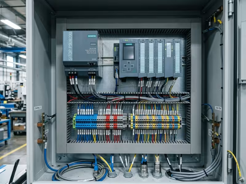
Industrial control and automation. Factory floors run noisy, electrically speaking. Motors switch, contactors slam, and every one of them dumps interference back onto your 24V control bus. Your PLC, sensors, and actuators all share that rail. If it sags or picks up noise, a sensor sends a bad reading, an actuator misfires, or the PLC logs a fault that never really happened. A regulated supply holds the 24V steady through all that switching chaos, so your control system trusts what it sees.
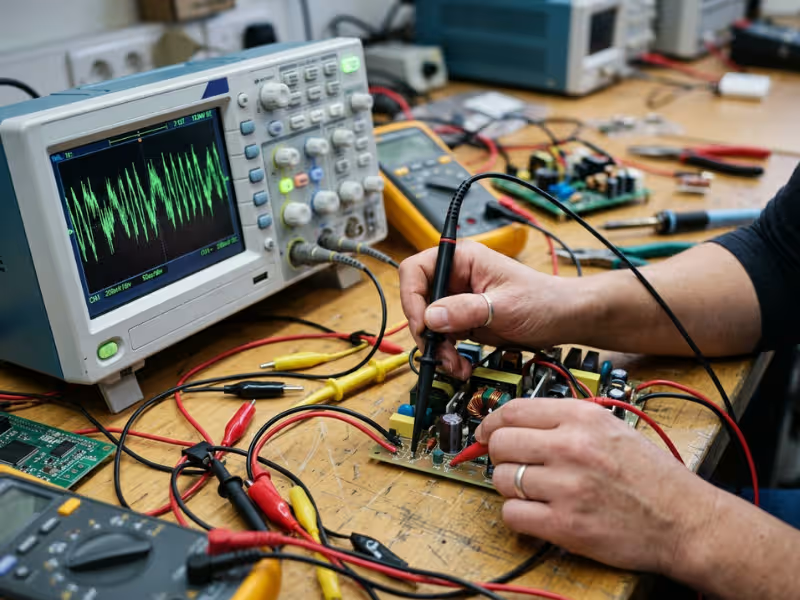
Test and measurement. Here, your power supply is part of the instrument. Ripple and noise on the rail leak straight into your readings. A few millivolts of junk can swamp the signal you’re trying to measure, and suddenly your calibration drifts and your data lies to you. When accuracy is the whole point, you need a clean, stable output that adds no error of its own.
Medical and sensitive electronics. Reliability isn’t a nice-to-have here — it’s the requirement. These devices need stable rails, strong isolation, and very low leakage current for patient safety. A regulated supply keeps the output predictable and the isolation barrier intact, so the equipment behaves the same way every single time. There’s no room for a rail that wanders, which is exactly why purpose-built medical power supplies carry tighter leakage and isolation ratings than general-purpose units.
Embedded and communication equipment. Processors, RF modules, and network gear draw bursty, transient loads. One moment a chip idles; the next it fires up a radio or a core and yanks current hard. An unstable rail dips during those bursts, and that’s when you get resets, dropped packets, and link errors. Matching an ITE power supply that snaps back fast keeps the processor from ever noticing the demand spike.
The pattern is simple. The more your device measures, communicates, or controls, the more it depends on a rail that stays put.
Common Problems and What They Usually Mean
When a supply misbehaves, most people blame the box. In my experience, the box is fine far more often than not. The real culprit usually hides in selection, layout, thermal design, or loop compensation. Here’s how I read the most common symptoms.
Symptom | Likely Causes | What to Check First |
|---|---|---|
Output sag under load | Undersized supply, no current headroom, wire voltage drop | Compare actual peak draw against the rating; measure voltage right at the load, not the terminals |
Excessive ripple | Weak input filtering, high output impedance, load transients | Scope the ripple at full load; check output caps and how you route the sense line |
Overheating | Poor airflow, running near max load, high ambient temperature | Verify derating for your enclosure temp; feel for hot spots and confirm the cooling path |
Startup failure | Inrush surge trips protection, slow ramp into a heavy load, brownout on input | Check inrush against the current limit; confirm the input holds up during ramp |
Instability / oscillation | Loop compensation mismatched to the load, too much output capacitance | Look at the load cap value versus the datasheet range; scope for ringing on transients |
Noise coupling into analog circuits | Shared ground return, switching noise on the rail, bad layout | Trace your ground paths; separate analog and power returns; add local filtering |
How to Read These Clues
Notice a pattern above. Almost every fix points back to how you sized, wired, cooled, or compensated the supply — not to a failed component.
Output sag? That’s usually a headroom problem, not a broken regulator. Overheating? Nine times out of ten it’s airflow or derating, not a defective part.
Oscillation trips people up the most. They swap the supply, see the same ringing, and get frustrated. The output capacitance sat outside the stable range the whole time.
So before you order a replacement, walk the checklist. Measure at the load. Scope the ripple. Confirm your thermal margin. Check your grounds.
I’ve watched engineers save days by pausing to ask one question: what changed in my setup, not in the supply? That habit alone solves most of what lands on your bench.
Frequently Asked Questions
What is a regulated power supply?
It’s a supply that holds its output steady inside a set tolerance, even when the input voltage swings, the load shifts, or the temperature climbs. A built-in control loop watches the output and corrects it constantly, so your circuit gets a predictable, stable rail.
What is the difference between regulated and unregulated power supplies?
An unregulated supply lets its output drift as input and load change — a 12V unit can read 15V idle and sag to 10V loaded. A regulated supply actively corrects that drift, keeping the output on target through the same swings.
Is a switching power supply also regulated?
Yes. A switching supply is fully regulated — it just corrects the output differently. Instead of burning off extra voltage, it chops power on and off at high speed, then filters the result. You still get a stable, controlled rail at the end.
How do I choose between linear and switching?
Match the technology to the rail’s job. Pick linear when you need a quiet output for sensitive analog, RF, or precision measurement. Pick switching when you need high power, small size, or strong efficiency. Tight space and heat usually push you toward switching.
What causes ripple in a regulated power supply?
Ripple comes from leftover AC riding on the DC output. Weak input filtering, high output impedance, undersized capacitors, and fast load transients all raise it. Switching designs also add noise at their switching frequency, which good layout and filtering keep in check.
Why does a regulated power supply still get hot?
Regulation costs energy. Linear supplies dissipate the voltage difference as heat, and even efficient switching units lose a few percent. Poor airflow, high ambient temperature, and running near full load all trap that heat, pushing the supply’s temperature up.
The Bottom Line
A regulated power supply earns its keep in one way: it holds a predictable output while the world around it shifts. Input swings, load jumps, heat climbs — the rail stays put.
Don’t let voltage and current fool you into a quick pick. Those are just the start. Ripple decides if your measurements stay clean. Dynamic load behavior decides if the rail holds under a spike. Thermal design and protection decide if it survives the worst day.
So do the work up front. Define your load. Map your input range, worst case included. Note how much noise your circuit tolerates.
Then, and only then, open the datasheet — and pick the supply that fits your real conditions, not just the lab.