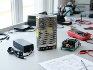
A PoE Adapter can deliver the correct voltage and enough power while still becoming the wrong component for a multi-gigabit Ethernet product.
For OEM teams moving from 1G to 2.5G, 5G or 10G Ethernet, the critical question is no longer only:
“Will the powered device turn on?”
It is also:
“Will the complete power-and-data path preserve the Ethernet channel performance required for the target data rate?”
That distinction matters because Power over Ethernet and BASE-T data transmission use the same balanced twisted-pair infrastructure. IEEE 802.3bz defines 2.5GBASE-T and 5GBASE-T operation over balanced twisted-pair transmission media, while 10GBASE-T is specified for operation over balanced twisted-pair structured cabling with a reach of up to 100 meters.
For that reason, when we evaluate a PoE Adapter for a multi-gigabit OEM project, we treat it as two functions that must coexist:
- a power-conversion and PoE power-sourcing function; and
- a high-speed Ethernet data path.
A successful design has to satisfy both at the same time.
This guide focuses on that intersection. We will explain what changes when an OEM device needs 2.5G, 5G or 10G Ethernet, which signal-integrity mechanisms deserve attention, how PoE current and cable temperature can interact with data performance, and how we recommend structuring system-level validation.
The Short Answer: A Multi-Gig PoE Adapter Must Be Evaluated as Part of the Ethernet Channel
If a project is evaluated only from the power side, engineers may check output voltage, available wattage, protection functions and the required PoE standard.
For a 2.5G/5G/10G device, that is incomplete.
A PoE Adapter is physically located in the Ethernet path. Depending on its architecture, its RJ45 interfaces, magnetics, PCB routing, protection components and internal transitions become part of the electrical path seen by the Ethernet PHY.
At the same time, DC current for PoE is being carried through the same cabling system.
Therefore, we recommend that OEM validation answer four separate questions:
| Validation Area | Main Question |
| PoE interoperability | Does the PSE/PD relationship detect, classify and power correctly? |
| DC power delivery | Does sufficient usable power reach the PD under realistic cable, load and temperature conditions? |
| Ethernet channel performance | Does the complete path maintain the required 2.5G/5G/10G rate reliably? |
| Combined-condition robustness | Does the link remain stable while carrying realistic PoE current under thermal and channel stress? |
Passing one of these does not prove the others.
For example, a device that powers correctly at 60W has not automatically demonstrated 5G Ethernet performance. Likewise, a 10G link established through a short bench cable does not prove that the PoE power path will remain stable at high load over the intended installed channel.
That separation is the foundation of a useful multi-gig PoE validation plan.
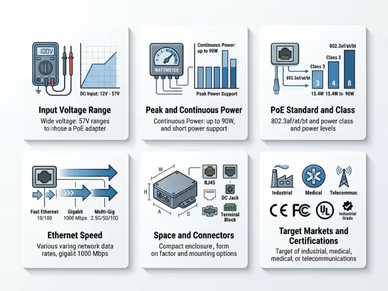
Why 2.5G and 5G Are Not Simply “Faster 1G”
IEEE 802.3bz defines 2.5GBASE-T and 5GBASE-T over balanced twisted-pair media. TIA subsequently published TSB-5021 to provide guidance for evaluating installed Category 5e and Category 6 cabling for 2.5GBASE-T and 5GBASE-T, including visual inspection and field-testing guidance.
This is especially relevant to PoE Adapter projects because many multi-gig applications are upgrades rather than completely new installations.
A new wireless access point, industrial gateway, video endpoint or edge device may be capable of 2.5G or 5G Ethernet while being connected to cabling that was originally installed for 1G.
The real channel can include:
Network source → patch cord → PoE Adapter → structured cabling → connectors → patch cord → powered device
Every element contributes to the final electrical channel.
At 1G, a particular connector transition or PCB discontinuity may leave enough operating margin that the problem never becomes visible. At a higher rate, the same interface can consume more of the available channel margin.
That is why we do not use a simple “link up” result as proof that a PoE Adapter is suitable for multi-gig Ethernet.
A short laboratory cable can make a marginal integration look healthy. Move the same hardware to a longer channel, a warmer cable bundle or a different endpoint PHY, and the available margin may change.
For an OEM project, the practical rule is:
The target Ethernet rate should be part of the PoE Adapter specification from the beginning, not treated as an assumed property of the RJ45 interface.
Why 10GBASE-T Raises the Bar Again
10GBASE-T places greater demands on the copper channel.
IEEE technical material for 10GBASE-T defines link-segment characteristics that include insertion loss, return loss and coupling parameters such as near-end and far-end crosstalk. Ethernet Alliance technical material also identifies insertion loss and alien crosstalk as important considerations for 10GBASE-T cabling.
For a PoE Adapter, that changes how we look at the components between the two Ethernet ports.
An RJ45 connector is not simply “an RJ45.”
A PCB trace is not automatically acceptable because electrical continuity exists.
Magnetics cannot be judged only by whether they worked in a 1G design.
A protection network that performs well during surge or ESD testing can still introduce parasitic effects that must be considered in a high-speed signal path.
At 10G, impedance discontinuities, excessive attenuation, pair asymmetry, crosstalk and parasitic capacitance or inductance can reduce the signal margin available to the PHY.
Therefore, a claim such as “10G Ethernet support” should correspond to a defined design and validation condition rather than merely indicating that the product uses Ethernet connectors.
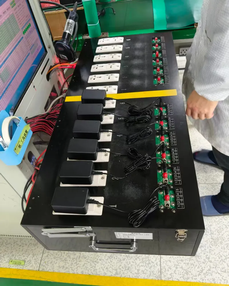
The Six Signal-Integrity Areas We Examine in a Multi-Gig PoE Adapter
1. Insertion Loss: How Much Useful Signal Is Lost Through the Path?
Insertion loss describes attenuation through the transmission path.
From an OEM perspective, the key issue is cumulative loss.
The signal does not encounter only the PoE Adapter. It travels through a complete path that may include multiple connectors, patch cords, structured cable, magnetics and PCB transitions.
The PoE Adapter adds its own contribution.
This explains why short-cable testing can produce false confidence.
Suppose an engineering team connects the adapter between two devices using one-meter patch cords. The cable contribution to total loss is relatively small, so the complete system may establish the target link rate easily.
That result does not tell us how much margin remains.
When the same adapter is deployed in a much longer channel, the cable itself consumes more of the available budget. Loss contributed by the adapter then becomes more significant in the total system.
For that reason, we prefer two stages of testing:
- short reference-channel testingto establish a clean baseline; and
- representative long-channel testingto evaluate the product closer to the intended deployment condition.
The objective is not simply to prove that the PoE Adapter works in the easiest possible configuration. It is to determine whether it leaves enough channel margin for the real application.
2. Return Loss: Are Discontinuities Reflecting Energy Back Toward the Transmitter?
Balanced twisted-pair Ethernet depends on a controlled transmission environment. When the signal encounters an impedance discontinuity, part of its energy can be reflected.
Return loss is one way of characterizing this behavior.
Within a PoE Adapter, discontinuities can be influenced by:
- RJ45 connector geometry;
- magnetics;
- PCB trace geometry;
- vias and layer transitions;
- stubs;
- component pads;
- protection components;
- transitions between the connector, magnetics and internal routing.
The challenge is that some of these components may be required for reasons unrelated to data transmission.
For example, a protection network may be necessary to meet an EMC or surge requirement. The PoE circuitry must also connect to the appropriate power path. Mechanical constraints may determine connector placement.
We therefore cannot optimize the high-frequency data path independently from the power and protection architecture.
The goal is to create a controlled interface in which those functions are added without introducing unacceptable disturbance to the Ethernet path.
3. Near-End and Far-End Crosstalk: Are the Four Pairs Interfering With Each Other?
BASE-T Ethernet uses multiple balanced pairs simultaneously.
That means pair-to-pair coupling matters.
IEEE 10GBASE-T link-segment material includes requirements addressing near-end and far-end crosstalk behavior because unwanted coupling reduces the signal-to-noise margin available to the receiver.
For a PoE Adapter, this means pin continuity is not enough.
Two PCB assemblies can have the same connectors and identical pin mapping while presenting very different high-frequency behavior.
During design review, we therefore pay attention to issues such as:
- pair symmetry;
- unnecessary parallel routing;
- spacing between high-speed pairs;
- vias and transitions;
- magnetics placement;
- protection-component placement;
- routing around PoE power-extraction or injection nodes.
A PHY may be capable of compensating for significant channel impairment, but relying on PHY equalization to rescue an unnecessarily poor interconnect is not the same as designing a robust channel.
For an OEM product that may operate with different switches, PHYs and cabling environments, preserving margin is more useful than proving that one laboratory configuration can recover the signal.
4. Alien Crosstalk: What Happens Outside the Adapter?
Alien crosstalk is interference coupled from neighboring cables rather than from pairs within the same cable.
This becomes increasingly relevant as data rates rise and cable density increases.
Ethernet Alliance material discussing 10GBASE-T identifies alien crosstalk as an important part of the channel noise environment, while TIA’s 2.5G/5G guidance recognizes that installed Category 5e and Category 6 cabling may require further assessment for multi-gig applications.
The PoE Adapter cannot control an entire building’s cabling plant.
That is precisely why the adapter should not consume unnecessary channel margin.
Consider two validation philosophies.
The first asks:
“Can we get a 10G link using this adapter and a short cable?”
The second asks:
“How much system margin are we preserving for the channel conditions that the final deployment may introduce?”
For OEM equipment, the second question is more useful.
Real installations can include long cable runs, bundled cables, patch panels, multiple connectors and different cabling generations. A product that operates only under pristine bench conditions leaves too little tolerance for variables outside the OEM’s control.
5. DC Resistance and Resistance Unbalance: Power Delivery Changes the Electrical Problem
PoE adds DC current to the balanced cabling used for data.
Resistance therefore matters for power loss and voltage drop, while resistance unbalance can affect how current is distributed.
TIA has specifically addressed DC resistance and resistance unbalance in work related to power delivery over balanced twisted-pair cabling. IEEE 802.3bt development also addressed current and resistance unbalance in four-pair powering.
For the PoE Adapter, relevant contributors can include:
- connector contact resistance;
- PCB copper paths;
- solder-joint consistency;
- magnetics winding and center-tap structures;
- current-sharing behavior;
- cable conductor resistance;
- patch-panel and connector resistance in the installed channel.
This creates an important difference between short-bench testing and system testing.
On a short cable, resistance is low and voltage drop may be small. Under that condition, the powered device may receive comfortable voltage and power margin.
A long cable changes the picture.
The same load current produces more loss in a higher-resistance path. That loss is dissipated as heat, and the voltage available at the remote end can change.
Therefore, when we investigate a multi-gig PoE system, DC resistance is not treated as only a cable specification. It is part of the end-to-end power-delivery condition.
6. Common-Mode Behavior: Power and Data Must Share the Interface Without Losing Balance
PoE works because DC power can coexist with differential Ethernet signaling.
That architecture makes balance important.
If routing, components or protection networks introduce excessive asymmetry, some differential energy can be converted into common-mode energy, or the path may become more sensitive to common-mode disturbances.
This is where high-speed data design and EMC design begin to overlap.
A change introduced to improve ESD or surge performance can alter parasitic capacitance.
A layout change made for data performance can change return-current paths.
A different magnetics structure can affect both the Ethernet path and PoE current path.
For this reason, we prefer an iterative engineering workflow in which power, Ethernet and EMC performance are reviewed around the same physical interface.
Treating them as three unrelated qualification activities can allow one late-stage fix to disturb another previously passing condition.

PoE Current Creates Heat, and Heat Can Change the Data Channel
One of the most easily overlooked interactions between high-power PoE and high-speed Ethernet is temperature.
When current passes through resistance, part of the electrical power becomes heat. UL’s guidance for Limited Power cabling specifically notes that higher power increases heat generation and that bundling can make thermal conditions more demanding.
TIA’s PoE cabling work has likewise addressed higher current, cable bundles and different installation conditions.
This matters to multi-gig Ethernet because temperature is not isolated from electrical channel performance.
As conductor temperature rises, resistance changes. Higher cable temperatures can also affect insertion loss.
Therefore, the power-delivery condition can change the environment in which the Ethernet signal is operating.
This is why we do not consider the following sequence sufficient for a demanding project:
Test 10G data → pass → test maximum PoE load → pass → finish validation.
The two conditions should also be combined.
A more representative development sequence is:
- establish the target Ethernet rate;
- connect a representative channel;
- apply a realistic PoE load;
- allow the system to reach a stable thermal condition;
- run sustained Ethernet traffic;
- monitor errors, retraining and link stability;
- repeat at the relevant environmental corners.
We intentionally do not recommend a universal cable-length derating percentage or universal temperature limit here.
Those values depend on the applicable cable construction, conductor size, bundle size, installation method, PoE current, equipment specification and standards governing the final application.
A useful engineering guide should not replace those variables with an invented rule of thumb.
Why “It Negotiated at 10G” Is Not Enough
A common development shortcut is to connect the PoE Adapter between two 10G-capable devices, wait for auto-negotiation and confirm that the operating system reports a 10G link.
That is a useful first test.
It is not a complete validation.
A link can establish while operating with limited margin. Depending on the PHY, cabling and system, a marginal channel may later appear as:
- intermittent link retraining;
- packet errors;
- reduced throughput;
- unexpected link drops;
- fallback to a lower Ethernet rate;
- instability after warm-up;
- sensitivity to cable replacement.
A stronger test plan therefore separates link establishment from link quality and stability.
| Validation Item | What It Shows | Why We Check It |
| Negotiated Ethernet rate | Endpoints can establish the requested mode | Necessary baseline |
| Sustained bidirectional traffic | Link operates under real traffic | Exposes failures hidden at idle |
| Packet/error counters | Whether errors accumulate during operation | Indicates margin problems |
| Link retraining / drop count | Whether the PHY repeatedly loses or re-establishes the link | Reveals instability that a one-time link check misses |
| Throughput under sustained load | Whether useful data rate remains stable over time | Helps distinguish nominal link speed from usable performance |
| Full PoE load plus traffic | Whether power delivery and data transmission remain stable together | Exercises the condition the product will actually see |
| Warm steady-state operation | Whether behavior changes after the adapter, cable and endpoints heat up | Exposes temperature-dependent margin loss |
| Cable and endpoint substitution | Whether performance depends on one unusually favorable setup | Reduces the risk of validating only a single PHY/cable combination |
The exact error limits and test duration should come from the OEM’s system requirements. We do not recommend inventing a universal packet-error threshold for every 2.5G, 5G or 10G product, because the acceptable result depends on the application, PHY implementation, traffic pattern and validation method.
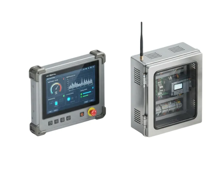
A Practical Multi-Gig Validation Matrix for the PoE Adapter Path
For development work, we prefer to change one stress factor at a time before combining them. That makes failures easier to diagnose and prevents a marginal result from being hidden by too many variables.
A useful matrix can look like this:
| Test Condition | Data Condition | Power Condition | What We Want to Learn |
| Short reference channel | Target Ethernet rate | Normal operating load | Establish a clean baseline |
| Representative installed channel | Target Ethernet rate | Normal operating load | Check channel margin closer to deployment |
| Representative channel | Sustained bidirectional traffic | High realistic PD load | Verify simultaneous data and power operation |
| Warm steady state | Sustained traffic | High realistic PD load | Detect thermal sensitivity |
| Cable substitution | Target rate and traffic | Same PD load | Check dependence on cable construction or termination quality |
| Endpoint substitution | Target rate and traffic | Same PD load | Check interoperability with different PHY implementations |
| EMC/protection recheck | Target rate and traffic | Representative load | Confirm that protection or EMC changes have not degraded the data path |
This matrix is intentionally different from a generic PoE functional test. Its purpose is to expose interactions that only appear when high data rate, channel loss, DC current and temperature exist at the same time.
For 2.5G and 5G upgrades, the installed cabling deserves particular attention. TIA TSB-5021 was created specifically to guide assessment of installed Category 5e and Category 6 cabling for 2.5GBASE-T and 5GBASE-T. That is an important reminder that the adapter cannot be evaluated in isolation from the cabling it will join.
For 10GBASE-T, the same principle becomes stricter. Ethernet Alliance technical material highlights insertion loss and alien crosstalk as primary cabling considerations for 10GBASE-T operation. If an adapter adds avoidable loss or discontinuity, it consumes margin that the rest of the installed channel may need.
How We Troubleshoot a PoE System That Powers Correctly but Cannot Hold Multi-Gig Speed
One of the most useful engineering situations is also one of the most confusing: the powered device starts normally, PoE negotiation appears correct, but 2.5G, 5G or 10G operation is unstable.
When that happens, replacing the power supply immediately can waste time. We prefer a controlled isolation sequence.
Step 1: Establish a Data-Only Reference
First, create the cleanest practical Ethernet path between the same endpoints without the PoE Adapter in the data path, if the system architecture permits it.
The purpose is not to reproduce the final product. It is to answer a diagnostic question:
Can the two endpoints and the selected cabling sustain the target rate without the adapter path?
If the answer is no, the root cause may already exist in the endpoints, cable, connectors or configuration. If the answer is yes and the problem appears only after the adapter is inserted, the investigation becomes more focused.
Step 2: Reduce Channel Stress Before Changing the Hardware
Use a known-good short cable configuration and repeat the target-rate test.
If the link becomes stable only when the channel is shortened, that points toward a margin problem rather than a simple functional incompatibility. The next question is then which element is consuming the margin: cable loss, connector transitions, adapter insertion loss, return loss, crosstalk, or a combination of them.
This A/B method is more informative than repeatedly reconnecting the same long channel and hoping for a different result.
Step 3: Compare Low and High PoE Load
Keep the Ethernet path unchanged and vary the PD load within the intended operating range.
If data behavior changes as PoE current rises, investigate the power-and-data interaction rather than treating the event as a purely digital networking fault. Relevant areas include voltage drop, contact resistance, current sharing, resistance unbalance, magnetics behavior and thermal rise.
This does not mean that higher current automatically causes a data failure. It means that a load-dependent failure gives the engineering team a valuable clue about where to look next.
Step 4: Compare Cold and Warm Operation
Run the same traffic test after the system reaches a representative steady-state temperature.
A link that is stable immediately after startup but begins retraining after warm-up should not be signed off based on the cold result. Higher conductor temperature can increase resistance, and industry guidance also recognizes the relationship between elevated cable temperature and insertion loss.
The practical point is simple: time at load is a test variable.
Step 5: Read Counters Before the Link Fails Completely
Do not wait for a visible disconnect.
PHY, switch or operating-system statistics may reveal CRC errors, retransmissions, link renegotiation or other warning signs before the user experiences a complete outage. The exact counters available depend on the equipment, but trending them during sustained traffic is much more useful than recording only “link up” or “link down.”
Step 6: Change One Endpoint or Cable at a Time
Multi-gig PHYs are designed to operate within standardized channel requirements, but implementations and recovery behavior are not identical in every product.
If a design passes only with one switch, one NIC and one short patch cord, we would treat that as a development clue rather than strong evidence of robust interoperability.
The objective is not to test every Ethernet product on the market. It is to avoid approving a design whose apparent success depends on one unusually favorable combination.
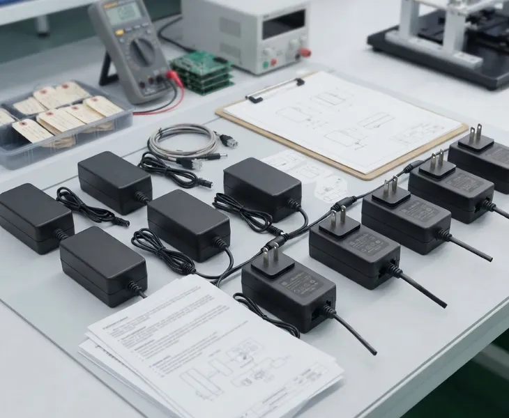
What a Meaningful “10G-Capable PoE Adapter” Claim Should Tell an OEM
For a product developer, the phrase 10G capable is useful only when it refers to a defined adapter design and a meaningful validation basis.
At minimum, we recommend confirming:
- the exact adapter model or hardware revision;
- the supported Ethernet rate, rather than assuming all models in a family are identical;
- the PoE standard and intended power range;
- whether all four data pairs are routed for the required BASE-T mode;
- the RJ45, magnetics and protection architecture used in the validated design;
- the channel configuration used during data testing;
- whether testing included sustained traffic rather than only auto-negotiation;
- whether PoE load was applied during the data test;
- whether warm operation was included where the application is thermally demanding;
- whether design changes to magnetics, PCB routing, protection parts or connectors trigger re-evaluation.
This is also why model-level documentation matters.
A manufacturer may offer 10/100, 1G and 10G products under the broad label “PoE Adapter.” Those products should not be treated as interchangeable. The data-path architecture required for a 100Mbps product is not evidence that a different model is suitable for 10GBASE-T.
For our own product discussions, we therefore ask customers to state the required Ethernet speed early. It affects component selection, layout decisions, interface design and the validation plan.
Design Changes That Deserve a Multi-Gig Recheck
Once a prototype has passed high-speed testing, it is tempting to regard the Ethernet path as finished. In practice, later changes can alter the same electrical path.
We would re-examine multi-gig performance when changes involve:
- RJ45 connector supplier or connector construction;
- Ethernet magnetics or integrated-magnetics connector;
- TVS, ESD or surge-protection components;
- PCB stack-up, trace geometry or routing layer;
- vias, stubs or connector breakout geometry;
- PoE injection circuitry around the magnetics center taps;
- copper thickness or current path relevant to PoE delivery;
- enclosure or thermal changes that materially change operating temperature;
- cable assemblies or pigtails supplied as part of the adapter configuration.
Not every change will cause a failure. The reason to recheck is that these items can influence insertion loss, return loss, balance, parasitic loading, crosstalk, resistance or temperature.
This is especially important for OEM programs that expect long production lifecycles. A substitute part that is electrically “equivalent” at low frequency may not be equivalent in a 10G data path. Component change control should therefore distinguish ordinary power-component substitutions from changes that touch the high-speed Ethernet interface.
How PoE Power Level and Ethernet Speed Should Be Specified Separately
Another common source of confusion is assuming that a higher-wattage PoE Adapter automatically supports a higher Ethernet rate.
These are different specifications.
A project may require high PoE power but only 1G data. Another project may require 10G data while the powered device consumes much less than the maximum power available from the adapter.
The system specification should therefore state both independently:
Power requirement: required IEEE PoE mode, usable PD power, voltage/current conditions and operating load.
Data requirement: 100M, 1G, 2.5G, 5G or 10G Ethernet, together with the intended cabling and validation conditions.
Keeping those requirements separate prevents a purchasing shortcut such as “choose the 100W model, so it must be the fastest model.” Wattage describes power capability; it does not by itself prove Ethernet channel capability.
Where Our Multi-Gig PoE Adapter Range Fits
For OEM teams that need to compare power and Ethernet requirements together, our PoE Adapter series includes different power levels and data-rate configurations rather than treating every PoE product as the same design.
At Quankang, one model relevant to this article is the PoE100-54A 100W PoE Adapter. Its official product information lists 90–290VAC input, 54VDC output, IEEE 802.3af/at/bt support and Ethernet transmission options from 10Mbps through 10Gbps.
Those specifications are useful starting points, but for an OEM project we still recommend validating the adapter in the customer’s actual system architecture. The powered device, switch or network source, cable category, installed length, connector count, PoE load, enclosure temperature and EMC environment all contribute to the final result.
That is the central engineering message of this guide: a multi-gig PoE Adapter should be selected as a power component and validated as part of a high-speed channel.

Frequently Asked Questions About Multi-Gig PoE Adapters
Can a PoE Adapter support 100W power but only 1G Ethernet?
Yes. Power capability and Ethernet data rate are separate product characteristics. A high-power PoE design is not automatically a multi-gig design. Always confirm the supported Ethernet rate for the exact model.
If a PoE Adapter has two RJ45 ports, does that mean it can pass 10G Ethernet?
No. Connector type alone does not establish the supported data rate. The complete path—including connector implementation, magnetics, PCB routing, protection components and other transitions—has to be suitable for the target Ethernet mode.
Is 2.5GBASE-T or 5GBASE-T guaranteed to work on existing Category 5e or Category 6 cabling?
It should not be treated as an unconditional guarantee. TIA published TSB-5021 specifically to provide guidance for assessing installed Category 5e and Category 6 cabling for 2.5GBASE-T and 5GBASE-T, including inspection and field-testing guidance. The actual installed channel condition matters.
Why can a 10G link work on a short cable but fail in the real installation?
A short cable consumes less of the channel’s loss budget and may hide weaknesses elsewhere in the path. A longer installed channel introduces more insertion loss and may also include patch panels, additional connectors, bundled cabling and external crosstalk conditions. The adapter’s contribution then becomes part of a more demanding total channel.
Does PoE current interfere directly with Ethernet data?
PoE is designed so that DC power and differential Ethernet signaling can coexist on balanced twisted-pair cabling. Problems arise when the implementation or channel has excessive resistance, resistance unbalance, loss, asymmetry, thermal rise or other impairments that reduce power or signal margin.
Why should we test Ethernet traffic while the PD is drawing power?
Because separate tests do not reproduce the combined operating condition. Applying realistic PoE current changes voltage drop and thermal conditions in the channel. Sustained traffic at the same time helps determine whether the system remains stable under the condition it will actually experience in service.
Does higher cable temperature affect multi-gig Ethernet performance?
It can. Higher conductor temperature increases resistance, and industry technical guidance recognizes that elevated cable temperature can increase insertion loss. That is one reason high-power PoE and multi-gig data should be evaluated together when the application includes long channels, cable bundles or elevated ambient temperatures.
Should we use packet throughput alone as the acceptance criterion?
No single measurement should carry the entire decision. Throughput is useful, but we also look at negotiated rate, error counters, link retraining, link drops, warm-up behavior and repeatability across representative channels. The OEM should define acceptance limits appropriate to the final application.
Do we need a special PoE Adapter for every 2.5G, 5G or 10G project?
Not necessarily. The requirement is that the exact adapter architecture support the target power and data conditions with adequate system margin. A validated standard model may be suitable. If mechanical, connector, protection, power or channel requirements differ, a customized design may be more appropriate.
Technical References
The engineering principles in this article are consistent with the following standards and technical guidance:
- TIA TSB-5021 guidance for installed Category 5e and Category 6 cabling supporting 2.5GBASE-T and 5GBASE-T
- Ethernet Alliance technical material on 10GBASE-T over twisted-pair copper
- UL Solutions guidance on Limited Power cabling for PoE applications
- Fluke Networks technical guidance on DC resistance unbalance for PoE
Final Engineering Takeaway
When Ethernet moves beyond 1G, a PoE Adapter cannot be evaluated only as an AC-DC power supply with RJ45 connectors.
For 2.5G, 5G and especially 10GBASE-T systems, it sits inside a balanced high-speed transmission path while simultaneously delivering DC power. That creates a coupled engineering problem involving insertion loss, return loss, crosstalk, balance, DC resistance, resistance unbalance, thermal rise, protection design and the behavior of the complete installed channel.
The most reliable development approach is therefore to avoid a single pass/fail question such as “Does it power on?” or “Did it negotiate at 10G?” Instead, establish a clean reference, test a representative channel, apply realistic PoE load, reach thermal steady state, run sustained traffic, monitor errors and retraining, and repeat the conditions that matter to the final deployment.
For OEM network equipment, wireless infrastructure, industrial gateways, security devices and other multi-gig products, this approach gives engineering teams something more valuable than a successful bench demonstration: evidence that the power-and-data path has been considered as one system.
Quankang supports PoE Adapter projects with model selection, electrical and mechanical customization, engineering review, EMC pre-testing and production support. If your device requires 2.5G, 5G or 10G Ethernet, send us the target data rate, PoE standard, PD power requirement, intended cable/channel condition and operating environment. We can review the requirement with you and help identify an appropriate standard or customized PoE Adapter for evaluation.