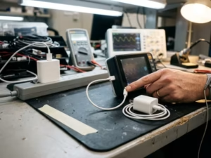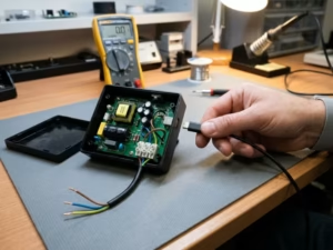

A prototype runs perfectly on the bench. The display stays stable, the sensors read clean, and the team feels ready for approval.
Then the unit enters the EMC lab. It fails conducted emissions in the first hour. Later, an ESD strike near a connector triggers a full reset.
The main board is not always the culprit. In many projects, I trace the problem to the power supply chain: a noisy front end, a long mains cable, a weak ground path, or a filter someone sized without checking leakage limits.
IEC 60601-1-2 sets the EMC requirements for medical electrical equipment and systems. It checks two things: how much noise your device emits, and how well it keeps working when interference hits it.
I have guided many medical device teams through this stage. This guide skips the full overview of the standard. It covers the requirements that matter most when you choose a power supply, design the system around it, and prepare for formal testing.
What IEC 60601-1-2 Really Means for Your Power Supply
Many teams treat IEC 60601-1-2 as a box to tick on a supplier datasheet. That habit causes trouble later. Before you compare power supplies, you need to know what the standard actually tests.
Two Standards, Two Different Jobs
IEC 60601-1 is the general safety standard. It covers electric shock, insulation, creepage distances, and leakage current.
IEC 60601-1-2 covers EMC. It asks two questions:
- Does your device emit too much electrical noise?
- Does it keep working safely when interference hits it?
Both standards depend on the same parts, and your power supply sits in the middle of both.
The Lab Tests Your Device, Not Your Power Supply
I raise this point early with every client. The EMC lab tests the complete device or system. It runs the unit with its real enclosure, real cables, real load, and real grounding.
Your power supply may come with a clean test report. That report shows how the supply performed in the vendor’s setup. It does not show how it will perform inside your product.
I have seen a supply pass on its own, then push a full system over the conducted emissions limit. The cause was a long internal harness that acted like an antenna.
I have also seen a well-rated supply reset during ESD testing. The enclosure ground had a weak bond, and the discharge found its way into the output.
A compliant power supply lowers your risk. It does not make your device compliant on its own.
This should change how you choose one. A “medical-grade” label tells you where to start looking. It does not tell you whether the supply fits your system, your leakage budget, or your use environment. If you are comparing options, start with a focused range of medical power supplies, then look past the label before you move into system-level validation.

Why the Power Supply Is Often the EMC Trouble Spot
When a medical device fails EMC testing, I often start my debugging at the power supply. Many hidden EMC paths come together there. The reasons below explain why this part causes trouble so often.
It Makes Noise and Lets Noise In
A switching power supply turns current on and off tens or hundreds of thousands of times per second. Each sharp edge creates harmonics that travel back down the mains cable as conducted noise. At higher frequencies, they also radiate.
The switch node causes much of this. It couples through small parasitic capacitances into the heatsink, the chassis, and the transformer. That coupling creates common-mode current, and common-mode current is hard to filter.
The power supply also works in the other direction. It connects your device to the mains, so surges, fast transients, and RF energy enter the device through it. One part is both your biggest noise source and your main entry point for interference.

Cables Often Radiate More Than the Module
Many engineers focus on the power module and miss the wiring around it. In my experience, the cables often cause more radiated failures than the module does.
A mains cord or an I/O lead becomes an efficient antenna once its length matches a fraction of a noisy frequency. Common-mode current on its shield or conductors turns into radiated emissions.
Watch for these weak points:
- DC output wires routed next to signal or sensor cables
- Pigtail shield connections instead of full 360° bonds
- Ground returns that loop around the enclosure rather than taking a short path
- Painted or anodized panels that break the metal-to-metal contact
These details rarely appear on a schematic, but the lab finds them.
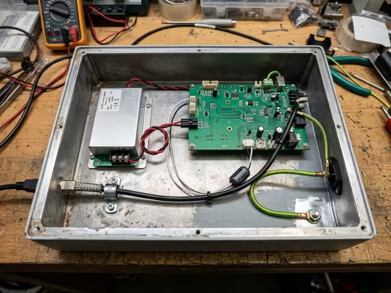
Medical Rules Limit Your Filter Options
On an industrial product, I can often fix a conducted emissions problem with larger Y-capacitors. That option is limited in medical design.
Y-capacitors send noise current to protective earth, and that current counts as leakage. IEC 60601-1 sets strict limits on touch current and patient leakage. A CF-type applied part, for example, allows only 10 µA of patient leakage in normal condition.
Isolation adds another limit. A supply rated for 2 MOPP needs wide creepage distances and a high-isolation transformer, which leaves less room for filter parts. You need to weigh EMI performance and electrical safety together.
A Clean Bench Hides Weak Spots
Your bench is a quiet place. The power is stable, nobody walks across a carpet, and no radio sits nearby. A design can look solid there for months.
The lab removes that comfort. It fires ESD at the enclosure and connectors. It applies RF fields across a wide frequency band. It sends fast transient bursts and surges into the mains port. It drops the supply voltage to zero for a few cycles, then restores it.
Each test pushes the power chain to its limits. A feedback loop with little phase margin may oscillate under RF. A hold-up capacitor that looked fine may not cover a 0% dip. A supervisor circuit may trigger a reset that the device never shows on the bench.
These failures come from design limits that the bench never tests. The lab is usually the first place they show up.
The EMC Requirements That Matter Most in Real Projects
IEC 60601-1-2 covers many tests, and you don’t need to memorize them all. In real projects, four areas cause most of the delays I see. The power supply plays a role in every one of them.
I group these tests by the question each one asks. That framing makes it easier to plan your design work before you book the lab.
Emissions: Can Your Device Stay Electrically Quiet?
Emission tests measure the noise your device sends out. Conducted emissions cover the mains port from 150 kHz to 30 MHz. Radiated emissions cover the space around the device, usually from 30 MHz to 1 GHz. Many medical devices, including all home-use devices, must meet CISPR 11 Class B limits, which are the stricter residential-style limits.
Four design choices shape your result:
- Topology. Hard-switched flyback designs ring more than quasi-resonant or LLC designs.
- Input filter. Common-mode chokes and X/Y-capacitors set your conducted margin.
- Layout. A tight hot loop around the switch and rectifier cuts noise at the source.
- Cables and shielding. These decide how much of that noise radiates.
So why does a module pass on its own but fail in your system? The vendor tested it with short leads, a resistive load, and a clean ground plane. Your product adds a 2-meter mains cord, a motor driver, and a plastic housing. Each of these changes the common-mode path.
I aim for at least 6 dB of margin in pre-compliance scans. Lab setups vary, and a 2 dB margin can disappear on test day.
Emissions show how loud your device is. Immunity tests flip the question and ask how well your device handles noise from everything else.
RF Immunity: Can It Keep Working Around Wireless Energy?
RF immunity checks whether outside radio energy disturbs your device. The radiated test exposes the unit to fields from 80 MHz to 2.7 GHz. The field strength is 3 V/m for professional healthcare settings and 10 V/m for home use. Edition 4 also adds proximity tests that mimic phones and radios held close to the device, at up to 28 V/m. The conducted test injects RF onto cables from 150 kHz to 80 MHz.
Inside the power chain, RF does its damage in a few predictable places:
- Control loop. Feedback circuits can rectify RF and shift the output voltage.
- Feedback stability. A loop with thin phase margin may start to oscillate.
- Cable coupling. Long cables pick up RF and carry it straight to sensitive nodes.
- Enclosure bonding. Loose seams and gaps let fields reach the board.
On one patient monitor, I watched the 5 V rail drift by 300 mV at a single narrow frequency. An unfiltered optocoupler feedback trace ran right past a cable entry. A small capacitor and a shorter trace fixed it.
Run the full frequency sweep with real cables attached. Narrowband failures hide easily in quick scans.
RF tests apply steady stress. The next group hits the device with sudden events.
ESD, EFT, Surge and Dips: Can It Survive Real Electrical Disturbances?
These tests copy events that happen every day in hospitals and homes. Real scenes explain them best:
- ESD. A nurse walks across a vinyl floor and touches a display bezel. The plastic enclosure stores charge, and the spark jumps to the nearest metal, often a USB port or a screw head. The standard calls for ±8 kV contact and ±15 kV air discharge.
- EFT (fast transients). A relay switches off a pump or compressor on the same circuit. That throws bursts of fast spikes onto the mains at ±2 kV.
- Surge. Lightning strikes near the building, or the utility switches a large load. Your input sees ±1 kV line-to-line and ±2 kV line-to-earth.
- Dips and interruptions. The hospital loses mains power and transfers to its backup generator. Your supply sees a deep dip, then an outage. The test includes a full interruption of up to 5 seconds.
The power supply shows the damage in a few typical ways:
- The microcontroller resets because a rail dips below its threshold.
- An output glitches and triggers a false alarm or a motor misfire.
- The output drops out because hold-up time runs short.
- Overvoltage or overcurrent protection latches off and needs a manual restart.
- The device recovers, but into the wrong state, with lost settings or a frozen display.
The last one worries me most. A clean reboot is often acceptable. A device that comes back silently in the wrong mode is not.
All of this raises a practical question: how do you decide whether a reaction counts as a failure?
Performance Criteria: What Counts as a Pass Is Not Always Obvious
Many engineers know the A/B/C criteria from commercial EMC standards:
- Criterion A: The device works normally during and after the test.
- Criterion B: It degrades briefly but recovers on its own.
- Criterion C: It loses function and needs an operator or a reset to recover.
IEC 60601-1-2 takes a different route. It doesn’t give you fixed A/B/C rules. You define the acceptable response through your risk analysis, based on basic safety and essential performance.
That means a reaction can still pass. A blood pressure monitor that blanks its screen for one second during ESD may pass. An infusion pump that changes its flow rate for one second may fail. The difference is what the patient experiences.
So write your pass criteria before you book the lab. List each essential performance function, its allowed deviation, and the recovery behavior you accept. Get your test lab and regulatory team to agree on that list early.
The table below links each test area to the power supply decisions it usually affects:
Test Category | Common Power Supply Risk | Typical Lab Failure Mode | Design/Selection Focus |
|---|---|---|---|
Conducted & radiated emissions | Switching noise, common-mode current | Peaks over Class B limits, often at low MHz or 30–300 MHz | Input filter, layout, cable routing, shielding |
RF immunity (radiated & conducted) | RF rectification in feedback, cable pickup | Output drift or sensor errors at narrow frequencies | Loop phase margin, feedback filtering, enclosure bonding |
ESD | Discharge path through ports and outputs | Resets, frozen displays, latched faults | Grounding, 360° shield bonds, TVS at connectors |
EFT & surge | Mains energy entering the input stage | Protection trips, output glitches, component stress | MOV/TVS input protection, filter ratings |
Voltage dips & interruptions | Short hold-up time | Unplanned shutdown, wrong restart state | Hold-up capacitance, brownout handling, defined restart behavior |
This kind of mapping helps teams spot design risk much earlier than a formal lab report would.
What Makes Medical EMC Harder Than Commercial EMC
Engineers who come from consumer or IT products often expect medical EMC to feel familiar. The tests look similar, and the labs use the same equipment. But three issues change the job, and the power supply sits at the center of each one.
You Define What “Working” Means
A commercial product passes or fails against fixed criteria. Medical design adds a step before testing. You must define your device’s essential performance and decide which reactions put a patient at risk.
That task falls on your team, not the lab. If you leave it vague, the lab can’t judge your results, and your reviewer will ask hard questions. I treat this definition as a design input. It tells me how much hold-up time, filtering, and recovery logic the power chain needs.
The Patient Becomes Part of the Circuit
A laptop never connects to a human body. A medical device often does, through ECG leads, SpO2 probes, or electrode pads.
Those patient cables act like antennas. They pick up RF energy and carry ESD current straight into sensitive front ends. A small disturbance that a printer would ignore can distort a heart signal or trigger a false alarm. Operators also touch screens, knobs, and ports during treatment, which adds more discharge paths. Every connection to a person raises the stakes.
Leakage Limits Tie Your Hands
On an IT power supply, designers often add Y-capacitance freely to pass emissions. Medical safety rules take much of that freedom away.
Every Y-capacitor that bridges the isolation barrier adds leakage current. The more patient protection your design needs, the smaller your capacitor budget gets. You also need wider spacing and a stronger transformer barrier, which can raise winding capacitance and give common-mode noise a new path. So you end up fighting noise with layout, chokes, and topology instead of extra capacitance.
Home Use Adds Another Layer
Home healthcare devices face some of the toughest conditions. Nobody controls the environment. A device may share an outlet with a cheap phone charger, sit next to a Wi-Fi router, or run from a socket with no proper earth. Users also lack training.
That is why I don’t copy a commercial EMC plan into a medical project. The tests may look the same, but the design margins need to be much wider.
How to Evaluate a Power Supply Before You Commit
Choosing a power supply for a medical device works like hiring a key team member. A good résumé helps, but you still check references and run a trial. The four checks below help you do the same before the supply goes into your design. If you are still narrowing down candidates, a structured review of available power supply products makes the comparison much easier.
Look Past the “Medical-Grade” Label
“Medical-grade” sounds reassuring, but no standard defines the term. One vendor uses it for a supply with a full IEC 60601-1-2 test report. Another uses it for a supply that only meets IEC 60601-1 safety rules.
I treat the label as a filter, not a verdict. It tells me the vendor understands the market. It doesn’t tell me how the supply behaves under ESD, surge, or a 0% dip.
So ask two questions every time:
- What tests did this supply actually pass?
- Under what conditions did it pass them?
If the vendor can’t answer both clearly, keep looking. A strong datasheet with no test evidence behind it will cost you more in the lab than it saves you on the purchase order.
The answers to those questions come from documents. You need to know which ones to request and what to look for inside them.
Request the Right Compliance Evidence
A short compliance statement on a datasheet tells you very little. Ask the vendor for the full package, and read it closely. It also helps to understand how the supplier supports design verification, production control, and test consistency through its facilities.
Here is what I request on every project:
- The latest test report or declaration. Check the edition. You want IEC 60601-1-2:2014 with Amendment 1 (2020), not an older edition.
- Test conditions. Find out who ran the tests, in which lab, and with what setup.
- Input range tested. A supply rated for 90–264 VAC should show results at both low and high line.
- Load conditions. Look for tests at light load and full load. Emissions often peak at one end.
- Grounding and installation. Note whether the vendor tested the supply as Class I or Class II, and on which ground plane.
- Leakage current specs. Get earth, touch, and patient leakage figures in microamps.
- Isolation rating. Confirm 2 MOPP for patient-connected designs, or 1 MOPP plus 1 MOOP where that fits your risk analysis.
- Representativeness. Ask whether the test setup resembles your use environment, such as home use versus a professional facility.
One gap in this list can force you to retest at system level. Find the gap now, while switching suppliers is still cheap.
Good paperwork still describes the vendor’s setup, not yours. Your next step is to find out how sensitive the supply is to the system around it.

Check Integration Sensitivity, Not Just the Datasheet
I have put the same supply into two products and seen two very different results. One passed radiated emissions with 8 dB of margin. The other failed by 4 dB at 120 MHz.
The supply didn’t change. The system around it did.
Five factors drive most of that difference:
- Enclosure. A metal chassis contains fields. A plastic housing lets them out.
- Harness length. A 15 cm DC lead behaves very differently from a 60 cm lead that loops around a motor.
- PCB layout. Long return paths on your downstream board create new noise loops.
- Grounding strategy. Single-point and multi-point grounding change where common-mode current flows.
- Peripheral interfaces. USB, Ethernet, and patient cables add antennas and ESD entry points.
So test the supply in a rough version of your real product early. A cardboard-and-copper-tape mockup with real cables tells you more than any datasheet.
Each of these factors points to a bigger idea. Your power supply isn’t a standalone part. It’s one piece of a larger EMC design.
Treat the Power Supply as Part of Your EMC Architecture
Many teams pick a power supply the way they pick a screw. Procurement compares price and lead time, then engineering drops it into the design. That habit causes late failures.
Treat the supply as a core part of your EMC architecture. Plan these five elements together:
- Front-end filter. Decide whether the supply’s internal filter is enough, or whether you need an external IEC inlet filter.
- Cable strategy. Set cable lengths, routing paths, and separation from signal lines early.
- Shielding. Plan where shields terminate and how they bond to the chassis.
- Grounding. Map the protective earth path and the noise return path on one drawing.
- Isolation and leakage budget. Split your allowed leakage across the supply, the external filter, and any other Y-capacitance.
That last point catches many teams. If the supply already uses 80% of your leakage budget, you have little room to add filtering later.
I ask every client to sketch one block diagram showing all five elements. That single page often exposes a conflict weeks before the lab would.
The table below sums up how to move from trusting a label to checking real evidence:
Evaluation Item | What a Label Alone Misses | A More Reliable Way to Check |
|---|---|---|
EMC compliance | Which edition, which tests, which limits | Read the full test report and confirm IEC 60601-1-2:2014+A1:2020 |
Emissions margin | Margin under your load and cable setup | Run pre-compliance scans with your real harness and load |
Immunity behavior | How the output reacts during ESD, surge, and dips | Ask for performance data during each test, not just “pass” |
Input range | Whether both low and high line were tested | Check the test conditions page for each input voltage |
Leakage current | Real values versus your total budget | Get measured figures in µA and add up all system sources |
Isolation | Patient protection level | Confirm the MOPP/MOOP rating and the safety certificate |
Use environment | Professional versus home healthcare levels | Match the test levels to your intended use environment |
Integration risk | Effects of your enclosure, layout, and grounding | Test in an early mockup of your real product |
Five Mistakes That Push EMC Failures to the End of a Project
Most late EMC failures don’t come from bad engineering. They come from reasonable assumptions that nobody checked in time.
I see the same five mistakes on project after project. Each one has a cheap fix if you catch it early, and an expensive one if the lab catches it first.
Mistake 1: Trusting the Supply’s Report to Cover the Whole Device
The assumption: The power supply passed IEC 60601-1-2, so the device will pass too.
What happens: The team skips system-level pre-compliance work and books the lab with confidence. Radiated emissions then fail at 80 MHz. The cause is a display cable and a motor driver that the supply vendor never tested. The schedule slips while the team scrambles for ferrites and shielding.
The better approach: Treat the supply report as proof that one part behaves well. Start system-level pre-compliance scans with your first working prototype. Budget time for at least one fix cycle before the formal test.
Mistake 2: Ignoring Cables Until the Lab Measures Them
The assumption: Cables are just wires. You can sort out routing during final assembly.
What happens: Cable length and routing decide which frequencies radiate. They also decide where ESD and RF energy enter. A sensor lead that runs beside the DC output picks up switching noise. A patient cable with a loose shield termination carries RF straight into the analog front end. The lab finds these problems at the most expensive moment.
The better approach: Make cable lengths, routing paths, and shield terminations part of the design. Test with production-length cables, not short bench leads. Fix the routing in place on your prototype so every test run matches.
Mistake 3: Adding Filters Without Checking Leakage
The assumption: If conducted emissions fail, add Y-capacitance until the peak drops.
What happens: Emissions pass, and then the safety test fails. Each added Y-capacitor raises earth and touch leakage. On a patient-connected design, a ten-minute bench fix can break your IEC 60601-1 compliance. Now you have two failures instead of one.
The better approach: Keep a running leakage budget for the whole system. Check the remaining headroom before you add any capacitance across the barrier. When the budget runs tight, use a common-mode choke, a cleaner layout, or a quieter topology instead.
Mistake 4: Writing Pass/Fail Criteria After Testing Starts
The assumption: The lab will tell you whether the device passed.
What happens: The lab reports what it sees. It doesn’t judge your clinical risk. Suppose your device reboots in four seconds during a voltage interruption and shows a brief error message. Is that acceptable? Without written criteria, engineering, quality, and regulatory may give three different answers. Your reviewer may raise the same question months later.
The better approach: Write your immunity pass criteria during design. For each essential performance function, define three things:
- The allowed deviation
- The maximum recovery time
- Whether an operator may step in
Send this document to the lab before test day.
Mistake 5: Starting EMC Work After the Design Is Frozen
The assumption: EMC is a final check. Finish the mechanical and harness design first, then test.
What happens: Every fix now costs real money. A missing chassis bond point means a new sheet-metal part. A shield that needs a 360° termination means a new connector and a new harness drawing. A change to a molded enclosure can take weeks of tooling work. Many teams settle for clip-on ferrites and copper tape, which then complicate production.
The better approach: Run EMC checks alongside mechanical design. Review grounding, bond points, seam overlaps, and connector choices at every design review. A near-field probe scan on an early mockup costs you an afternoon. A tooling change can cost you a quarter.
All five mistakes share one pattern. Each one delays a decision until the lab forces it. If you move those decisions earlier, the formal test confirms your design instead of exposing it.
A Practical Pre-Compliance Checklist
I go through this list with every team about four to six weeks before their formal EMC booking. Most items take hours, not weeks. Skipping one can cost you a full retest.
- Confirm your target markets and the edition each one expects.
The EU, the US, and other regions may reference different editions or national deviations. Write down the exact edition, amendment, and test levels for each market. Then plan one test campaign that covers them all. - Define essential performance before immunity testing.
List every function that protects the patient, along with its allowed deviation. Your hold-up time, filtering, and recovery logic depend on this list. - Review your leakage-current budget before you finalize EMI filters.
Add up every source: the supply, the inlet filter, and any Y-capacitors on your boards. I like to keep 20–30% headroom. Late emissions fixes often need it. - Check cable routing and enclosure bonding early.
Set cable lengths and routing paths on your prototype, and fix them in place. Measure each bond point with a milliohm meter. Paint and anodizing on mating surfaces break more designs than most teams expect. - Verify the power supply test evidence, not just the label.
Read the full report. Confirm that the edition, input range, load conditions, and test levels match your use environment. - Run pre-compliance testing before design freeze.
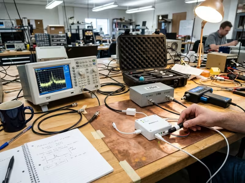
A LISN, a near-field probe set, and a rented spectrum analyzer catch most emissions problems. Aim for 6 dB of margin. Then take a handheld ESD gun to every port, seam, and screw head. - Record acceptable temporary degradation and recovery behavior.
For each immunity test, write down what the device may do and how fast it must recover. State whether it must restart in its previous mode. Share this document with your lab and regulatory team. - Re-test after any major harness, enclosure, or grounding change.
A new cable supplier, a different gasket, or a moved ground screw can shift results by several dB. A quick re-scan costs far less than a surprise on test day.
Print this list and put a name next to each box. When every item has a tick and an owner, you walk into the lab with evidence instead of hope.
FAQ
These five questions come up in almost every project review I join. Here are the short, practical answers.
What is the difference between IEC 60601-1 and IEC 60601-1-2?
IEC 60601-1 is the general standard. It covers basic safety and essential performance: shock protection, insulation, creepage, leakage current, and temperature limits.
IEC 60601-1-2 is a collateral standard that adds EMC requirements. It asks whether your device emits too much noise and whether it keeps working when interference hits it.
You need to meet both, and they pull on the same parts. Your power supply’s isolation rating answers to IEC 60601-1. Its filter design and transient behavior answer to IEC 60601-1-2. A change that helps one can hurt the other, so I review them together.
Does a power supply tested to IEC 60601-1-2 guarantee system compliance?
No. The test report shows how the supply behaved in the vendor’s setup, usually with short leads, a resistive load, and a solid ground plane.
Your product adds real cables, a real enclosure, motors, displays, and patient connections. Each one shifts the noise paths.
A tested supply still gives you real value:
- It lowers the risk that the supply itself causes a failure.
- It gives you documented data for your risk file.
- It narrows your search when something fails at system level.
Plan for system-level pre-compliance work no matter what the supply report says.
What do performance criteria A, B and C mean in practice?
Commercial EMC standards use these labels:
- A: The device works normally during and after the test.
- B: It degrades briefly, then recovers on its own.
- C: It loses function and needs a reset or operator action.
IEC 60601-1-2 doesn’t treat these as fixed rules. Your risk analysis decides what your device may do, based on basic safety and essential performance.
I still use A/B/C as a starting vocabulary, then tie each test to a specific outcome:
- A ventilator must hold its delivered volume during RF exposure. That works like criterion A.
- A thermometer display may flicker during ESD and recover in one second. That works like criterion B.
- A device may shut down during a 5-second interruption, but only if it restarts safely in a known state and alerts the user.
Write these decisions down before test day. Your document tells the lab whether what it sees counts as a pass.
Why can EMI filtering conflict with medical leakage-current limits?
Y-capacitors give common-mode noise a short path to earth, which is why they work so well against conducted emissions.
They also pass mains-frequency current to earth, and that current counts as leakage. A 4.7 nF Y-capacitor at 264 VAC and 60 Hz carries about 0.47 mA.
Compare that with the limits in IEC 60601-1:
- Touch current: 100 µA in normal condition
- Patient leakage for a BF applied part: 100 µA
- Patient leakage for a CF applied part: 10 µA
One capacitor can eat most of your budget. On cardiac-connected designs, you have almost no room at all.
So medical designers use other tools: common-mode chokes, tighter switching loops, quieter topologies, and shielded transformers with low inter-winding capacitance. These take more board space, but they don’t touch the leakage budget.
Do home-use medical devices need extra EMC attention?
Yes, and the standard reflects it. IEC 60601-1-2 raises radiated RF immunity from 3 V/m for professional healthcare settings to 10 V/m for home use. Home devices must also meet Class B emission limits.
Home environments also add risks that a hospital controls:
- Outlets with no proper protective earth
- Cheap chargers and dimmers on the same circuit
- Wi-Fi routers, phones, and induction cooktops nearby
- Users who move the device, swap cables, or plug it into a power strip
I often recommend a Class II power design for home devices, because it doesn’t depend on a reliable earth. That choice changes your filter strategy, since you lose the earth path for Y-capacitor noise.
Also check IEC 60601-1-11, the collateral standard for home healthcare. It ties directly into your EMC test plan.
Choose Earlier, Test Earlier, Define Risk Earlier
EMC failures rarely start in the lab. They start months earlier, when a team picks a topology, routes a harness, or sets a leakage budget without weighing the trade-offs. The lab only reports the result.
A well-chosen power supply removes a large share of that risk. It gives you a quiet, robust foundation and solid data for your risk file. But it can’t account for your enclosure, your cables, or your patient connections. Only system-level testing can do that.
So move three decisions to the front of your schedule:
- Define your performance boundaries before you design the power chain.
- Run pre-compliance scans on your first working prototype.
- Validate how the supply behaves inside your real product, not just on its datasheet.
Teams that work this way still find problems. They just find them early, when a fix takes hours instead of months.