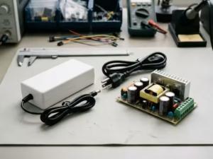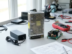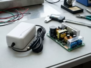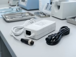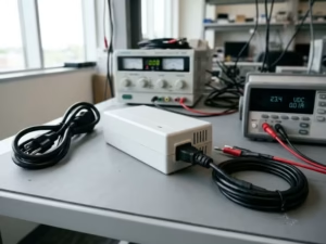
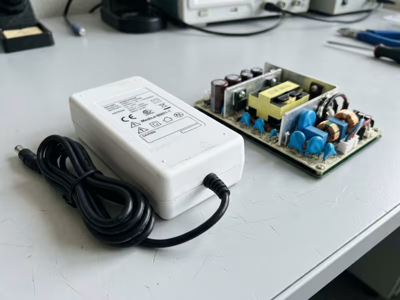
Many medical device teams face a costly redesign late in a project. The cause often goes back to one early choice: 1 MOPP or 2 MOPP.
This isn’t just a certification label. It shapes your transformer, PCB layout, leakage current budget, BOM cost, and launch date. Get it wrong, and you often have to redo the magnetics and the board.
I have helped many device teams make this decision early. Most of the rework I see starts when teams treat isolation as something to confirm later. This guide shows you when 1 MOPP fits, when you need 2 MOPP, and how to avoid late-stage rework in medical power supply design.
Why the 1 MOPP vs 2 MOPP Choice Matters Early
Many teams treat isolation as a box to tick during certification. They pick a power architecture, finish the layout, and plan to “confirm MOPP with the lab later.” By then, the hardware already locks in the decision.
The isolation level drives almost every physical choice in the power path:
- Transformer construction. It sets how you wind and insulate the transformer.
- Creepage and clearance. It sets the distances across the primary-to-secondary barrier.
- Leakage current budget. It limits how much Y-capacitance you can use for EMC filtering.
- PCB spacing. It controls slot placement, keep-out zones, and optocoupler size.
- Enclosure size and BOM cost. All of the changes above push on both.
The gap between the two levels is large. At 230 VAC mains, 1 MOPP typically calls for about 4 mm of creepage and a 1,500 VAC test. 2 MOPP roughly doubles the creepage to about 8 mm and raises the test to 4,000 VAC. Moving from 1 MOPP to 2 MOPP is not a component swap. It changes the transformer and the board.
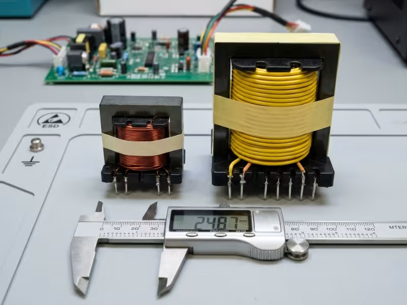
Here is why the change spreads so far. A 2 MOPP transformer usually needs triple-insulated wire or extra insulation layers, wider margins, and often a different bobbin. That can mean a larger core and a taller part. The wider spacing needs more board area, so nearby parts have to move. You may also need wide-body optocouplers or new digital isolators. Each change reopens your EMC results and your safety file.
I watched one team go through this with a portable patient monitor. They designed the supply for 1 MOPP and sent samples to the lab. During the review, the lab traced a conductive path from mains to the patient sensor that needed 2 MOPP. The transformer had to grow, and the board grew with it. The new board no longer fit the molded housing. The team redid the magnetics, layout, and enclosure, then rebooked lab time. They lost about three months.
That team didn’t make a bad engineering choice. They made it too late. If you settle the MOPP level before schematic capture, the transformer, layout, and enclosure grow around the right constraints from the start. If you settle it after layout, you pay to build the design twice.
What 1 MOPP and 2 MOPP Actually Mean
You don’t need to memorize IEC 60601-1 to make this call. You need to know three things: what MOPP protects, why its rules are stricter than other safety rules, and what changes when you go from one barrier to two.
Start with who the protection is for.
MOPP vs MOOP: Why Patients Get Stricter Rules
MOPP stands for Means of Patient Protection. It covers any barrier, such as insulation, spacing, or a protective earth, that keeps hazardous current away from the patient. IEC 60601-1 also defines MOOP, or Means of Operator Protection, for the nurse or user who runs the device.
The patient gets the tougher standard for a simple reason. An operator can feel a shock and pull away. A patient may be sedated, asleep, or connected through gel electrodes on damaged skin. They often can’t react, and their body resistance may be much lower.
The numbers show the gap. At 250 VAC, 1 MOOP and 1 MOPP both use a 1,500 VAC test. But 1 MOOP needs about 2.5 mm of creepage, while 1 MOPP needs about 4 mm. A supply designed only for operator safety often falls short once a patient enters the circuit.
1 MOPP vs 2 MOPP in Plain Terms
The number tells you how many independent protection layers sit between mains and the patient. Here is what changes when you add the second one:
- Protection level. 1 MOPP gives one layer. 2 MOPP gives two, so the patient stays safe even if one fails.
- Insulation strength. 1 MOPP usually means basic insulation. 2 MOPP means double or reinforced insulation.
- Spacing. Creepage rises from about 4 mm to about 8 mm, and clearance from about 2.5 mm to about 5 mm.
- Test voltage. The dielectric test jumps from 1,500 VAC to 4,000 VAC.
Treat these figures as a starting point, not a design target. Exact values depend on working voltage, pollution degree, and material group, so always confirm them in the IEC 60601-1 insulation tables.
The real question isn’t which level is “better.” It’s which level your device’s patient connection actually requires.
1 MOPP vs 2 MOPP: The Real Design Differences
On paper, the gap between 1 MOPP and 2 MOPP looks like a few numbers in a table. On the bench, it changes how you build almost every part of the power path. I tell clients to judge the two levels by what they do to the board, not by the test voltage alone.
The table below shows typical values at 250 VAC working voltage, with the design cost behind each one.
Feature | 1 MOPP | 2 MOPP | Design Impact |
|---|---|---|---|
Protection layers | One | Two independent layers | No single insulation fault can reach the patient |
Insulation type | Basic | Double or reinforced | Changes transformer build and isolator choice |
Creepage | ~4 mm | ~8 mm | Larger board area, slots, wider spacing |
Clearance | ~2.5 mm | ~5 mm | Taller parts, greater air gaps |
Dielectric test | 1,500 VAC | 4,000 VAC | Stronger insulation materials, tighter process control |
Bridging Y-capacitor | Y2 class | Y1, or two Y2 in series | Less usable capacitance for EMC filtering |
Isolators | Standard packages | Wide-body, reinforced-rated parts | Higher BOM cost, fewer part choices |
Here is what each of those rows means once you start laying out real hardware.
Clearance and Creepage: Where Board Space Disappears
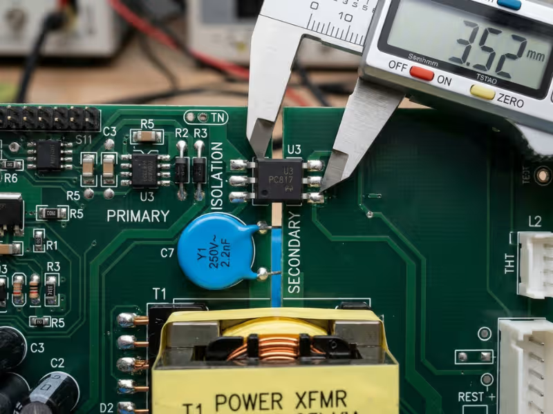
Doubling creepage from 4 mm to 8 mm sounds small. On a compact 60 W board, it often decides the whole floor plan. Every trace, pad, and component on the primary side must stay 8 mm from the secondary side along the surface. That keep-out band cuts across the board and pushes parts outward.
Magnetics feel it most. The transformer must hold that spacing between windings and at the pins. That often means wider margin tape, a larger bobbin, or a pin layout that spreads primary and secondary pins apart. Routed slots under the transformer can help, but they only count if they meet the standard’s width rules.
Dielectric Strength: Two Routes to 2 MOPP
A 1 MOPP barrier must survive 1,500 VAC. A 2 MOPP barrier must survive 4,000 VAC. You can reach 2 MOPP in two ways.
Double insulation stacks basic and supplementary insulation, which you can test separately. Reinforced insulation is a single system that gives the same protection and passes the full 4,000 VAC test.
Most compact transformers use reinforced insulation, often with triple-insulated wire. That wire saves space, but it costs more and is harder to wind than standard magnet wire.
Leakage Current and EMC: The Trade-Off Most Teams Miss
This part surprises engineers. Higher patient protection can make EMC harder, not easier.
Your supply needs a Y-capacitor across the barrier to control common-mode noise. That capacitor also creates a leakage path toward the patient. At 264 VAC and 60 Hz, a 10 µA CF limit allows only about 100 pF in total. A 100 µA BF limit allows roughly 1 nF. A 2 MOPP barrier also needs a Y1 part or two Y2 parts in series, and the series option halves your effective capacitance.
The result is less filtering at the exact point where you need it most. Your engineers then lean on common-mode chokes, shielded windings, and careful layout to pass emissions.
Size, Cost, and Layout: How It Adds Up
These changes compound. A larger transformer raises board height. Wide-body optocouplers or reinforced digital isolators add cost and shrink your second-source options. Wider spacing and a taller profile put pressure on the enclosure, especially in handheld or slim designs.
The hidden cost shows up in prototypes. Each spacing or filtering change can trigger a new layout, new samples, and a new EMC pre-scan. On 2 MOPP projects, I plan for at least one extra prototype round unless the team starts from a proven platform.
When 1 MOPP Is Usually Enough
Some teams treat 1 MOPP as a shortcut. It isn’t. In the right architecture, 1 MOPP is a sound design choice that you can test and defend in front of a lab.
The word that matters is architecture. IEC 60601-1 looks at the total protection between mains and the patient. One power supply is only part of that picture.
Three Setups Where 1 MOPP Holds Up
These are the setups where I see 1 MOPP hold up in real projects:
- The device adds its own patient isolation. Many monitors place an isolated front end between the main board and the sensor. If that barrier provides one MOPP, the power supply may only need to provide the other. Together, the two layers reach 2 MOPP from mains to patient.
- Protective earth carries part of the load. In a Class I design, an earthed shield or earthed secondary can count as one means of protection. Basic insulation on top of it may complete the job. You need a reliable earth path, and the lab will check it closely.
- Low working voltage and low-risk contact. Some barriers sit between a low-voltage secondary rail and a Type B or BF part, such as a skin-surface sensor. These barriers often see only a few volts. At that level, 1 MOPP spacing stays small and easy to meet.
In all three cases, the patient contact is non-cardiac. If an applied part can reach the heart, you need a different answer.
Why “Type BF” Doesn’t Settle the Question
Many engineers assume BF means 1 MOPP and CF means 2 MOPP. That shortcut causes trouble. BF tells you the applied part floats and sets a 100 µA patient leakage limit. It doesn’t tell you how many barriers sit between mains and the patient, or where they sit.
Here’s a case I see often. Two BF devices use similar sensors. The first has an isolated front end, so a 1 MOPP adapter works. The second wires the sensor straight to the adapter’s DC output. That adapter must provide the full 2 MOPP by itself.
So ask two questions. What working voltage does the barrier actually see? Which other barriers already protect the patient?
Then write the answer down. Draw a simple isolation diagram and mark each barrier with its MOPP rating and working voltage. Record the reasoning in your ISO 14971 risk file. Walk your test lab through it before you freeze the layout.
If the lab agrees early, you can defend 1 MOPP as a design choice. If it doesn’t, you find out while changes still cost very little.
When 2 MOPP Is Required or the Safer Choice
If 1 MOPP depends on the right architecture, 2 MOPP depends on the right risk. Some devices leave you no real choice. Others leave room to argue, but the argument may not be worth it.
Let’s start with the cases where the patient connection decides for you.
Cases Where 2 MOPP Isn’t Up for Debate
Cardiac (Type CF) applied parts. If any part can reach the heart, treat 2 MOPP from mains to patient as mandatory. CF allows only 10 µA of patient leakage in normal conditions. A single layer of insulation leaves no safety net if it fails. Labs review CF designs closely, and I have never seen a CF project pass with a “1 MOPP is enough” argument on the power path.
Direct conductive patient connections. Some designs wire the patient circuit straight to the supply’s DC output, with no isolated front end in between. Examples include ECG leads, conductive electrodes, and some therapy probes. In these designs, the power supply is the only barrier between mains and the patient. It must provide the full 2 MOPP by itself.
Higher working voltage across the barrier. The familiar 8 mm creepage and 4,000 VAC test assume about 250 VAC. Some barriers see more, such as the high-voltage bus after a PFC stage or the output side of a high-voltage therapy circuit. As working voltage rises, spacing and test voltage climb further. A barrier that barely passes at 250 VAC often fails once you apply the real working voltage.
Home-use devices. IEC 60601-1-11 assumes lay users and unknown wiring. Many homes have outlets with no reliable earth. That pushes most home-use adapters toward a Class II design, which can’t rely on protective earth. With no earth to share the load, the supply itself must deliver 2 MOPP.
Those are the forced cases. The harder question comes when the standard leaves room for 1 MOPP.

When I Default to 2 MOPP Anyway
On many power supply projects, I start the evaluation at 2 MOPP, even when 1 MOPP looks arguable. Here is why.
The end architecture is unclear. A power designer often doesn’t control the full device. Your customer may add a direct sensor connection later or remove the isolated front end to cut cost. A 2 MOPP supply survives those changes. A 1 MOPP supply may not.
One supply serves many devices. A 2 MOPP external adapter can support B, BF, and many CF programs with the same certified design. That turns it into a reusable platform instead of a one-off, which is one reason many teams evaluate custom power adapter solutions early.
The lab review gets simpler. A 1 MOPP case depends on a system-level argument about earth paths and other barriers. A 2 MOPP supply stands on its own. Reviewers ask fewer questions, and you spend less time defending the design.
The cost gap is smaller than the risk. Going to 2 MOPP usually adds some board area, a reinforced transformer, and wider isolators. That raises unit cost. A late switch from 1 MOPP to 2 MOPP can cost a new transformer, a new layout, and months of retesting.
2 MOPP isn’t free. It tightens your leakage budget and makes EMC filtering harder. But if 1 MOPP holds up only because of a careful system argument, I usually choose 2 MOPP and design around those trade-offs from day one.
How to Decide: A Practical 5-Step Framework
Most teams that pick the wrong MOPP level did not misread the standard. They skipped a step, or did the steps out of order. When I help a team make this call, I use the same five steps every time, and I finish them before anyone opens the schematic tool.
Work through these in order. Each step depends on the one before it.
Step 1: Classify the Applied Part Correctly
Start with the patient contact, not the power supply. Decide whether each applied part is Type B, BF, or CF, based on how and where it touches the patient.
Three mistakes come up again and again:
- Missing hidden applied parts. IEC 60601-1 treats parts that may touch the patient as applied parts too. A handle, a probe housing, or a cable a patient rests on can all count.
- Classifying for the main use only. If clinicians might use your device during cardiac procedures, even occasionally, plan for CF.
- Treating BF as the answer. BF sets a 100 µA leakage limit. It does not tell you how many barriers you need. The steps below decide that.
Your output: A list of every applied part, with its type and a one-line reason for that type.
Step 2: Find the Real Working Voltage Across the Barrier
Many engineers write “230 VAC” and move on. That number describes the mains, not what your barrier actually sees.
In a flyback supply, the primary switch node can ring to 500–600 V peak at high line. The voltage across the transformer’s primary-to-secondary barrier can exceed the mains RMS value. After a PFC stage, the bulk bus often sits near 400 VDC. High-voltage therapy outputs can go higher still.
Measure or simulate the worst case at maximum input voltage. Record both the RMS and peak values. The insulation tables use both, and the higher one usually sets your spacing.
Your output: The working voltage, RMS and peak, for every barrier on your isolation diagram.
Step 3: Trace the Patient Contact Path and Fault Scenarios
Now draw the path from the AC inlet to every patient contact point. Mark each barrier along the way: transformer, isolated front end, optocouplers, and protective earth.
Then apply single-fault thinking. Assume one barrier fails. Ask what still stands between mains and the patient. If nothing does, that path needs more protection.
Check these points closely:
- Conductive contact. Electrodes, ECG leads, and metal probes create a direct path for current.
- Cardiac relevance. Any path that can reach the heart demands 2 MOPP from mains to patient.
- Signal ports. A USB or Ethernet link to a non-medical PC can bring a second mains-referenced path into the device. Teams often forget it.
- Earth reliability. In a Class I design, ask whether the earth path stays sound in real use, especially at home.
Your output: A one-page isolation diagram, with each barrier marked by MOPP count and working voltage.
Step 4: Check the Insulation Tables Before You Lock the Architecture
With working voltages in hand, open the MOPP table in IEC 60601-1, which is Table 12 in the third edition. Read the creepage, clearance, and test voltage for each barrier.
Apply the right conditions. Most medical supplies use pollution degree 2. Your PCB material group, set by its CTI rating, changes the creepage values. If you sell in regions above 2,000 m, apply the altitude correction to clearance.
Do this before schematic capture. At that point, you can still choose a bigger bobbin, a wide-body optocoupler, or a routed slot at no extra cost. After layout, each of those choices means a respin.
Your output: A short spacing table listing each barrier, its required creepage and clearance, and its test voltage. Give it to your layout engineer on day one.
Step 5: Confirm With the Lab Early and Document the Rationale
Book a short review with your test lab or notified body before you freeze the design. Bring your applied part list, isolation diagram, and spacing table. Ask one direct question: “Do you agree with our MOPP count on each barrier?”
Ask for the answer in writing. An email is enough. Lab reviewers sometimes change, and a written agreement saves you from re-arguing the case later.
Then record the decision in your ISO 14971 risk file. Link each MOPP choice to the hazard it controls and the evidence behind it. If you later change the device, such as removing an isolated front end to cut cost, the file shows exactly which choice you need to revisit.
Your output: Written lab agreement and an updated risk file entry.
Once you finish these five steps, you have a defensible choice and a design team building around the right constraints from the start.
Where Teams Get This Decision Wrong
Most MOPP mistakes don’t come from weak engineering. They come from reasonable shortcuts taken under schedule pressure. I see the same five errors across monitors, therapy devices, and home-care products, and each one has a clear cost.
1. Misclassifying the Applied Part
A team designs a handheld ultrasound probe and lists only the transducer face as an applied part. The lab points out that the grip also rests against the patient during scans. Now a second contact path needs review.
Other teams see “Type BF” on the spec and assume 1 MOPP follows. BF sets the leakage limit. It says nothing about how many barriers you need or where they sit.
2. Planning to “Upgrade to 2 MOPP Later”
This sounds sensible when the end market is still unclear. In practice, there is no simple upgrade path.
Going from 1 MOPP to 2 MOPP means a reinforced transformer, roughly double the creepage, wider isolators, and often a new bobbin. The board grows, and the housing may no longer fit. Your EMC data and safety file also reopen. If there’s a real chance you’ll need 2 MOPP, design for it now.
3. Reading the Tables at Mains Voltage
An engineer looks up spacing at 250 VAC and lays out the board. Later, the lab measures the transformer barrier and finds peaks well above that from flyback ringing at high line. The required creepage climbs past what the layout allows, and the fix is a respin.
Always measure the worst-case RMS and peak working voltage across each barrier. Then read the tables.
4. Solving Isolation and Forgetting Leakage
A team meets 2 MOPP spacing cleanly, then fails conducted emissions. Their first instinct is to add Y-capacitance. But a CF design at 264 VAC can carry only about 100 pF across the barrier before it breaks the 10 µA limit.
Every picofarad that helps EMC hurts leakage. Plan your common-mode chokes, shielded windings, and filter budget when you set the isolation level, not after the first EMC failure.
5. Calling the Lab After the Design Is Done
This one costs the most time. A team finishes layout, builds samples, and sends a full test package. The reviewer disagrees with one barrier rating, and every downstream choice shifts with it.
A one-hour review before schematic capture would have caught the issue. Instead, the team waits weeks for a new lab slot after the fix.
These mistakes share one thread. Each team treated the MOPP level as a detail to confirm, not a decision to make. When you settle classification, working voltage, leakage budget, and lab agreement first, the hardware grows around the right constraints, and the rework never starts.
Can One Component Provide 2 MOPP?
Yes, sometimes. A transformer with reinforced insulation can provide 2 MOPP across its barrier by itself. So can a digital isolator or optocoupler that carries a reinforced rating under IEC 60601-1. Engineers ask me this often, and the honest answer is “yes, but only under the right conditions.”
Start with the rating itself. A datasheet line that says “2 MOPP” usually comes with limits. The part may qualify only up to a set working voltage, often 250 VRMS. It may also assume a certain pollution degree or altitude. If your barrier sees 400 V peaks from flyback ringing, a part rated at 250 VRMS may no longer qualify.
Next, look past the part to the board around it. A wide-body isolator may offer 8 mm between its pins, but your layout can still undo that gap. A trace, a via, or a stray solder pad can cut the creepage path. A Y-capacitor or heatsink can bridge the barrier too. Your feedback loop may also cross the barrier through a second part. The component meets 2 MOPP. Your system may not.
Then check the paperwork. Your safety file must name the exact part number and its certification, and your supplier’s production and testing facilities should hold that level of control in mass production. If purchasing swaps in a “same spec” alternative, the lab will treat it as a change.
My advice is simple. Before you commit to any single-component barrier, ask the supplier for its CB or TÜV report, not just the datasheet. Confirm that the certified working voltage covers your worst-case RMS and peak values. Then check the layout around the part with the same care.

FAQs About 1 MOPP vs 2 MOPP
These are the questions device teams ask me most often when they start this decision.
What does MOPP stand for in medical devices?
MOPP stands for Means of Patient Protection. IEC 60601-1 uses the term for any safeguard that keeps hazardous voltage and current away from the patient, including insulation, creepage and clearance distances, and protective earth.
You count MOPP for each barrier. One MOPP gives one layer of protection. Two MOPP gives two independent layers, or one reinforced layer, so the patient stays safe if one fails.
Is 2 MOPP always better than 1 MOPP?
No. 2 MOPP gives more protection, but it costs board space, transformer size, and leakage budget. It also limits Y-capacitance, which makes EMC filtering harder.
If your device already has an isolated front end or a reliable earth path, 1 MOPP on the supply can be the right call. Choose the level your patient connection requires, and default to 2 MOPP when the final architecture is still unclear.
What is the difference between MOPP and MOOP?
MOOP protects operators, such as nurses and technicians. MOPP protects patients, who may be sedated, connected through electrodes, or unable to pull away from a shock.
At 250 VAC, both use a 1,500 VAC test for one means of protection. But 1 MOOP needs about 2.5 mm of creepage, while 1 MOPP needs about 4 mm.
How many MOPP does a Type BF device need?
The BF label alone doesn’t answer this. BF sets a 100 µA patient leakage limit, but it doesn’t tell you how many barriers sit between mains and the patient.
Most designs need 2 MOPP in total along that path. If an isolated front end provides one MOPP, the supply may only need to provide the other. If the sensor connects straight to the DC output, the supply must provide both.
Can a single component provide 2 MOPP?
Yes, under the right conditions. A reinforced-insulation transformer, digital isolator, or optocoupler can provide 2 MOPP by itself.
Check its certified working voltage, often 250 VRMS, against your worst-case RMS and peak values. Then check the layout, because a trace, via, or Y-capacitor can bridge the gap. Ask for the CB or TÜV report, not just the datasheet.
Does IEC 60601-1 specify exact creepage distances?
Yes, but not as one fixed number. The standard lists minimum creepage and clearance for MOPP in Table 12 of the third edition. Those values change with working voltage, pollution degree, and PCB material group. Above 2,000 m, clearance also needs an altitude correction.
The common figures of about 4 mm and 8 mm assume roughly 250 VAC. Measure your real working voltage first, then read the table.
Make the MOPP Call Before You Draw the First Trace
Teams rarely lose months on MOPP because they misread a number in the standard. They lose them because they made the call after the transformer, layout, and housing already existed. By then, the isolation level isn’t a choice anymore. It’s a constraint you have to rebuild around.
Treat 1 MOPP and 2 MOPP as architecture decisions. They set your transformer build, your spacing, your leakage budget, and your EMC strategy. A lab report should confirm that choice, not make it for you.
Settle three things before anyone opens the schematic tool. First, classify every applied part, including the ones a patient might touch only by accident. Second, measure the worst-case RMS and peak working voltage across each barrier. Third, meet with your test lab and get written agreement on the MOPP count for each path.
That meeting takes about an hour. Skipping it can cost you a full redesign.