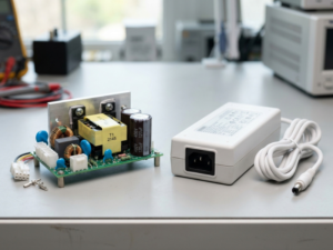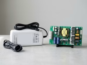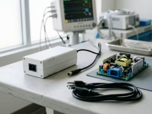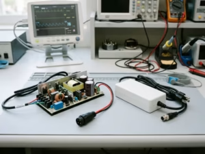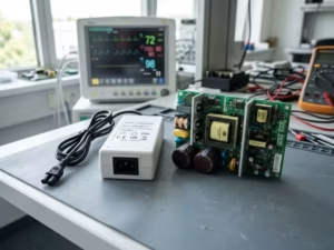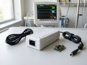
This Is Not Just a Packaging Choice
Many engineers treat external vs internal medical power supplies as a packaging question. It is not. Where mains power enters your device shapes almost every decision that follows.
I see the same pattern on project after project. A team picks a power architecture early, almost casually. Months later, that choice drives their test plan, their enclosure, and their budget.
Here is what this one decision touches:
- Safety isolation strategy: how you separate the patient from mains voltage
- IEC 60601-1 certification path: how much testing and documentation your full system needs
- Thermal and enclosure design: where the heat goes and how big the box gets
- Maintenance approach: whether users swap a part or you handle the repair
- Long-term cost and supply chain: what you pay, and what you risk, over the product’s life
Get it right, and your project moves faster. Get it wrong, and you may redesign the enclosure or repeat safety tests late in development.
This article won’t give you a theory lesson. It gives you a clear way to decide. We’ll walk through the real tradeoffs between safety, power, size, timeline, and cost. By the end, you’ll know which architecture fits your device and why.
External vs Internal Medical Power Supplies: The Real Difference
Most comparisons start with shape and size. That misses the point. Let’s define each option, but only the parts that change your decision.
What Is an External Medical Power Supply?
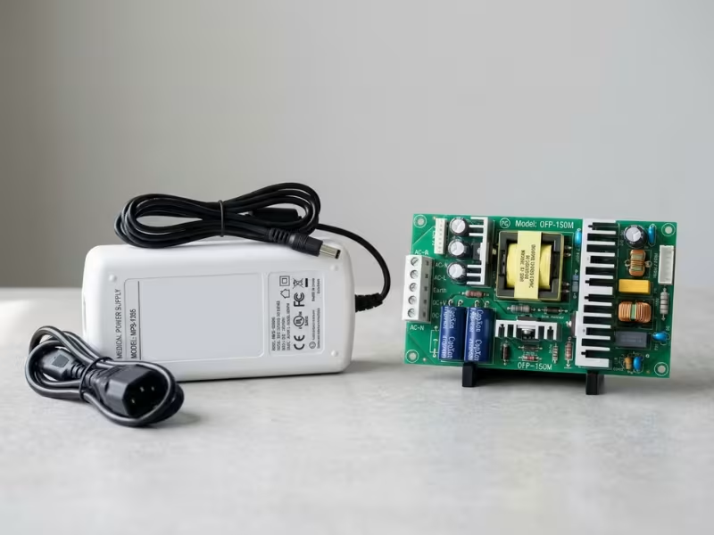
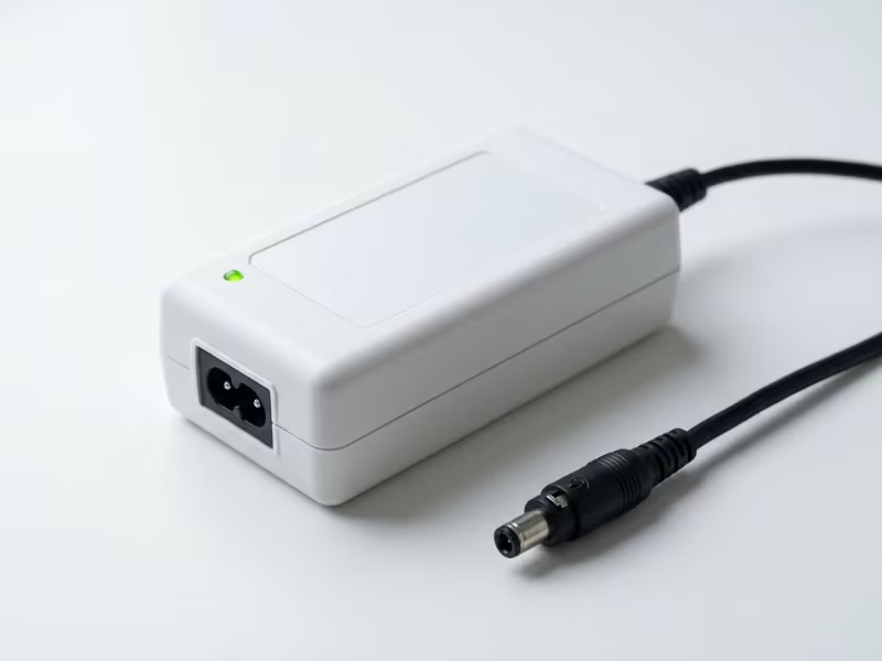
An external supply sits outside your device. It usually takes the form of a wall adapter or a desktop brick.
The AC-DC conversion happens inside that adapter. Your device only receives low-voltage DC, commonly 12 V, 19 V, or 24 V.
Many catalog adapters already carry their own medical approval, and plenty of 2x MOPP versions are available off the shelf. That gives you a tested, documented safety barrier before power ever reaches your product. If you want to compare typical form factors, isolation ratings, and output ranges, you can review these medical power supplies.
What Is an Internal Medical Power Supply?
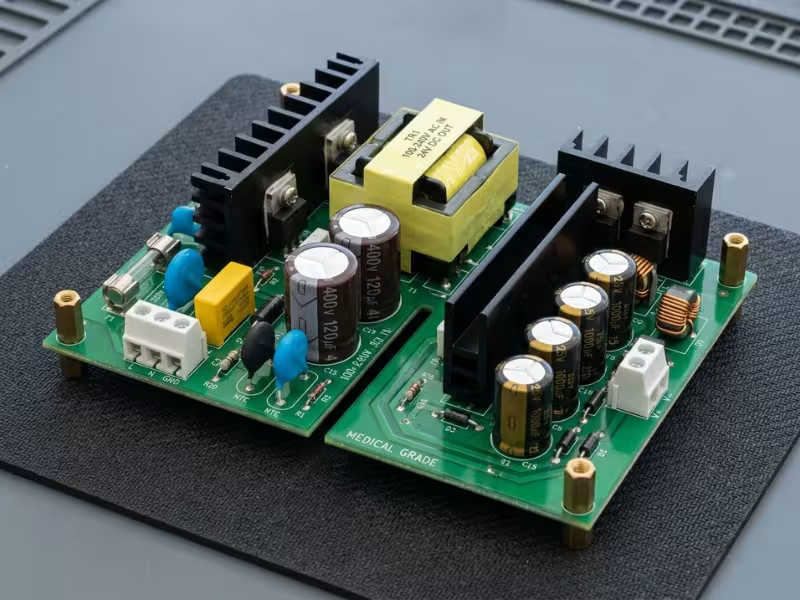
An internal supply lives inside your enclosure. It may be open-frame, enclosed, or U-channel. The exact style often matters less than teams expect.
With this setup, AC mains enters your device directly. The power supply becomes one component in a larger system.
That shifts more work to your team. You own the wiring, spacing, grounding, and enclosure design around it. You also own more of the testing.
The Difference That Actually Matters
So far, these sound like simple packaging options. They are not. Here is how I explain it to clients.
An external architecture moves the mains boundary outside the device. Hazardous voltage stays in the adapter. Your product starts life on the safe side of the fence.
An internal architecture brings mains, heat, and compliance responsibility inside your box. Every millimeter near the input now carries safety weight.
So the real distinction isn’t form factor. It’s where the mains boundary sits, and who carries system responsibility for it. Once you see it this way, every later tradeoff gets easier to judge. Safety, thermal design, cost, and service all trace back to this one line.
Start Here: 5 Questions That Decide the Architecture
Before you compare datasheets, answer five questions. I ask clients these in our first meeting. In many cases, the answers point toward one architecture within an hour.
Each question links to a deeper topic later in this article. Use this list as your map.
1. Does the Device Touch the Patient, and What Isolation Does It Need?
Start with applied parts. If your device has Type BF or CF parts, or sits within reach of the patient, you will likely need 2x MOPP between mains and the patient. An external 2x MOPP adapter can carry much of that burden for you. An internal supply can do it too, but your enclosure, spacing, and grounding must prove it.
2. How Much Continuous and Peak Power Does It Need?
Look at the real load profile, not the nameplate. As a practical rule of thumb, external adapters below roughly 100–150 W are easy to source and easy to handle. Above about 250 W, or with motors and pumps that can pull two to three times their running current at startup, internal supplies often become the more practical choice. Don’t forget battery charging, which can quietly push your peak much higher.
3. Can the Enclosure Absorb the Heat?
A 200 W supply running at 90% efficiency still releases more than 20 W of heat inside your box. Ask whether you have room for airflow, and whether a fan is even acceptable. Sealed plastic housings and quiet bedside units often struggle with that load. If the answer is no, the heat probably belongs outside, in an adapter.
4. How Fast Do You Need to Pass Compliance and Launch?
Be honest about your timeline. A pre-certified external adapter can take a large share of mains-side testing off your system review. An internal design adds work on creepage, leakage, dielectric strength, and wiring. One failed test can push your lab date back by weeks, so fixed launch dates should weigh heavily here.
5. Will It Ship Globally and Stay on the Market for Years?
Selling in several regions with an external adapter can mean multiple plug types, cords, labels, and SKUs. An internal supply with an IEC inlet keeps that simpler, but it ties you to one part for the product’s whole life. Many medical devices stay on the market for 7–10 years, which can outlast a typical power supply model. Plan your second sources now, not after your first last-time-buy notice.
How to Read Your Answers
If most answers lean the same way, you have a strong starting point. If they split, such as high power with a tight launch window, a hybrid design often fits best.
Let’s unpack each question in detail, starting with the one that carries the most weight: safety and compliance.
Safety and Compliance: Where External Usually Has the Advantage
Test labs care about this part of the decision more than any other. It’s also where the mains boundary stops being a concept and starts costing real time and money.
Three areas show the difference most clearly: the standard itself, isolation, and leakage current.
How IEC 60601-1 Shifts With the Mains Entry Point
An external medical adapter brings its own certification to the table. It typically arrives with a CB report and test data for the mains side. Your lab can review that file instead of retesting the adapter’s insulation from scratch.
Your device then sits on the low-voltage DC side. That can shrink the mains-side questions considerably, though not to zero.
An internal supply works differently. Even a fully approved component only proves that the power supply passed on its own. It doesn’t prove your system passes.
The certificate usually comes with conditions of acceptability. These spell out mounting, spacing, airflow, and grounding rules. Break one, and the approval may no longer cover your build.
Your team still owns the system-level checks:
- Leakage current with the supply installed
- Dielectric strength across the full product
- Creepage and clearance around the inlet, fuse, and switch
- Internal wire routing and insulation
- Enclosure strength, openings, and fire protection
I’ve watched teams pick a “fully certified” internal module and assume they had finished the hard part. Then the lab flagged a harness running too close to a primary-side heatsink. That meant a redesign and a second test slot.
MOPP, Applied Parts, and Your Isolation Plan
Think of a MOPP (Means of Patient Protection) as one layer of safety between mains and the patient. 1x MOPP gives you one layer. 2x MOPP gives you two, so if one fails, the patient stays protected.
The numbers make the gap clear. At a typical 250 VAC working voltage, 1x MOPP calls for about 1,500 VAC isolation and 4 mm creepage. 2x MOPP calls for about 4,000 VAC and 8 mm. Exact values depend on working voltage and insulation type, so always confirm against the standard’s tables.
That jump matters when your device has applied parts. Type BF parts contact the patient, like ECG electrodes or blood pressure cuffs. Type CF parts can contact the heart directly, so they face the strictest limits.
With a 2x MOPP external adapter, the toughest barrier lives in the adapter. Your device starts with low-voltage DC that already sits behind two layers. You still isolate applied parts as their type demands. But you no longer need to fit an 8 mm mains barrier inside a compact housing.
Internal designs can absolutely meet 2x MOPP. Many cart-based and imaging systems do it every day. The burden simply lands on you: transformer choice, PCB slots, barrier placement, and insulation coordination all need careful work.
My rule of thumb: if your team hasn’t built a 2x MOPP system before, an external adapter buys you margin while you learn.
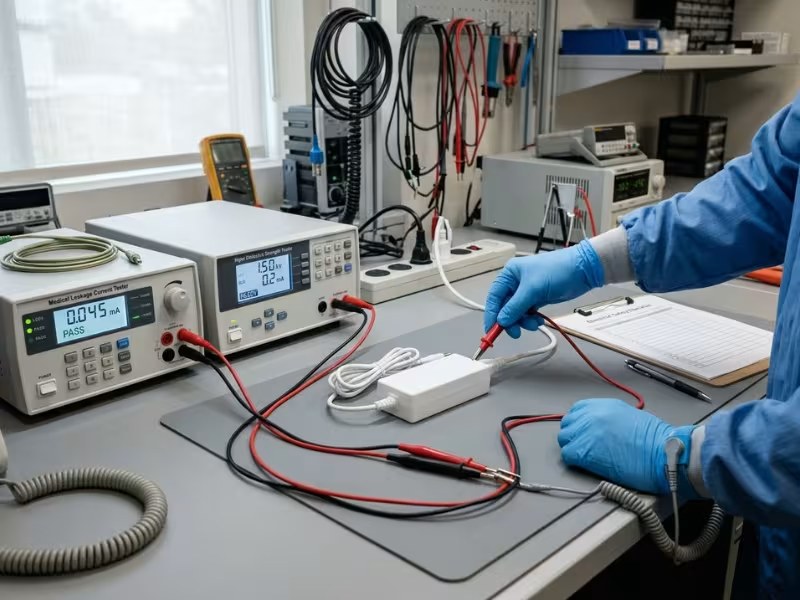
Leakage Current: Where Decisions Get Real
Leakage current is where paper plans meet the test bench. Three paths matter most.
Patient leakage flows through applied parts into the patient. Touch current flows from the enclosure through anyone who touches it. Earth leakage runs down the protective earth conductor.
Limits get tight fast. For CF applied parts, patient leakage must stay at or below 10 µA under normal conditions. Touch current is typically limited to 100 µA under normal conditions.
An external Class II adapter can help in two ways. It keeps mains-referenced circuitry physically outside your enclosure. It can also remove protective earth from your device, so earth leakage may drop off your list. Many medical adapters keep touch current well below the 100 µA limit.
Internal designs make several details more sensitive:
- Y capacitors: They tame EMI but push current toward earth. More capacitance generally means more leakage.
- Grounding: An open-earth fault can send that current through the enclosure, or the patient.
- Enclosure: Metal housings and chassis bonds add paths you must measure.
- Wiring: Harnesses near patient-connected circuits can couple current in.
This is why EMI filtering and leakage limits often fight each other inside the box. Fix one, and you can break the other.
Still, external is not an automatic pass. Cable routing, accessories, and your own DC-side circuits can still fail leakage or IEC 60601-1-2 EMC tests. You still need to verify the full system.
Here’s how the two paths compare at a glance:
Decision Factor | External Supply | Internal Supply |
|---|---|---|
Mains boundary | Outside the device | Inside the device |
Isolation burden on device | Lower | Higher |
Leakage current control difficulty | Usually lower | Usually higher |
Certification path | Often faster | Usually more involved |
Thermal, Mechanical, and EMC Tradeoffs Inside the Product
Safety decides whether you can ship. Heat, size, and electrical noise decide whether people actually like using what you ship. These problems tend to surface later in the project, but they all trace back to the same mains boundary.
Thermal Design: Send the Heat Out or Manage It In
Every power supply wastes some energy as heat. The real question is where that heat lands.
An external adapter keeps its losses outside your enclosure. A 60 W adapter at 90% efficiency sheds roughly 6–7 W into the room, not into your electronics. Your sensors, batteries, and display run cooler, and your housing can stay compact.
An internal supply adds a heat source right next to everything else. That creates a list of jobs your team now owns:
- Airflow: Plan a clear path from intake to exhaust. Cables and boards love to block it.
- Derating: Many open-frame supplies start derating around 50 °C ambient. Inside a closed box, local air often runs 10–15 °C above room temperature. In that case, a 150 W supply may only deliver around 100 W safely.
- Fans: A fan adds cost, a filter to clean, a part that wears out, and a new failure mode.
- Surface temperature: IEC 60601-1 limits how hot touchable surfaces can get. Those limits tighten for parts that stay against skin.
Noise deserves its own warning. A quiet bedroom often sits near 30 dBA. A fan running at 35 dBA can keep a home-care patient awake all night. Nurses also notice a whining unit at the bedside.
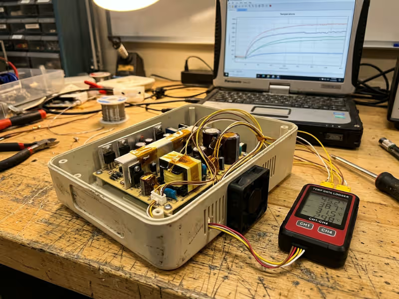
My advice: build a crude thermal mockup early. Put power resistors at the real dissipation inside a prototype enclosure and log temperatures for a few hours. One afternoon of data beats weeks of guessing.
Mechanical Design and Portability
Heat shapes the inside of the box. Size and handling shape how people live with it.
Portable, wearable, and sealed devices tend to lean toward external power. Pulling the AC inlet, fuse, and supply out of the product saves real volume and weight. It also removes openings, which helps with IP ratings and makes harsh disinfectant wipe-downs easier.
Benchtop, cart-based, and rack-mounted systems often lean the other way. They already have room and mounting points. A single IEC power cord also looks cleaner on a hospital cart than a brick zip-tied to a pole.
Don’t ignore the user experience of external bricks. Clinicians often complain about:
- Adapters dangling from outlets or tangling on the floor
- Cords that create trip hazards near beds
- Lost adapters, or the wrong one plugged in from another device
You can soften these issues. Use a locking or keyed DC connector, a right-angle plug, solid strain relief, and a clearly labeled adapter. Choose cord length on purpose, too. No single length fits every room.
EMC and Sensitive Analog Systems
Noise is the tradeoff teams most often discover too late. Where you put the switcher can matter as much as which one you buy.
An internal supply switches high currents at tens or hundreds of kilohertz. It sits centimeters away from your most sensitive circuits. Think of ECG front ends reading microvolt signals, SpO2 sensors, or Wi-Fi and Bluetooth radios. Switching harmonics can couple into all of them.
That proximity makes your layout work harder:
- Keep physical distance between the supply and the analog front end
- Add shielding or a grounded barrier where distance runs out
- Plan return paths and ground planes with care
- Balance EMI filtering against leakage, since extra Y capacitance raises leakage current
External placement moves the main noise source a full cable length away. That usually gives you a calmer starting point. It doesn’t make EMC disappear, though. The DC cable can act as an antenna, so you may still need a ferrite or common-mode choke at the input.
Remember that IEC 60601-1-2 judges the whole system, not the power supply alone. Emissions, immunity, and ESD testing all happen with your exact configuration. If you change adapter suppliers later, plan for a retest.
Run a pre-compliance scan as soon as you have a working prototype. A day at a pre-scan lab often reveals the trouble spots while your layout is still easy to change.
Cost, Service, and Supply Chain: The Part Most Teams Underestimate
Engineers usually settle the safety and thermal debates. Then purchasing, service, and operations teams live with the results for the next decade. Here’s how the choice looks from their side of the table.
Look Past the Power Supply Price Tag
A quote sheet can mislead you. As an illustration, an internal open-frame supply might cost $18 at volume, while a similar external medical adapter costs $28. On paper, internal wins by $10 a unit. That gap rarely survives a full project intact.
The internal path often adds costs that never appear on the power supply line:
- Enclosure changes: an AC inlet, fuse holder, switch, vents, and sometimes a metal shield or chassis bond, plus the tooling to build them
- Thermal work: fans, heatsinks, airflow testing, and derating that can push you to a larger, pricier supply
- Certification effort: mains-side creepage, dielectric, and leakage testing on the whole system. One failed round can cost $10,000–$30,000 and several weeks, depending on the lab and scope
- Service complexity: trained technicians, depot repairs, and post-repair safety checks
The external path has its own extras:
- Per-unit adapter cost: higher, and paid on every unit you ship
- Cable assemblies: DC cords, locking connectors, and regional AC cords
- Packaging space: a bigger box, plus labels and instructions for the adapter
Now run the math. At 2,000 units a year for five years, a $10 saving adds up to $100,000. If the internal route adds $60,000 in engineering and testing plus two months of delay, the real advantage shrinks fast. At something like 50,000 units a year, internal often pulls ahead.
Build a simple model with three inputs: one-time engineering cost, per-unit cost, and launch delay. It settles most budget arguments quickly.
Serviceability and Field Replacement
When an external adapter fails, you ship a new one. The user plugs it in, and the device can run again the same day. Nobody opens the product or touches a tool. Many hospitals simply keep a few spares in the biomed shop.
That matters because many power failures in the field are physical. Think dropped bricks, crushed cords, and bent connectors. External designs keep that damage in a cheap, swappable part.
An internal failure looks very different. The device goes back to a depot, or a technician opens it on site. After opening a medical device, teams usually repeat electrical safety checks, often under IEC 62353, before it returns to service. Add shipping, downtime, and loaner units, and a $20 part can trigger a service event costing hundreds of dollars.
Internal often wins in long-term, high-load use, though. Picture a cart-based system running 24/7 at 180 W. You can install a 300 W internal supply, run it near 60% load, and cool it with forced air. Electrolytic capacitors last far longer that way. As a common rule of thumb, their life roughly doubles for every 10 °C drop. A sealed adapter working hard at the bedside rarely gets that kind of headroom.
Internal power also ends lost and mixed-up adapters. For fleets with planned maintenance schedules, that predictability has real value.
Global Distribution and Lifecycle Risk
Shipping worldwide with an external adapter multiplies your parts list. You may need Type A for North America, Type C for Europe, Type G for the UK, Type I for Australia, and more. Each region brings its own cord, labels, instructions, and SKU.
You can tame this in two ways. Use an adapter with interchangeable clip-on plugs. Or choose a desktop adapter with an IEC C8 or C14 inlet, so one adapter pairs with many regional cords. If you need region-specific plugs, cord lengths, or locking connectors, custom power adapters can solve these details at the source instead of in your packaging. An internal supply with an IEC inlet keeps things simplest, since only the cord changes.
Catalog adapters bring a strong sourcing advantage. Common outputs like 12 V, 15 V, or 24 V, along with standard connectors, make it easier to qualify more than one vendor. Just remember that switching suppliers can still mean a risk-file update and an EMC retest.
Internal supplies tend to carry more lifecycle risk. Many are custom or semi-custom, with specific mounting holes and connector pinouts. During past component shortages, lead times stretched to 30 weeks or longer. End-of-life notices may give you only 6–12 months for a last-time buy. Replacing the part can mean re-verification and possibly a regulatory filing update.
Plan for this during design, not after the first warning letter:
- Qualify two candidates with matching output, footprint, and connector
- Design brackets and harnesses that fit both
- Ask vendors for lifecycle roadmaps and their change-notice policy
- Include both parts in your initial test report so the lab covers them together
- Set aside budget for a last-time buy
Here’s how these factors stack up side by side:
Cost or Ops Factor | External | Internal |
|---|---|---|
Upfront engineering effort | Lower | Higher |
Certification burden | Lower to moderate | Higher |
Field replacement | Easier | Harder |
Global SKU complexity | Higher | Lower to moderate |
High-volume cost potential | Sometimes worse | Often better |
Which Devices Usually Fit External vs Internal?
Theory only gets you so far. Most teams really want to know what products like theirs usually do. Here’s how the choice tends to play out across the device types I work with.
Treat these patterns as starting points, then test them against your five answers from earlier. You can also review typical application scenarios to see how similar devices handle power before you lock your design path.
External Usually Makes More Sense For
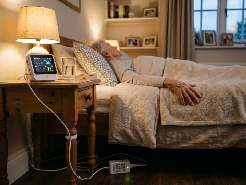
Home healthcare monitors top the list. Patients plug them into bedroom outlets you can’t control, sometimes without a reliable earth. A Class II adapter can reduce dependence on protective earth in the end-use environment. It also keeps heat and fan noise away from someone trying to sleep.
Portable diagnostic devices fit naturally too. Think handheld ultrasound, portable ECG recorders, or point-of-care analyzers. They often run on batteries most of the day, and the adapter mainly charges them. Leaving the AC stage behind saves weight in every carry.
Compact low-power systems, roughly under 100 W, benefit from a deep catalog. You can choose from many 2x MOPP adapters at common voltages, and many share standard connectors.
Sealed plastic enclosures strongly favor it. You avoid vents, an AC inlet, and a metal earth bond. That makes IP ratings and harsh disinfectant wipe-downs much easier to handle.
Fast-launch products round out the group. If your funding depends on a fixed submission date, a pre-certified adapter can pull much of the mains-side testing off your critical path. I’ve seen this alone save startups a full test cycle.
Internal Usually Makes More Sense For
Higher-power equipment shifts the balance quickly. Above roughly 250 W, external bricks tend to get heavy, hot, and awkward. Dialysis machines, surgical generators, and imaging systems also drive motors, pumps, or heaters with big startup surges. An internal supply with real derating headroom usually handles those peaks better.
Cart-based or stationary systems already have what internal power needs. Anesthesia workstations and ultrasound carts often come with metal chassis, protective earth, and space for airflow. A single IEC cord keeps the setup clean for clinical staff.
Systems needing tight internal rail control also lean internal. Some designs need power-good signals, rail sequencing, remote sense, or long hold-up times. Others need a smooth handover to backup batteries during a mains dropout. An internal supply puts all of that next to the load, where your firmware can watch it closely. Some even report status over PMBus.
Products with long lifecycles and service plans complete the list. If biomed teams will maintain your system for ten years, internal power fits their workflow. You can derate the supply, cool it with forced air, and replace it during scheduled service. No more lost adapters, either.
Hybrid Architectures Are Often the Practical Middle Ground
Many of the strongest designs I review don’t pick a side. They combine an external 2x MOPP brick with internal DC-DC conversion.
The adapter delivers a single safe rail, often 24 V. Inside the device, point-of-load converters build the 12 V, 5 V, and 3.3 V rails your electronics need. Isolated DC-DC modules can also create separate floating supplies for BF or CF applied parts.
This pattern shows up often for a simple reason. It keeps the mains boundary outside your enclosure, so certification stays lighter. Meanwhile, your team still controls rail quality, sequencing, and transient response right at the load.
You still need careful layout, because those DC-DC switchers make noise too. But you’re managing low-voltage noise, not mains hazards. For mid-power devices with demanding electronics, that trade frequently wins.
A Practical Selection Framework for Engineering Teams
If your team is stuck arguing external vs internal, you’re not alone. I walk into this debate all the time. The hardware lead wants internal for control. The program manager wants external for speed. Purchasing just wants a number.
The fix isn’t a longer meeting. It’s a fixed order of questions. Work through these five steps in sequence, and let each one narrow the field before you move on.
Step 1: Lock Down Patient Contact and Your Isolation Target
Start here, because nothing later can override it. List every applied part and its type: B, BF, or CF. Then write down the MOPP level you need between mains and the patient.
If the answer is 2x MOPP and your team has never built that barrier inside an enclosure, consider making external your default. Internal stays on the table, but now it has to earn its place.
Step 2: Set the Real Power and Thermal Budget
Pull actual load data, not the spec sheet target. Capture continuous draw, startup surges from motors or pumps, and battery charging at its worst moment. Many teams add 20–30% margin on top.
Next, use the efficiency figure to work out how many watts turn into heat. Then ask a blunt question: where will those watts go? If the enclosure has no airflow path and no room for a fan, the heat likely belongs in an adapter. If you need 300 W with surge headroom, internal often becomes the most practical choice.
Step 3: Compare Compliance Path and Launch Timeline
Sketch both certification paths side by side. For external, list what the adapter’s CB report already covers. For internal, list every mains-side test your lab will run: creepage, dielectric, leakage, wiring, and enclosure.
Then call your test lab and ask about real slot availability. Put a price on one failed round, in both dollars and weeks. If your launch date can’t move, that number often ends the debate on its own.
Step 4: Model Five-Year Cost and Sourcing Risk
Build a one-page model. Include engineering hours, tooling, certification, per-unit cost at your real volume, service events, and regional SKUs. Run it at low, expected, and high volume.
Then add a risk column. Can you name two qualified sources today? What happens if your supply hits end-of-life in year four? A cheaper design with one fragile source rarely stays cheaper.
Step 5: Prototype Both Critical Failure Points Early
By now, one option usually leads. Don’t trust it yet. Build quick tests for the two failure points that most often sink projects: leakage current and heat.
For leakage, wire up the candidate supply with your real Y capacitors, grounding scheme, and cable lengths. Then measure patient and touch current with a proper leakage tester. For heat, drop power resistors into a rough enclosure at the real dissipation and log temperatures for about four hours.
Here’s what I’ve learned from watching teams go through this. In many teams, the architecture decision is settled faster by early leakage and thermal pre-tests than by spreadsheet debates. A spreadsheet invites opinions. A thermocouple reading of 68 °C on a capacitor rated for 65 °C does not.
Both tests typically take a few days and a modest budget. Skipping them can cost you an enclosure redesign.
When the Steps Disagree
Sometimes Step 1 points external and Step 2 points internal. That split doesn’t mean the framework failed. It tells you to look hard at a hybrid: an external 2x MOPP brick feeding internal DC-DC stages.
Whatever you choose, write down which step drove the final call and why. Six months from now, someone will reopen the debate. That short note can save you a week.
Common Mistakes to Avoid
Most power architecture problems I see don’t come from bad engineering. They come from smart teams making one quick assumption early, then building on it for months. These four mistakes tend to cost the most time and money.
Assuming a cheaper adapter means a cheaper product. A low quote looks great in a design review. But the power supply price is only one line in a much bigger budget. A bargain adapter with thin leakage margins can fail your system test. A thin cord or weak strain relief can drive warranty returns. An internal supply that saves $10 a unit can quietly add vents, a fan, tooling changes, and an extra lab round. Compare total cost over five years, not the price of one part.
Treating a certified internal supply as a shortcut to full compliance. I hear this one constantly: “The module already has IEC 60601-1 approval, so we’re covered.” You’re not. That certificate proves the supply passed on its own, under specific mounting and spacing conditions. Your lab still tests leakage, dielectric strength, creepage, and wiring with the supply inside your box. Read the conditions of acceptability before layout starts, not after the first failed report.
Ignoring plug-region and SKU complexity until too late. Teams often design for one market, then learn sales wants Europe, the UK, and Australia next quarter. Suddenly one product becomes several SKUs, each with its own cord, labels, and packaging. Sort out your regional plan during concept design. Choose interchangeable plugs or an IEC inlet adapter early, and include every variant in your first test submission.
Postponing the architecture decision until after enclosure design. This is often the most expensive mistake on the list. Industrial design locks the housing, tooling gets quoted, and only then does someone ask where the power supply goes. If the answer is “inside,” you may need vents, an AC inlet, a metal shield, or more volume. If the answer is “outside,” you may need a new connector cutout. Either way, you risk paying twice.
The pattern behind all four is simple. Each one treats power as a component choice when it’s really a system decision. Settle the architecture before mechanical design hardens, and most of these problems disappear.
FAQ
These are the questions I hear most often in early design reviews. Each answer gives you the short version. The earlier sections cover the details.
What is the main difference between an external and internal medical power supply?
The real difference is where mains voltage enters. An external supply converts AC to DC outside your enclosure, so your device only receives low-voltage DC. An internal supply brings AC mains inside the box, along with its heat, spacing rules, and leakage risks.
Form factor is the part you see. The mains boundary is what shapes your isolation plan, test scope, thermal design, and service model.
Does an external medical adapter need its own IEC 60601-1 approval?
Your lab evaluates the adapter as part of your medical equipment, so it must meet IEC 60601-1 within your system. In practice, choose one that already carries medical approval and a CB report. That lets the lab review existing mains-side data instead of retesting the insulation from scratch.
For home-use products, also check IEC 60601-1-11 coverage. EMC testing under IEC 60601-1-2 still happens with your exact adapter and cable.
Can a standard ITE power supply be used in a medical device?
Sometimes, but rarely as a drop-in. ITE power supplies certified to IEC 62368-1 target operator protection, not patient protection. Their isolation and leakage limits are usually looser than medical requirements.
You can make one work with a medical-grade isolation transformer, extra downstream insulation, or placement outside the patient environment. Your risk file must justify it. After that added engineering, a purpose-built medical supply often costs less overall.
Which architecture makes 2x MOPP easier to achieve?
In many projects, external. A catalog 2x MOPP adapter already provides roughly 4,000 VAC isolation and 8 mm creepage between mains and its output. Your device starts behind that barrier.
You still isolate BF or CF applied parts as their type requires. Internal designs can meet 2x MOPP too, but your team owns transformer selection, PCB slotting, and insulation coordination. Without prior experience, external gives you margin.
When does an internal power supply become the better choice?
Internal often starts winning once loads pass roughly 250 W, or when motors, pumps, and heaters create large startup surges. It also suits cart-based and stationary systems that already have a metal chassis, protective earth, and room for airflow.
Long-lifecycle products with planned biomed service benefit too. If you need rail sequencing, power-good signals, or long hold-up times, internal keeps that control next to the load.
Can an external adapter and internal DC-DC stage be used together?
Yes, and it’s one of the most common designs I review. An external 2x MOPP adapter delivers a single safe rail, often 24 V. Internal DC-DC converters then build your 12 V, 5 V, and 3.3 V rails, and isolated modules can create floating supplies for applied parts.
This hybrid keeps mains outside your enclosure and certification lighter. Just lay out the internal switchers carefully, because they make noise too.
The Mains Boundary Comes First
External vs internal power is a system decision. Once you see it that way, most of the debate gets simpler.
External architecture usually lightens your load. It keeps mains, heat, and much of the certification burden outside your enclosure. A failed adapter also becomes a quick swap, not a service call.
Internal architecture earns its place in higher-power, longer-lifecycle, and more integrated systems. It gives you surge headroom, tight rail control, and a clean setup for planned biomed service.
Keep the decision order fixed: safety, then power and thermal, then timeline, then cost and risk, then prototype. Each step narrows the field before the next one starts.
My one piece of advice: run leakage and thermal pre-tests on your candidate architectures during the concept phase. Do it before industrial design locks the enclosure. A few days of bench data can settle the question faster than any meeting, and it costs far less than a redesign.
If you’re weighing external or internal power for a new medical device, bring your load profile, applied part types, and target markets to an early conversation with your power supply partner. Reviewing compliance needs and available medical-grade options at the concept stage keeps your choices open while changes are still cheap.