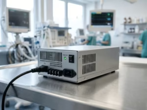
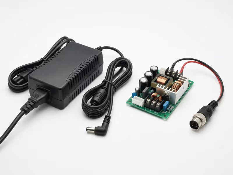
Specifying a medical power supply often comes down to one overlooked question: which isolation barrier protects the patient, and which protects only the operator? IEC 60601-1 addresses that distinction through MOPP (Means of Patient Protection) and MOOP (Means of Operator Protection). The difference is not just terminology — it directly affects creepage, clearance, dielectric strength, and leakage current, and ultimately whether your design is correctly specified for patient risk.
This guide explains MOPP vs. MOOP in practical specification terms: when MOPP is typically required, when MOOP may be sufficient, and exactly what engineers and buyers should verify in a datasheet or supplier discussion before trusting a “medical-grade” label.
MOPP and MOOP in Plain Specification Terms
Both MOPP and MOOP are types of MOP — a Means of Protection against electric shock. The acronyms differ by one letter, and that letter determines whether the protection is evaluated for patient or operator exposure conditions.
MOOP relates to operator protection. It applies to isolation barriers that stand between hazardous voltage and the person operating the device. That person is typically conscious, on a normal floor, and able to let go if something goes wrong. The protection requirements often resemble those of standard information-technology or industrial equipment.
MOPP relates to patient protection. It applies wherever an isolation barrier guards a path that can reach a patient — often through an applied part in contact with the body. A patient cannot be assumed to react. They may be anesthetized, connected to multiple grounded devices, or wired to a catheter that can carry current toward the heart. Because the worst-case victim is far more vulnerable, MOPP generally demands larger isolation distances, higher dielectric withstand, and much tighter leakage limits than MOOP at the same working voltage.
The practical takeaway: classification follows the person the barrier protects and the isolation path involved, not the product label. A single device frequently needs both — MOPP on the patient-connected path, MOOP on barriers that only touch the operator.
Side-by-Side Comparison: MOPP vs. MOOP
The table below summarizes how the two classes tend to diverge at the same working voltage. Treat these as directional, representative ranges only — exact figures depend on your working voltage, insulation path, applied-part type, and the IEC 60601-1 edition you test against.
Parameter | MOPP (Patient) | MOOP (Operator) |
|---|---|---|
Who is protected | Patient in contact with the device | Operator only |
Creepage distance | Generally larger at the same voltage | Smaller; often aligned with general equipment standards |
Clearance (air gap) | Typically larger air gaps | Smaller air gaps often acceptable |
Dielectric withstand (hi-pot) | Higher; representative figures often cited well above MOOP | Lower; representative figures often cited below MOPP |
Leakage current limits | Very tight; patient leakage often in the microamp range | Higher; touch/earth leakage often in the milliamp range |
Basis of requirements | Patient vulnerability and fault-path severity | Operator ability to react and withdraw |
MOPP is generally stricter across isolation parameters because the person it protects may not be able to defend themselves. Larger creepage and clearance reflect a body that may sit in a direct fault path, and much lower leakage limits reflect current that could reach the heart. When you compare two supplies, the class alone signals which one likely carries the heavier isolation — but only the documented figures, tied to your working voltage and edition, confirm it meets your design.
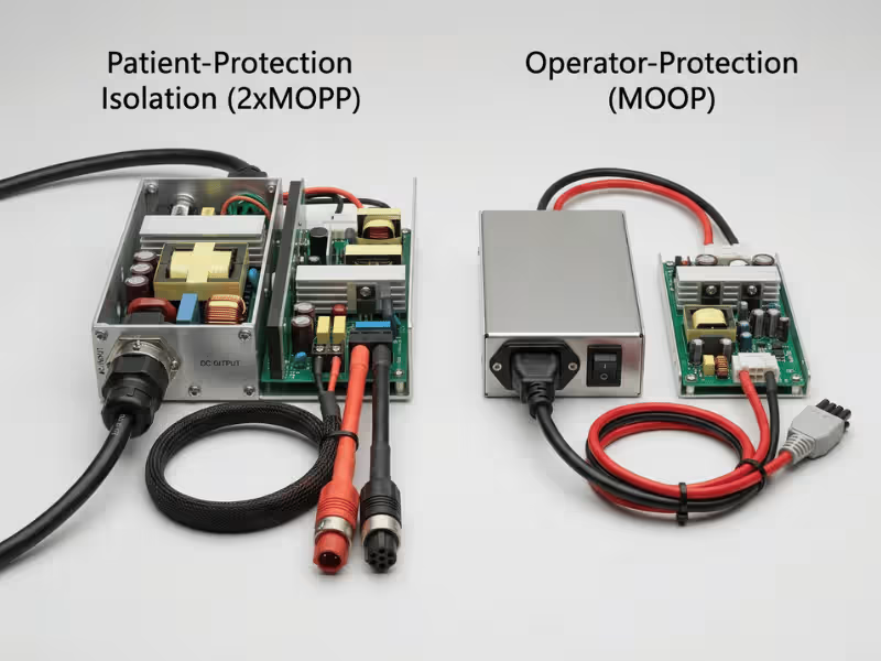
Patient Contact vs. Operator Access: The Distinction That Drives Everything
The MOPP-versus-MOOP decision largely reduces to one factor: who touches what, and under what fault conditions. To specify correctly, start by separating two kinds of parts.
An applied part is any part of the device intended to be in physical contact with the patient — an ECG lead, a blood-pressure cuff, a temperature probe, a dialysis line. An accessible part is one the operator touches during normal use, such as an enclosure, display, or control panel. In many medical device architectures, the isolation barrier behind an applied part is evaluated to MOPP, while a barrier associated only with an operator-accessible part is often evaluated to MOOP — provided no patient-connected path depends on that barrier.
Why the gap in strictness? A patient often cannot protect themselves. They may be sedated and unable to feel a fault, grounded through a metal bed frame, or internally connected so that even microamps of leakage matter. An operator, by contrast, typically has normal skin impedance, stands on an insulating floor, and can release a device the instant something feels wrong. The same fault current that startles an operator can, in the wrong patient path, be far more dangerous.
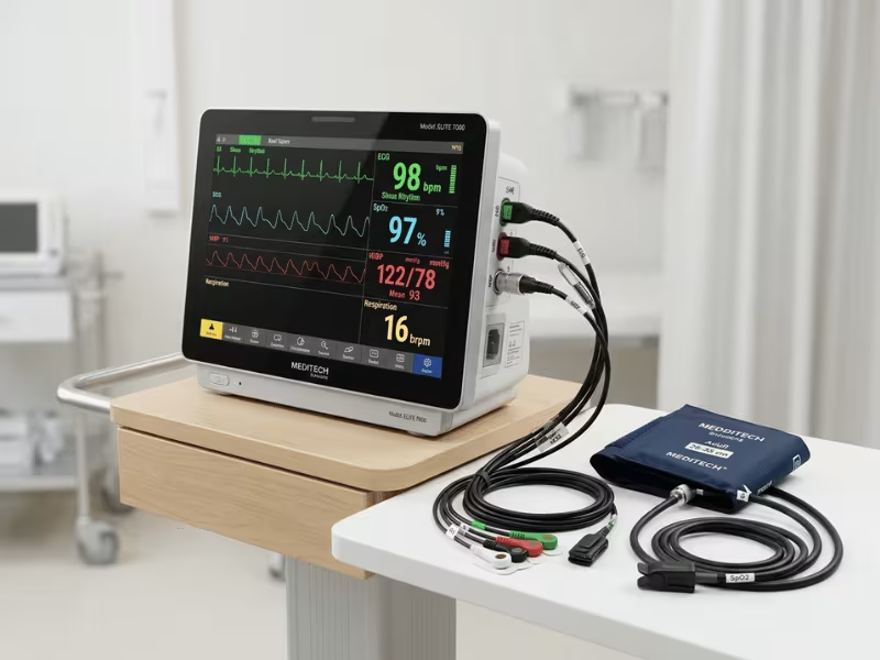
Consider a patient monitor. The ECG lead touching the patient sits behind a barrier evaluated to MOPP, because a fault there can flow into a vulnerable body. The mains-facing enclosure that only the nurse handles typically sits behind a MOOP barrier. One device, two classes — assigned by function and isolation path, not by a blanket rule.
Specification action: map every isolation barrier in your power tree, identify which barriers sit on patient-connected paths, and assign the protection class per barrier rather than per whole device.
Insulation and Leakage Current: What the Classes Actually Require
MOPP and MOOP stay abstract until you translate them into the parameters an engineer verifies on a datasheet. Two families of requirements do the heavy lifting: the isolation barrier itself, and the leakage current it allows through.
Creepage, Clearance, and Dielectric Strength
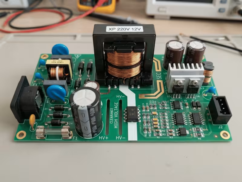
Three parameters define the physical isolation barrier. Creepage is the shortest distance along a surface between two conductive parts. Clearance is the shortest distance through air. Dielectric strength — verified by a hi-pot test — is the voltage the barrier can withstand without breaking down.
At the same working voltage, MOPP generally requires larger creepage and clearance than MOOP, and a higher dielectric withstand voltage. Representative figures discussed in design practice often place a MOPP barrier well above the equivalent MOOP barrier at the same voltage, but exact values depend on working voltage, insulation path, pollution degree, and the applicable edition — so confirm them against the relevant IEC 60601-1 tables rather than treating any single number as fixed. Where a single fault should never expose a patient, designs frequently apply 2× MOPP: two independent means of protection layered so that one failing still leaves the patient protected.
Specification action: confirm the datasheet states creepage, clearance, and dielectric withstand for the specific isolation path you rely on, and whether the rating represents 1× or 2× MOPP. Distances scale with working voltage, so any figure without its voltage context is incomplete.
Leakage Current Limits That Separate MOPP from MOOP
Leakage current is the small current that flows across isolation barriers under normal and single-fault conditions. IEC 60601-1 defines several categories, and they carry very different limits.
Earth leakage flows through the protective earth conductor and is typically bounded in the low-milliamp range. Touch (enclosure) leakage — what an operator could feel through an accessible part — is also generally bounded in the milliamp range. Patient leakage, the current that could flow through an applied part into the patient, is held to dramatically tighter limits, often in the microamp range depending on the applied-part type and whether conditions are normal (NC) or single-fault (SFC). Type CF applied parts, connected near or to the heart, sit at the strictest end. Confirm exact limits against your applied-part type and test condition in the applicable edition rather than relying on a single range.
These tight limits directly drive component choice. They constrain the isolation transformer’s interwinding capacitance and force careful selection — or elimination — of Y-capacitors bridging primary to secondary, since every picofarad adds leakage.
Specification action: match the supply’s stated patient leakage and earth leakage against your applied-part type, under both NC and SFC conditions. A supply that clears touch leakage can still fall short on patient leakage by an order of magnitude, so request the figures for each condition explicitly.
How IEC 60601-1 Frames the Decision
IEC 60601-1 is the standard that turns “protect the patient” into verifiable numbers. It generally sets MOP requirements based on the working voltage across a barrier and the person that barrier protects, which is why the same voltage can yield different creepage, clearance, and dielectric targets for MOPP versus MOOP.
The standard also classifies applied parts into three types, and this classification tends to raise or relax MOPP-related demands:
- Type B: applied parts with no direct conductive patient connection or lower patient-contact risk, carrying the least stringent patient-leakage limits.
- Type BF: floating (isolated) applied parts with a defined patient connection, generally requiring tighter isolation and lower leakage than Type B.
- Type CF: floating applied parts intended for direct cardiac contact, carrying the strictest leakage limits and the highest isolation expectations.
Layered on top is the concept of 2× MOPP for paths where a single failure should not endanger the patient — two independent barriers so protection survives one fault. Underpinning the whole exercise is risk management under ISO 14971: the standard generally expects you to justify protection choices against a documented risk analysis, rather than applying MOPP everywhere by reflex. In practice, your risk analysis helps determine whether a given barrier belongs to a patient-accessible path and what protection that path requires. Edition differences and national deviations also affect market access, so the edition you test against matters for where you can sell.
Specification action: confirm your applied-part type first, since it tends to set your leakage ceiling, then confirm the supply was tested to the IEC 60601-1 edition your target markets require.
When MOPP Is Required and When MOOP Is Sufficient
Costly mistakes run in both directions: under-specifying invites non-compliance, while over-specifying wastes money and board space. Assign the class per isolation barrier, not per whole device.
Consider MOPP when:
- The isolation barrier protects a patient-connected path — typically anything behind an applied part.
- Your applied part is Type BF or CF, where leakage limits are tight and cardiac risk may be present.
- A single fault on that path could expose the patient, which often triggers a 2× MOPP approach.
- Current could reach a grounded or internally connected patient who cannot withdraw.
MOOP may be sufficient when:
- The barrier stands only between hazardous voltage and the operator.
- No patient-contact path depends on that barrier for protection.
- The equipment is medical-grade in use but has no applied part, such as a cart-mounted display touched only by staff.
The common trap is assuming the entire power supply must be MOPP because the device is “medical.” In many designs, only the barriers on patient-connected paths call for MOPP. Applying blanket MOPP everywhere can inflate transformer size, creepage distances, and cost with no safety benefit on operator-only barriers. Conversely, treating a patient path as operator-only is a direct compliance and safety failure. Match the class to each barrier’s actual function, and document the reasoning behind each assignment.
MOPP vs. MOOP Across Real Medical Device Types
Mapping the decision to device categories makes it concrete. In each case, the driver is the applied-part type and whether a patient-contact path exists.
Patient monitors and ECG equipment connect directly to the patient through leads, so the applied-part path typically calls for MOPP — often with BF or CF classification depending on the measurement. Operator-facing barriers on the same unit can frequently be MOOP.
Infusion pumps and dialysis machines deliver fluids or blood along a conductive path close to or into the circulatory system, which often pushes them toward Type CF and stricter MOPP with 2× isolation on the patient path.
Imaging and lab or diagnostic equipment vary widely. Where a subsystem never contacts the patient — a control console or processing unit — MOOP may be sufficient. Where a probe or sensor touches the patient, that specific path generally needs MOPP.
Dental chairs and surgical tools are usually mixed designs: powered instruments with patient contact tend to need MOPP on those paths, while cabinetry and operator controls often need only MOOP.
Hospital-room and cart-based equipment that is medical-grade but has no applied part — think a monitor stand or a powered cart touched solely by staff — frequently qualifies for MOOP, because no patient-contact path depends on the relevant barrier.
Specification action: identify every patient-contact path in your device, classify its applied-part type, and assign MOPP there; assign MOOP only where you can demonstrate no patient path depends on that barrier. Because these requirements vary by device architecture and patient-contact path, it is often useful to review power needs in the context of specific medical device applications.
What to Verify in a Datasheet or Supplier Discussion
A “medical-grade” label alone tells you almost nothing about whether a supply meets your isolation needs. Before you commit, confirm the specifics against this checklist:
- Explicit MOPP/MOOP rating and isolation path. Confirm the supply states its class and for which path — input-to-output, input-to-ground, or output-to-ground. A single supply can carry different classes on different barriers.
- Dielectric withstand voltage, with 1× or 2× MOPP noted. Check the hi-pot figure and whether it represents one or two means of protection for the patient path.
- Leakage current figures against your applied-part type. Verify patient leakage and earth leakage under both NC and SFC conditions, and confirm they clear the limit for your Type B, BF, or CF part.
- IEC 60601-1 edition and deviations. Confirm the edition tested and any national deviations relevant to your target markets.
- Test report or certificate, not marketing copy. Ask for the actual documentation. A label is a claim; a test report is evidence.
- Classification matched to your barrier. Confirm the rated isolation path aligns with the barrier you depend on, not a generic assurance that the part is “for medical use.”
Treat any gap in this list as an open question for the supplier. If a datasheet omits the isolation path or reports leakage without stating the fault condition, you don’t yet have enough to trust it for a patient-connected design.

Where Quankang Supports Medical Power Specification
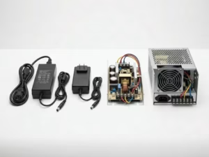
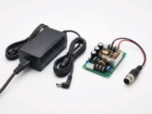
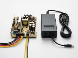
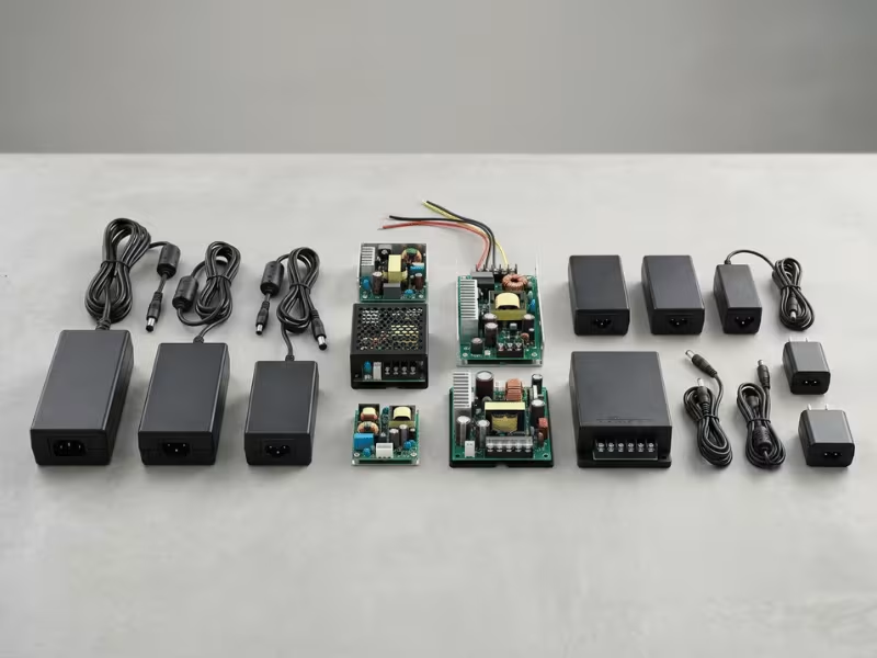
Quankang designs and manufactures medical power supplies and AC-DC adapters on an OEM/ODM basis, with isolation defined per path so MOPP and MOOP are assigned where each actually belongs. Whether you need an external medical-grade adapter or an embedded supply, our engineering team helps translate your device’s applied-part classification into concrete isolation and leakage targets rather than over-building every barrier by default.
That support covers a few areas buyers commonly struggle to pin down. We help map input-to-output, input-to-ground, and output-to-ground isolation paths to the right protection class, set patient- and earth-leakage targets aligned to Type B, BF, or CF applied parts, and align designs to the relevant IEC 60601-1 edition for your target markets. For audit-ready evidence, we can provide dielectric withstand data, leakage figures under both normal and single-fault conditions, and test documentation tied to the specific isolation path — not a generic “medical-grade” claim. The goal is a power solution that carries the right protection where it belongs, without paying for isolation you don’t need.
FAQ: MOPP, MOOP, and Medical Power Specification
Is 2× MOPP always required for medical power supplies?
No. 2× MOPP is generally applied on patient-connected paths where a single fault should not create a hazard, which is common in BF and CF designs. On operator-only barriers, applying it typically adds cost and size with no safety benefit. Whether it’s needed depends on the isolation path, intended use, and your documented risk analysis.
Can a medical device use a MOOP-rated power supply?
In some cases, yes. If no patient-connected path depends on the supply’s barriers — for example, a cart-mounted display or console touched only by staff — MOOP may be sufficient. Where the supply sits on a patient-connected path, MOPP is generally the appropriate class. Confirm which class applies to which specific barrier.
Is “medical-grade” the same as MOPP?
No. “Medical-grade” is a marketing term with no fixed isolation meaning. A supply can be medical-grade and provide only MOOP. Verify the explicit MOPP/MOOP rating, the isolation path, and the supporting test report before relying on it for a patient-connected design.
What does 2× MOPP mean on a power supply datasheet?
It indicates two independent means of patient protection layered together, so that a single fault in one still leaves the patient protected. Confirm which isolation path the rating applies to — for example, input-to-output or output-to-ground — since a datasheet may state different classes for different barriers.
How does applied-part type B, BF, or CF affect the requirements?
The type tends to set your leakage ceiling and isolation expectations. Type B is generally least stringent, Type BF adds floating isolation with tighter leakage limits, and Type CF — intended for direct cardiac contact — carries the strictest patient-leakage limits and the highest MOPP-related demands. Classify your applied part before finalizing leakage targets.
What patient leakage current limit applies to my device?
It depends on your applied-part type and test condition. Patient leakage limits are generally held to the microamp range, with Type CF at the strictest end and single-fault conditions typically allowing more than normal conditions. Confirm the exact figure in the applicable IEC 60601-1 edition against your classification rather than relying on a general range.
Key Takeaways and Next Step
- The class follows who the barrier protects and which isolation path it guards — not the device label.
- MOPP generally demands larger creepage and clearance, higher dielectric withstand, and much tighter leakage limits than MOOP at the same working voltage.
- Specify per barrier, not per whole device: MOPP on patient-connected paths, MOOP where only the operator is exposed.
- Classify your applied part (B, BF, or CF) first, since it tends to set your leakage ceiling and your 2× MOPP triggers.
- Verify documented ratings, isolation paths, and test reports under NC and SFC conditions — never a “medical-grade” label alone.
Specifying medical power is a decision about vulnerability and fault paths, made concrete through numbers you can verify. To match the right MOPP and MOOP isolation to your applied-part type, working voltage, and target-market standards, explore Quankang’s power solutions or contact us for OEM/ODM specification support.