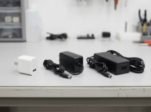
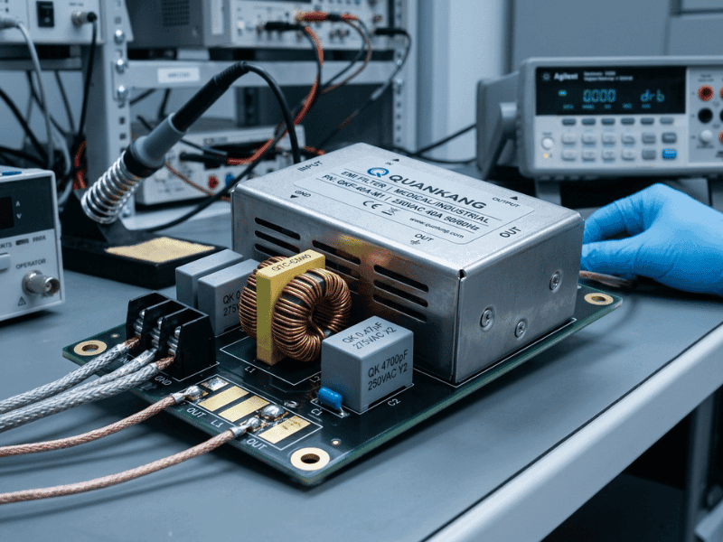
An EMI filter for a power supply is a passive circuit network placed at the AC power entry point to suppress high-frequency electromagnetic noise generated by switching circuits. It uses a combination of common-mode chokes, X capacitors, and Y capacitors to block both common-mode and differential-mode interference, helping power supplies meet conducted emission limits required for EMC certification.
Every switching power supply generates high-frequency electrical noise. That noise doesn’t stay inside the unit—it travels back into the AC mains and couples into nearby equipment. Without filtering, this interference can corrupt sensor signals, trigger false alarms in medical monitors, destabilize industrial control systems, and cause a product to fail conducted emissions testing before it ever reaches a customer.
An EMI filter is the component that stops this from happening. Placed at the AC power entry point, it suppresses the high-frequency noise produced by switching circuits, preventing it from propagating into the mains and ensuring the power supply meets applicable conducted emission limits in the target market.
This guide covers exactly how EMI filters work, what each component does, how to select the right filter for your application, and which design mistakes most commonly cause EMC test failures. Engineers and product managers working in industrial, medical, or power electronics will find specific guidance on selecting and correctly applying EMI filters—not just on understanding them in theory.
What Is an EMI Filter for a Power Supply?
An EMI filter for a power supply is a passive low-pass filter network connected between the AC mains input and the power supply’s internal switching circuit. Its function is to attenuate high-frequency conducted emissions—both those leaving the power supply toward the mains and, to a lesser extent, noise entering from the mains toward sensitive circuitry.
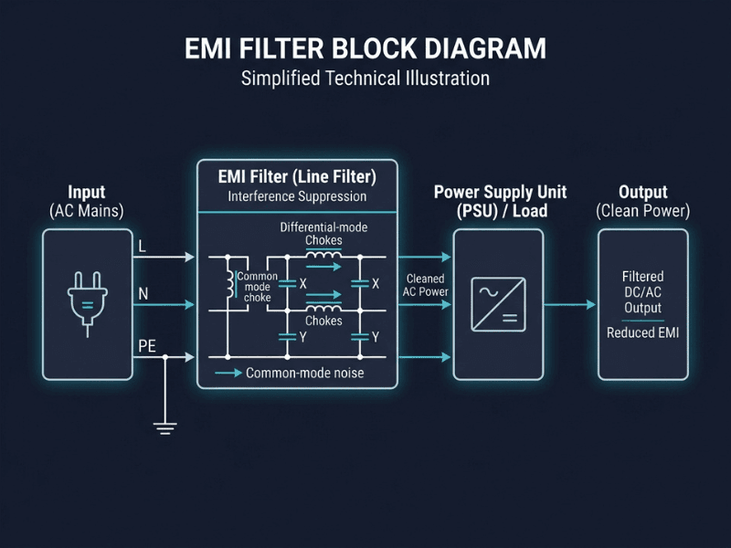
The filter operates on a straightforward physical principle: reactive components (inductors and capacitors) present high impedance to high-frequency signals while allowing low-frequency mains voltage (50 Hz or 60 Hz) to pass through with minimal attenuation. The result is a clean power interface between the mains network and the switching stage.
EMI filters are distinct from other protection components such as transient voltage suppressors or varistors. While those components absorb transient overvoltages, an EMI filter’s primary role is frequency-selective attenuation of conducted noise. It does not regulate voltage, correct power factor, or reduce total harmonic distortion (THD)—those functions are handled by other circuit elements.
Why Do Switching Power Supplies Need EMI Filters?
Linear power supplies draw a relatively smooth sinusoidal current from the mains. Switching power supplies operate on an entirely different principle: they switch transistors on and off at frequencies typically ranging from 50 kHz to several hundred kilohertz, converting AC to DC with high efficiency.
That switching action creates sharp current transitions. Fast edges in the switch node generate broadband harmonic energy that extends well into the MHz range. This energy couples onto the AC mains through both conductive paths and parasitic capacitances within the transformer and PCB.
The consequence is a conducted emission spectrum that, without filtering, exceeds the limits defined by regulatory frameworks such as CISPR 22/32 for IT equipment, CISPR 11 for industrial equipment, or the relevant medical EMC standard for class B limits. Failing conducted emissions testing delays product certification and market entry. Adding or optimizing an EMI filter at the design stage is far less costly than redesigning a product after an EMC test failure.
What Causes EMI in a Power Supply?
The primary EMI sources in a switching power supply are:
- Switch node transitions: The rapid switching of MOSFETs or IGBTs creates high dV/dt and dI/dt edges that generate broadband harmonic energy.
- Diode recovery: Rectifier diodes, particularly in the output stage, produce current spikes when they turn off.
- Transformer parasitic capacitance: High-frequency current flows through the interwinding capacitance of the isolation transformer, creating a conduction path that bypasses the intended circuit boundary.
- PCB layout parasitics: Long traces, poor ground-plane continuity, and inadequate separation between high- and low-frequency sections all contribute to EMI coupling.
The resulting noise appears on the mains in two distinct forms—common-mode and differential-mode—each requiring a different filtering strategy.
Common-Mode vs. Differential-Mode Noise: What’s the Difference?
Understanding the difference between these two noise types is essential for selecting and applying an EMI filter correctly.
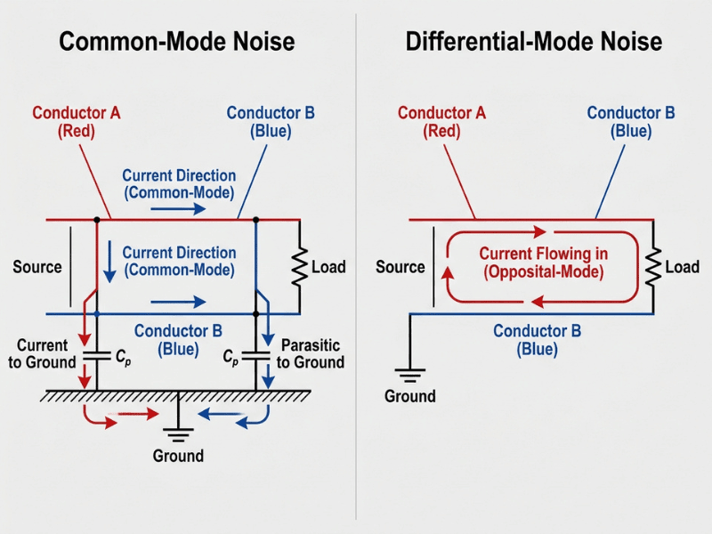
Differential-mode (DM) noise appears between the Line (L) and Neutral (N) conductors. It flows in opposite directions on each conductor—out on Line, back on Neutral—and is generated primarily by switching currents in the power conversion stage.
Common-mode (CM) noise appears identically on both Line and Neutral conductors simultaneously, with the return current flowing through the ground conductor, chassis, or parasitic capacitance paths to earth. Common-mode noise is typically generated by voltage switching on the primary side of the transformer, which couples through interwinding capacitance to the secondary and chassis.
In practice, both modes coexist in a switching power supply. An EMI filter must attenuate both, which is why it contains components specifically optimized for each mode.
What Are the Main Components of an EMI Filter?
Common-Mode Choke
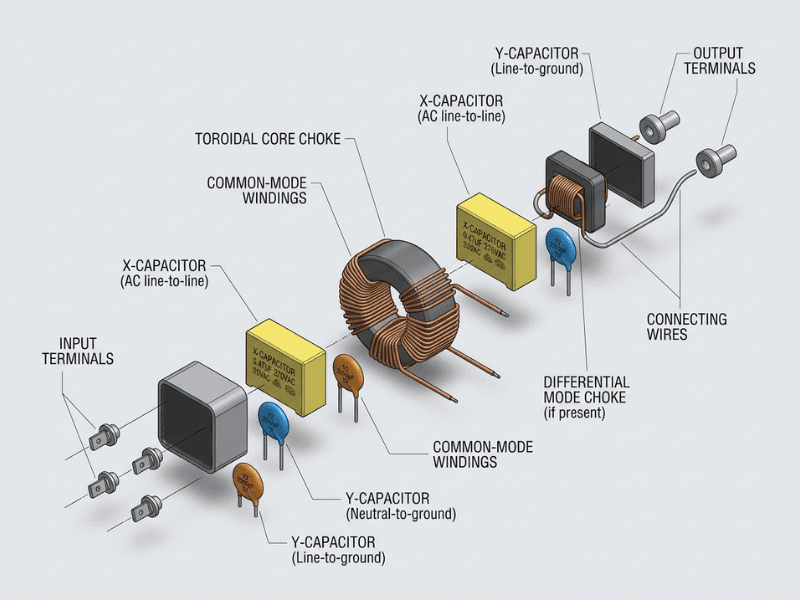
A common-mode choke is a transformer-like component wound on a single toroidal core. The Line and Neutral conductors pass through it in opposite directions. For differential-mode current, the magnetic fields generated by each conductor cancel inside the core—the component appears as a low-impedance path. For common-mode current (flowing in the same direction on both conductors), the fields reinforce each other, presenting high impedance and attenuating the noise.
Common-mode chokes are the highest-value inductive component in most EMI filter designs and provide the majority of common-mode attenuation across the filter’s rated frequency range.
X Capacitors
X capacitors are connected across the Line and Neutral conductors (line-to-line). They form an LC filter with the leakage inductance of the common-mode choke, thereby attenuating differential-mode noise. X capacitors are rated for continuous operation across the mains voltage and must safely fail open-circuit under fault conditions. They are classified as X1 (up to 4 kV peak), X2 (up to 2.5 kV peak), and X3—with X2 being the most commonly used class in standard power supplies.
Y Capacitors
Y capacitors connect from each conductor (Line and Neutral) to the protective earth or chassis. They provide a low-impedance return path for common-mode current, diverting it to ground before it can propagate further. Y capacitors must be rated for reinforced insulation between the mains and earth, and are classified as Y1 (suitable for double-insulation systems, rated at 500V AC) and Y2 (basic insulation, 300V AC).
The value of Y capacitors is critical in medical equipment applications because higher capacitance improves common-mode attenuation but increases leakage current—the current that flows from the mains through the Y capacitors to earth. Leakage current limits are strictly regulated in medical device standards, which typically restrict Y capacitor values to much lower levels than those used in industrial or IT equipment filters.
Additional Components
Many EMI filters also include a differential-mode choke (a separate inductor wound for DM noise), a metal oxide varistor (MOV) for transient overvoltage clamping, and inrush current limiting components. The MOV provides some protection against transient events, though it is not a substitute for a dedicated surge protection device in applications requiring robust overvoltage protection.
How Does an EMI Filter Work?
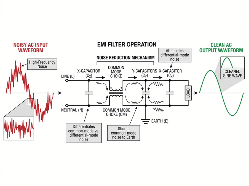
The filter operates as a two-stage attenuation network. High-frequency noise generated by the switching stage encounters the reactive impedance of the inductors and capacitors and is either reflected back toward the source or diverted to a low-impedance path before it reaches the mains.
The mechanism for each noise type:
- Common-mode noise is attenuated by the common-mode choke, which presents high impedance, and by Y capacitors, which provide a low-impedance return path to earth for high-frequency common-mode current.
- Differential-mode noise is attenuated by X capacitors shunting the noise current between Line and Neutral, and by the leakage inductance of the common-mode choke combined with any dedicated DM inductors.
The filter’s performance is characterized by its insertion loss—measured in dB at each frequency—which indicates how much it reduces the noise level at that frequency. Insertion loss is typically measured in a 50 Ω/50 Ω test system per CISPR standards. This is important to note: actual attenuation in a real power supply installation depends on the impedance of the mains network and the power supply’s input stage, which differ from laboratory test conditions. Published insertion loss data should be used as a comparative guide, not as an absolute predictor of system-level attenuation.
How to Choose an EMI Filter for a Power Supply?
Selecting the correct EMI filter requires matching multiple parameters to the application. Using an undersized or incorrectly specified filter is one of the most common reasons products fail conducted emissions testing.
Rated Voltage
The filter must be rated for the maximum mains voltage in the target market, including transient excursions. A filter rated for 250V AC is generally adequate for single-phase 230V systems. Confirm the voltage category matches the intended installation environment.
Rated Current
Choose a filter rated at or above the power supply’s maximum continuous input current. Derating applies at elevated temperatures—if the filter operates in an enclosure where ambient temperature exceeds its rated value, derate accordingly. An undersized filter will exhibit greater insertion-loss degradation and may overheat.
Single-Phase vs. Three-Phase
Single-phase filters are used for standard AC equipment with Line and Neutral connections. Three-phase filters are required for three-phase industrial equipment and motor drives. Verify the power supply’s input phase configuration before selecting.
Leakage Current Limits
This is the most critical parameter for medical equipment. Leakage current flows from the mains through Y capacitors to earth. Medical device standards impose strict limits on touch current and earth leakage current—often requiring total leakage current below 300 µA or less for equipment not in patient contact, and significantly lower limits for patient-connected applied parts.
Standard IT equipment and industrial filters typically use larger Y capacitors (which improve attenuation) but produce leakage currents of 1 mA or more—unacceptable in medical applications. Medical-grade EMI filters use lower-value Y capacitors to meet leakage limits, which requires compensating with higher-quality common-mode chokes and additional filtering stages to maintain adequate attenuation.
Choose a standard industrial EMI filter for industrial, IT, and communications equipment. Choose a medical-grade EMI filter for any device that falls under medical electrical equipment standards, where patient safety and leakage current compliance are non-negotiable.
Required Attenuation Range
Compare the conducted emissions profile of your power supply (measured without a filter or with an inadequate filter) against the applicable standard’s limit line. The gap between your measured noise level and the limit line at each frequency tells you how much insertion loss you need. Select a filter that provides that attenuation margin across the critical frequency range, typically 150 kHz to 30 MHz for conducted emissions.
Operating Environment
Consider temperature range, humidity, altitude, and vibration. Industrial filters must often withstand wider temperature extremes and harsher mechanical conditions than commercial-grade components. Confirm the filter’s environmental ratings match the application.
Safety Approvals
Verify that the filter carries the safety certifications required for the target market. Applicable approvals typically include UL recognition, CE marking under relevant directives, and CQC certification for the Chinese market. In medical applications, the filter and associated Y capacitors must comply with applicable reinforced insulation requirements.
Mounting Style
EMI filters are available in several form factors: panel-mount IEC inlet filters (which integrate the mains connector and filter into a single unit), chassis-mount filters with screw terminals, PCB-mount filters, and toroidal filter assemblies. The IEC inlet filter is often preferred for system-level designs because it places the filter at the exact point of mains entry, minimizing the length of unfiltered cable inside the enclosure.
Common EMI Filter Design Mistakes That Cause EMC Test Failure
Even a correctly specified filter can fail to perform if it is not implemented properly. These are the most frequent design errors:
1. Placing the filter too far from the power entry point
Any unfiltered cable between the mains inlet and the filter picks up noise and radiates it as an antenna. The filter must be located as close to the mains entry point as physically possible—ideally at the IEC inlet itself.
2. Poor grounding of the filter chassis connection
A Y capacitor diverts common-mode current to earth, but only if the earth path has low impedance. Long, thin earth wires or poor chassis bonding introduce inductance that reduces the effectiveness of the Y capacitors at higher frequencies. Use wide, short ground connections and direct chassis bonding.
3. Long unshielded traces between the filter output and the power supply input
High-frequency noise from the switching stage can couple back onto the filtered traces through stray capacitance. Keep the trace from filter output to power supply input short, and maintain physical separation from the unfiltered input traces.
4. Using the wrong X or Y capacitor class
X1 and X2 capacitors have different peak voltage ratings. Y1 and Y2 capacitors have different insulation levels. Using a Y2 capacitor in a double-insulated system, for example, may not satisfy the relevant safety standard. Always verify the capacitor class against the application’s insulation coordination requirements.
5. Ignoring leakage current limits during filter selection
Particularly in medical applications, selecting a filter primarily based on insertion loss without checking the resulting leakage current is a common and costly error. Measure or calculate total earth leakage current with all Y capacitors in circuit before finalizing the design.
6. Relying on insertion loss specifications without considering real system impedance
Published insertion loss data assumes a standardized 50Ω test environment. In a real system, the mains impedance and power supply input impedance differ significantly and are frequency-dependent. A filter selected purely on catalog insertion loss may underperform in the actual circuit. Pre-compliance testing in the real system is the only reliable validation method.
EMI Filter Applications in Industrial, Medical, and Power Electronics

Industrial Equipment
Variable-frequency drives, CNC controllers, industrial power supplies, and motor drives generate significant conducted emissions due to high switching frequencies and high power levels. Three-phase EMI filters with high rated current and robust construction for elevated ambient temperatures are standard in this sector. Attenuation requirements are typically governed by CISPR 11 Class A or Class B limits depending on the installation environment.
Medical Equipment
Medical power supplies—used in patient monitors, infusion pumps, ventilators, diagnostic imaging equipment, and surgical tools—face the strictest EMI filter requirements of any application category. Leakage current constraints drive component selection. The filter must provide adequate attenuation to meet conducted emission compliance requirements while keeping the total earth leakage current within the limits specified by applicable medical electrical equipment standards for the device’s patient-contact classification.
Quankang’s medical-grade AC-DC power supplies are designed with integrated EMI filtering validated to ≤100 µA leakage current with 2× MOPP isolation, meeting the requirements for patient-contact applied part equipment. Pre-compliance EMC data is available with every sample shipment.
IT and Communications Equipment
Servers, routers, switches, and telecom power systems require compliance with conducted emission limits applicable to information technology equipment. Standard IEC-inlet EMI filters with moderate Y-capacitor values are commonly used. The focus is on broadband attenuation across the 150 kHz to 30 MHz conducted band, with leakage current limits that are less restrictive than those for medical applications but still specified by applicable safety standards.
Power Conversion Systems
High-power converters, UPS systems, and renewable energy inverters pose complex EMI challenges because they produce both AC-side conducted emissions at the mains interface and additional noise from DC bus switching stages. EMI filtering strategy in these applications often involves multiple filter stages and careful attention to filter placement relative to both the mains entry and the converter output.
EMI Filter FAQ
What is the difference between a standard EMI filter and a medical EMI filter?
The key difference is leakage current. Standard and industrial EMI filters use larger Y capacitors to achieve high common-mode attenuation, which can result in leakage currents exceeding 1 mA. Medical EMI filters use smaller Y capacitors and higher-performance common-mode chokes to meet leakage current limits required by medical electrical equipment standards—typically below 500 µA for general medical equipment and lower still for equipment in direct patient contact.
Can one EMI filter cover multiple power supply ratings in the same product family?
Sometimes. If the power supplies in the family share the same input current range and operating environment, a single filter rated at the highest current level can often be used across the family. However, verify that insertion loss is adequate for the highest-power variant, and confirm that leakage current at full Y capacitor loading remains within limits for all variants.
What are the most common causes of conducted emissions failure even when an EMI filter is installed?
The most frequent causes are: filter placed too far from the mains entry point (allowing unfiltered cable to act as an antenna), inadequate grounding of the filter’s earth connection, long unshielded PCB traces between the filter output and the switching stage, and insufficient insertion loss for the actual noise level generated by the power supply. Real-system impedance mismatch between the filter’s rated test conditions and the actual installation also frequently reduces effective attenuation.
Should the EMI filter be placed at the PCB level or at the IEC inlet?
For most system designs, an IEC inlet-integrated EMI filter is preferable because it eliminates any unfiltered mains cable inside the enclosure. PCB-mount filters are appropriate when the system design places the power supply PCB directly at the mains entry point with no intervening cable, or when PCB size and cost constraints dictate the choice. In either case, the filter should be as close to the mains entry as possible.
What is an acceptable leakage current level for medical equipment?
Acceptable leakage current depends on the device classification and patient contact type. Equipment without applied parts (no patient contact) typically must meet higher leakage limits than B-type applied part equipment. BF-type and CF-type applied part equipment—used in direct patient contact or cardiac applications respectively—face the strictest limits. Consult the applicable medical electrical equipment standard and the specific device classification to determine the correct limit for a given application.
Does an EMI filter protect against power line surges?
An EMI filter is not a surge protection device. The MOVs sometimes included in filter assemblies can clamp moderate transient overvoltages, but they are not designed to absorb the energy levels associated with surge events defined by standards such as IEC 61000-4-5. For applications requiring surge immunity, a dedicated transient voltage suppression device should be used in conjunction with the EMI filter.
How can I determine whether my EMI filter is adequate before conducting a full EMC test?
Pre-compliance testing using a spectrum analyzer and a line impedance stabilization network (LISN) allows you to measure the conducted emission spectrum of your power supply with the filter in circuit and compare it to the applicable limit line. This identifies deficiencies before submitting the product for formal testing. Quankang’s in-house EMC laboratory offers pre-compliance scanning as part of the product development process, with a reported 98.3% first-pass EMC compliance rate across more than 10,000 OEM projects.
Specify Your EMI Filter with Confidence
Getting EMI filtering right is a system-level engineering decision, not a last-minute add-on. The filter topology, component ratings, leakage current budget, mounting position, and grounding scheme all interact—and errors in any one area can invalidate the work done in the others.
Quankang designs and manufactures AC-DC power supplies with integrated EMI filtering for medical, industrial, and IT applications. With 36 years of power supply development experience, 212 active patents, and an on-site EMC laboratory, Quankang provides pre-compliance EMC data with every sample, full certification documentation before purchase order, and application engineering support for products ranging from 5W portable medical devices to 1000W industrial power conversion systems.
If your power supply design requires EMI filtering guidance, pre-compliance validation, or a certified power supply solution for a medical or industrial application, contact Quankang’s engineering team for a technical review.