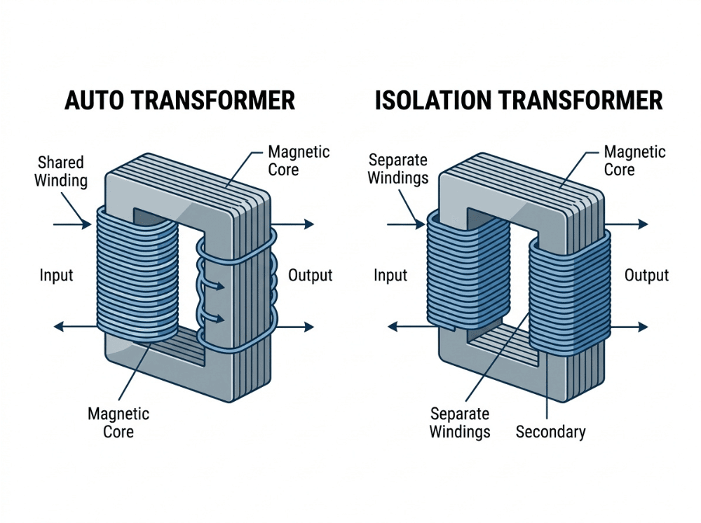
An auto transformer uses a single shared winding with no galvanic isolation between input and output. An isolation transformer uses separate primary and secondary windings, transferring power magnetically with no direct electrical connection between the two sides. Choosing between them comes down to one core question: does your application need efficient voltage conversion, or does it need electrical protection for people and equipment?
The choice between these two transformer types goes beyond voltage ratios or power ratings. It has direct implications for system safety, regulatory compliance, electromagnetic noise performance, and fault behavior—all of which carry real consequences in medical, laboratory, and industrial environments.
Both transformer types rely on the same underlying principle—electromagnetic induction—but their internal winding architectures differ in ways that have real consequences in deployed systems. Treating the two as interchangeable can lead to safety gaps, compliance failures, or performance problems that are significantly harder to address once a design is committed.
This guide covers how each transformer type works, where each is best suited, and what to consider when selecting among them based on your application’s actual requirements.
How Transformer Design Affects Performance and Safety
At its core, a transformer moves electrical energy between two circuits through a shared magnetic core. AC current in the primary winding creates a time-varying magnetic field that induces a voltage in the secondary winding. The turns ratio between primary and secondary sets the output voltage.
The mechanism is the same in both types. What differs is structure: how the windings relate to each other, and whether a direct conductive path exists between input and output.
That structural choice—shared winding versus separate windings—determines isolation capability, fault behavior, safety classification, and suitability for regulated applications.
What Is an Auto Transformer?
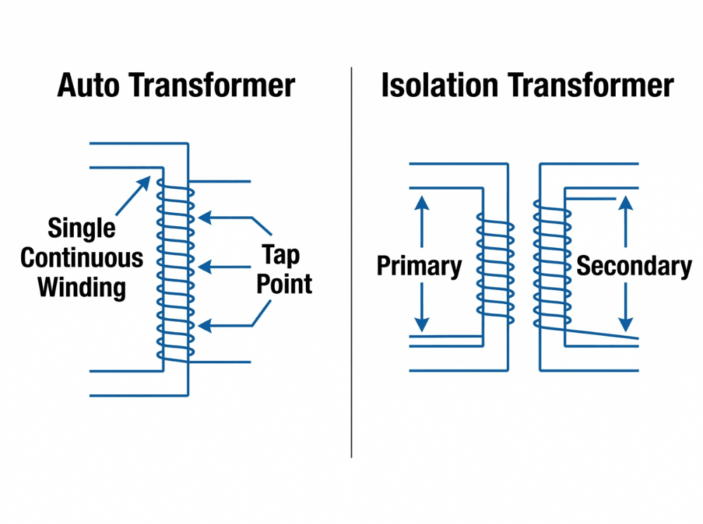
An auto transformer uses a single continuous winding that serves as both the primary and secondary. The output voltage is taken from a tap point on the same winding rather than from a separate coil. The input and output share a common section of conductor.
Because less copper and core material are required, auto transformers are smaller, lighter, and less expensive than isolation transformers of equivalent power rating. They also tend to be more efficient, particularly when the voltage ratio between input and output is close to 1:1. Losses are lower because only a portion of the total power is transferred electromagnetically—the rest is transferred by direct conduction.
Common applications include:
- Line voltage adjustment (e.g., adapting 208V equipment to a 240V supply)
- 110V/220V conversion for equipment used across international markets
- Motor soft-starting to reduce inrush current
- Industrial power distribution where voltage steps are modest
- Bench and laboratory voltage adaptation for non-safety-critical loads
The critical limitation: An auto transformer does not provide galvanic isolation. The load circuit has a direct electrical connection to the mains supply through the shared winding. This makes the auto transformer unsuitable for any application where electrical separation between source and load is required for safety or compliance reasons.
What Is an Isolation Transformer?
An isolation transformer uses two separate, magnetically coupled windings—a primary and a secondary—wound on a shared core but with no direct metallic connection between them. Power is transferred entirely through the magnetic field in the core.
This separation is called galvanic isolation. No conductive path exists between the primary (mains) side and the secondary (load) side. As a result, the transformer can significantly reduce the direct transfer of hazardous mains potential to the load and help limit common-mode noise coupling—though the degree of protection in any given system also depends on grounding configuration, insulation design, and overall system architecture.
Isolation transformers are frequently built with a 1:1 turns ratio—meaning the output voltage equals the input voltage. The purpose in these cases is not voltage conversion but electrical separation.
Key benefits:
- Removes the direct conductive path between the mains and the load
- Can help reduce ground loop interference in sensitive signal chains, depending on the grounding configuration
- Attenuates common-mode electromagnetic noise at the winding boundary
- Supports floating secondary configurations, subject to overall system grounding design
- Helps meet compliance requirements where safety standards mandate a defined isolation barrier
Common applications include:
- Medical equipment (patient-contact devices, diagnostic instruments, monitoring systems)
- Laboratory and test equipment
- Industrial control panels and PLC systems
- Audio and video equipment sensitive to ground loops
- Service benches for live equipment repair
- Sensitive electronics requiring clean, noise-attenuated power
Auto Transformer vs Isolation Transformer: Key Differences
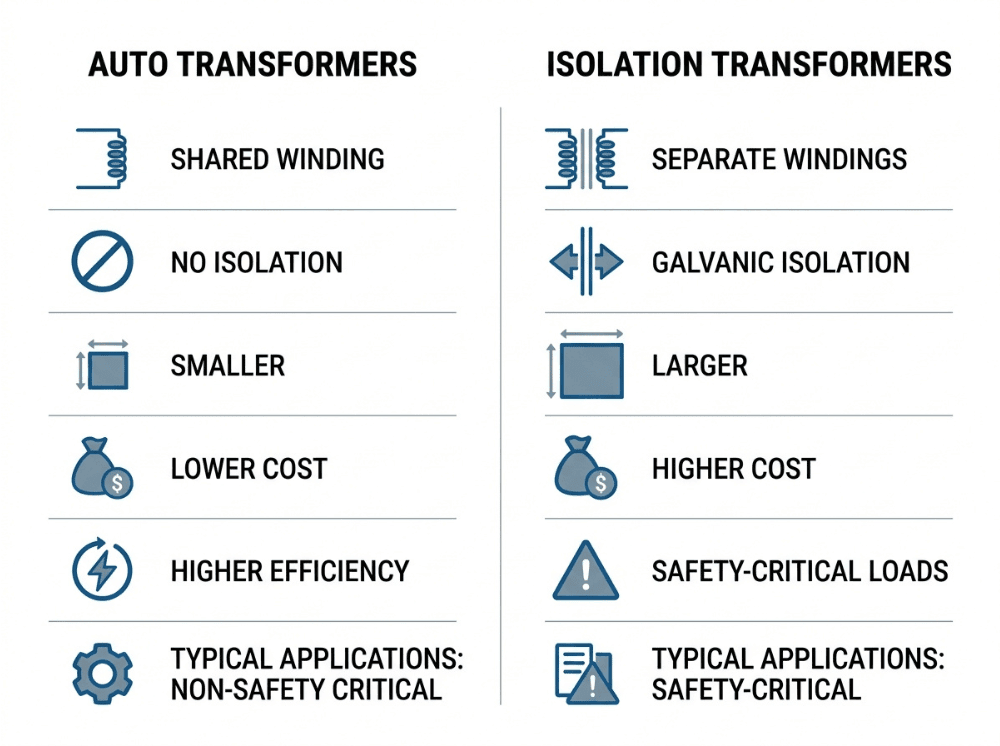
The table below summarizes the primary technical and application differences:
Parameter | Auto Transformer | Isolation Transformer |
|---|---|---|
Winding design | Single shared winding | Separate primary and secondary windings |
Galvanic isolation | None | Yes |
Direct electrical connection | Input and output share a conductor | No direct conductive path |
Size and weight | Compact and lightweight | Larger and heavier |
Material cost | Lower (less copper and core) | Higher |
Efficiency | Higher (partial electromagnetic transfer) | Slightly lower |
Electrical safety protection | Limited—load connected to mains | High—load separated from mains |
Noise/EMI handling | Minimal attenuation | Attenuates common-mode noise |
Voltage conversion | Yes (stepped up or down from tap) | Yes (or 1:1 for isolation only) |
Typical use case | Voltage matching, motor starting, and industrial adaptation | Medical, lab, instrumentation, noise-sensitive loads |
The most consequential difference is galvanic isolation—not voltage conversion. Both transformer types can step the voltage up or down. Only the isolation transformer breaks the conductive link between the input and the output.
How Winding Architecture Shapes Real-World Performance
The shared winding in an auto transformer reduces the amount of copper and core steel required. This translates directly into lower manufacturing cost, reduced physical size, and lower resistive losses. For applications where the input and output voltages are relatively close together, an auto transformer can achieve efficiencies above 98%.
The tradeoff is electrical continuity. Because input and output share a common conductor, certain fault conditions—such as insulation breakdown or winding failure—can allow hazardous mains potential to appear at the load. Unlike a two-winding design, the shared conductor does not provide an inherent interruption point between the source and the load circuit.
An isolation transformer’s separate windings substantially reduce the risk of hazardous mains potential reaching the load side. Because the primary and secondary are physically and electrically distinct, the secondary circuit is separated from the mains by the inter-winding gap and the insulation system surrounding each coil. Under most fault conditions, this separation means that primary-side insulation degradation does not create a direct conductive path to the load—though it is worth noting that insulation systems have defined limits, and no isolation architecture eliminates risk entirely. This is what makes isolation transformers well-suited to floating-output configurations and to applications where standards require a verifiable isolation barrier between the mains and the load.
Under fault conditions, the transformer’s architecture determines whether hazardous energy can reach personnel or downstream equipment. That consideration belongs in the design specification, not the post-installation review.
Safety and Grounding: How the Two Transformers Differ
Because an auto transformer provides no galvanic isolation, the load circuit remains conductively linked to the mains supply at all times. Under certain fault conditions—such as winding insulation breakdown or a short within the shared conductor—hazardous mains potential can appear at the load terminals. Personnel in contact with the load circuit may be exposed to dangerous earth-referenced voltages, depending on the system’s grounding configuration and the nature of the fault.
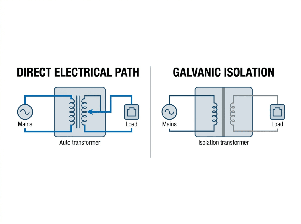
An isolation transformer can support a floating secondary—one where neither output terminal is connected to protective earth—depending on how the system is grounded. This configuration limits the shock current that flows through a person who contacts one output terminal while standing on earth, because there is no low-impedance return path to the mains ground. This is distinct from eliminating shock risk entirely; grounding strategy, enclosure design, and leakage current limits all contribute to overall safety.
Industries where isolation is either mandatory or strongly recommended include:
- Medical equipment: Standards such as IEC 60601-1 require defined levels of protective isolation between mains and patient-accessible parts. Leakage current limits (typically ≤ 100 µA for patient-contact devices) cannot be reliably met without isolation. See Quankang’s IEC 60601-1 medical power supply range and the related 2×MOPP isolation guide for detailed compliance context.
- Laboratory and test equipment: Instruments used for live circuit testing, electrical characterization, and calibration typically require an isolation boundary to protect both the operator and the instrument.
- Marine and offshore: Isolated power distribution systems are common practice in marine environments where fault currents through seawater create specific electrocution risk profiles.
- Industrial maintenance benches: Technicians servicing energized equipment benefit from a secondary circuit that is not directly referenced to mains ground.
Where standards explicitly require a defined isolation barrier—IEC 60601-1 being the most widely referenced example—an auto transformer cannot satisfy that requirement through electrical performance alone. The absence of galvanic isolation is a structural characteristic, not a performance variable, and no operational refinement changes that fundamental fact.
Efficiency, Size, and Cost: Auto Transformer vs Isolation Transformer
For applications where voltage conversion is the primary requirement, and the voltage ratio is less than approximately 2:1, auto transformers offer a genuine engineering advantage. Less core steel and copper wire means lower material cost, reduced weight, and a smaller physical footprint. Efficiency in the 97–99% range is achievable for closely spaced voltage ratios.
As the voltage ratio increases, the efficiency advantage of the auto transformer diminishes. A larger portion of power must be transferred electromagnetically rather than by conduction, and the winding design approaches that of a conventional two-winding transformer.
Isolation transformers require more material for equivalent power output. Separate primary and secondary windings each require their own conductor volume, and the insulation system between windings adds size and cost. At a 1:1 ratio, where the transformer performs no voltage conversion at all, the entire value proposition is the isolation barrier itself.
When making a procurement decision, it helps to think of the two transformer types as optimized for different goals. Auto transformers are built around efficiency and cost. Isolation transformers are designed with protection, noise attenuation, and regulatory compliance in mind. Neither is a universal winner—each fits a different set of system requirements, and the right choice depends on which requirements actually apply to your application.
Typical Applications for Each Transformer Type
Auto transformer applications:
- Adjusting supply voltage to match equipment ratings (e.g., 200V equipment on a 208V supply)
- Soft-starting large induction motors to limit inrush current
- Industrial power distribution where modest voltage steps are required across non-safety-critical loads
- International voltage conversion on bench equipment where isolation is not required
Isolation transformer applications:
- Medical systems where patient safety and leakage current compliance drive the power supply specification
- Laboratory and calibration instruments where common-mode noise from the mains supply corrupts measurements
- Industrial control panels where signal integrity and ground loop elimination are required
- Audio and video equipment where ground-referenced noise creates audible or visible artifacts
- Service benches for live equipment testing
- Any application where applicable standards require a defined isolation barrier
Choosing the Right Transformer for Medical and Sensitive Equipment
For medical systems and precision instrumentation, the transformer type is rarely an efficiency question. It is a safety and compliance question.
IEC 60601-1 establishes means of protection (MOPP) requirements between mains and patient-accessible parts. Meeting these requirements depends on a verifiable isolation barrier between input and output — something an auto transformer cannot provide by design. The standard specifies minimum creepage distances, clearances, and dielectric withstand levels that are defined relative to an isolation boundary. Where no such boundary exists, those requirements cannot be evaluated or satisfied in any meaningful way.
Beyond compliance, the engineering concerns in medical and sensitive equipment include:
- Leakage current: Isolation can help limit the capacitively coupled current flowing from the mains to the output under normal operating conditions. Standards such as IEC 60601-1 require patient-contact devices to remain within defined leakage limits—typically ≤ 100 µA—which generally necessitates a verifiable isolation barrier.
- Common-mode noise: Mains-borne electromagnetic interference can couple into the load circuit through the shared conductor of an auto transformer. Isolation transformers can attenuate this noise at the winding boundary, though the degree of attenuation depends on the transformer’s construction and the system’s overall grounding design.
- Fault behavior: Under certain fault conditions in an auto transformer—such as insulation breakdown or a short within the shared winding—hazardous mains potential may appear at the load terminals. An isolation transformer’s separate winding structure reduces this risk by introducing a physical and electrical separation between the primary and secondary circuits, though no isolation architecture eliminates fault risk entirely.
- Grounding flexibility: Isolated secondary circuits can be configured with defined grounding schemes that support tighter control over fault current paths, which is one reason isolation is often preferred in safety-critical and sensitive measurement applications.
For engineers specifying power systems for medical devices, laboratory instruments, or equipment where safety depends on the power supply architecture, isolation is generally the appropriate starting point—not because auto transformers are inherently poor choices, but because the isolation barrier is a structural requirement in most regulated applications, and it is far easier to design around than to retrofit. For applications outside those safety-critical contexts, the decision depends on the system’s specific requirements, not on a blanket preference for one type. For further context on EMI and EMC considerations relevant to power supply design, see Quankang’s EMI vs. EMC guide.
How to Choose the Right Transformer for Your Application
Use the following criteria to guide selection:
Quick Selection Guide
Choose an auto transformer if:
- You need voltage conversion only, with no isolation requirement
- Input and output voltages are close together (ratio below ~2:1)
- Cost and physical size are primary constraints
- The load is not safety-sensitive and no regulatory isolation requirement applies
- The application is industrial voltage adaptation or motor starting
Choose an isolation transformer if:
- User or patient safety depends on the power supply architecture
- Galvanic isolation is required by applicable standards (e.g., IEC 60601-1)
- The load is sensitive electronics subject to common-mode noise or ground loop interference
- The application is medical, laboratory, test, or regulated industrial
- Compliance documentation must demonstrate a defined isolation barrier
Transformer selection should be driven by system risk and regulatory requirements, not cost and efficiency alone. In regulated or safety-sensitive applications, the savings from choosing a cheaper auto transformer can be quickly offset by compliance failures, redesign costs, or—more seriously—safety incidents that could have been avoided with the right design from the start.
Frequently Asked Questions
Is an auto transformer the same as an isolation transformer?
No. An auto transformer uses a single shared winding, meaning the input and output circuits are electrically connected. An isolation transformer uses separate primary and secondary windings with no conductive path between them. The two types differ in safety behavior, noise performance, and regulatory suitability.
Does an auto transformer provide galvanic isolation?
No. Galvanic isolation requires a complete physical separation between input and output circuits. Because an auto transformer’s windings share a common conductor, a direct electrical connection exists between input and output. Galvanic isolation is only achievable with a transformer that uses separate, magnetically coupled windings.
Why is an isolation transformer considered safer than an auto transformer?
An isolation transformer has no direct conductive path between the mains supply and the load circuit. This limits fault current propagation, reduces shock risk when a person contacts one output terminal, and enables leakage current to be controlled within defined limits. An auto transformer’s shared winding means hazardous mains voltage can appear at the load under fault conditions.
Can an auto transformer be used for medical equipment?
Generally, no. Standards such as IEC 60601-1 require defined means of protection (MOPP) between mains and patient-accessible parts. These requirements assume an actual isolation barrier, which an auto transformer does not provide. Using an auto-transformer in a patient-contact application would not meet the isolation requirements of IEC 60601-1.
What Type of Transformer Should I Use for Sensitive Laboratory Instruments?
For sensitive laboratory instruments, an isolation transformer is generally the more appropriate choice. Isolation can help reduce common-mode noise from the mains supply, minimize ground loop interference, and improve measurement stability—though the degree of improvement depends on the instrument’s design, the grounding scheme, and the overall system environment. An auto transformer, lacking galvanic isolation, does not offer these benefits.
Do auto transformers protect against power surges?
Auto transformers do not provide meaningful protection against voltage surges or transients originating on the mains supply. Because the input and output are conductively connected, surge energy passes directly to the load. Isolation transformers offer some attenuation of high-frequency transients due to the capacitive characteristics of the inter-winding insulation, but dedicated surge protection devices are the correct solution for transient suppression.
When is a 1:1 isolation transformer necessary?
A 1:1 isolation transformer is used when the objective is electrical separation, not voltage conversion. The output voltage equals the input voltage, but the output circuit is galvanically isolated from the mains. This configuration is common in medical environments, service bench setups, laboratory power distribution, and applications where ground loop interference must be eliminated without changing the supply voltage.
What happens if the common winding in an auto transformer fails?
If the shared winding in an auto transformer fails—through insulation breakdown, conductor damage, or an internal short—the absence of galvanic isolation means there is no inherent electrical boundary to contain the fault. Depending on the nature and location of the failure, hazardous mains potential may appear at the load terminals. This is a meaningfully different fault profile from that of an isolation transformer, where the physical and electrical separation between the primary and secondary windings reduces the likelihood of mains potential propagating directly to the load side—though no isolation architecture eliminates fault risk entirely.
Selecting the Right Transformer Starts With the Right Question
Auto transformers and isolation transformers are not competing solutions to the same problem. They solve different problems, and confusing them carries real consequences.
Auto transformers deliver efficient, compact voltage conversion where electrical isolation is not required. They are the practical choice for industrial voltage adaptation, motor starting, and equipment matching in non-safety-critical environments. Isolation transformers deliver something an auto transformer structurally cannot: a defined electrical boundary between mains and load. That boundary is what medical device standards, laboratory safety protocols, and noise-sensitive applications actually require.
The best transformer for a given application is the one that matches the safety classification, noise tolerance, and compliance requirements of the full system—not the one with the lowest unit cost or the smallest footprint.
For engineers working on medical devices or regulated industrial systems, power supply isolation is a design constraint that needs to be addressed early—not resolved at the compliance stage. Quankang’s medical-grade AC-DC power supplies are built to IEC 60601-1 requirements, with leakage current ≤ 100 µA and 2× MOPP isolation as standard design parameters. If you have specific isolation requirements or are evaluating options for a current project, Quankang’s engineering team is available to discuss the technical details.