Medical devices don’t get the same margin for error as industrial equipment. When a device connects to the human body — through an electrode, a catheter, or a probe — the electrical safety requirements change entirely. Even a few microamps of unwanted current flowing through a patient can trigger cardiac fibrillation under the right conditions.
That’s the core challenge of patient leakage current in medical devices.
This guide covers what leakage current is, why it’s impossible to fully eliminate, how medical power supply design drives the numbers, what IEC 60601 leakage current requirements actually demand, and the specific techniques that reduce leakage at the design level. If you’re an engineer, compliance professional, or product team working on mains-connected medical equipment, this is the technical grounding you need.
What Leakage Current Is — and Why It Can’t Be Zero
Understanding leakage current starts with a simple physical reality: no real component is ideal. Every capacitor, transformer winding, and insulated cable has stray capacitance, and AC voltage drives current through those capacitances whether you want it to or not.
The Physical Roots of Leakage
Leakage current flows through unintended paths in a circuit. These paths exist in two forms:
Capacitive leakage occurs wherever AC voltage appears across a capacitance — including stray capacitance between PCB traces, transformer windings, cable conductors and shields, and filter components. The relationship is direct: higher frequency and larger capacitance mean more leakage current.
Resistive leakage occurs through imperfect insulation. No material has infinite resistance. Moisture, contamination, and material aging all degrade insulation over time, opening resistive paths that allow DC and low-frequency leakage.
The design goal in medical device electrical safety is not elimination — it’s control. You manage leakage current down to levels that pose no measurable risk to patients under any realistic operating condition.
The Three Leakage Current Types
IEC 60601-1 distinguishes three types of leakage current, each with different risk profiles:
- Earth leakage current flows from mains-connected parts through the protective earth conductor. It’s the easiest to measure and the least directly threatening to patients under normal conditions.
- Enclosure leakage current flows from any touchable surface of the device to earth. This becomes a patient risk when a person touches the enclosure while connected to the device through another path.
- Patient leakage current flows through the applied parts — the portions of the device in direct contact with the patient. It is the most tightly regulated because it bypasses the body’s natural skin impedance, allowing it to reach vulnerable internal tissues.
Why Patient Leakage Current Is Uniquely Dangerous
Of the three leakage types, patient leakage current in medical devices is subject to the strictest limits. The reason is physiological.
Healthy skin provides significant impedance against external electrical current. When a device connects through an electrode on the chest, an intravascular catheter, or a cardiac lead, that protection disappears. The current enters the body at a sensitive internal site, and the threshold for harm drops dramatically.
Intracardiac current as low as 10 µA can induce ventricular fibrillation in vulnerable patients. That’s a value smaller than what most people can feel, and far below anything that would trip a standard overcurrent protection device.
Applied Part Classification: B, BF, and CF
IEC 60601-1 uses applied part classification to link device function to leakage current limits. Getting this right at the start of a project is non-negotiable.
Type B parts make body contact but are not electrically connected to the patient circuit — lowest risk, least restrictive limits.
Type BF parts are floating (isolated from earth) and are used for general body contact — intermediate limits.
Type CF parts are also floating but meet significantly stricter limits because they’re intended for direct cardiac application — ECG electrodes near the heart, intracardiac catheters, pacemaker leads.
The CF classification doesn’t just change a number on a compliance checklist. It determines the isolation architecture, the insulation barrier strategy, and the leakage current budget for every component in the signal chain, from the power supply to the patient. Misclassifying an applied part at the concept stage leads to redesigns that are far more expensive than getting it right the first time.
Where Patient Leakage Current Comes From
The dominant source is capacitive coupling across the isolation barrier inside the power supply — specifically, from the primary (mains) side to the secondary (patient-facing) side through the transformer’s interwinding capacitance. Y-capacitors, added across that barrier for EMI suppression, make a major additional contribution.
Secondary sources include PCB trace coupling across the isolation boundary, cable capacitance (especially in long, unshielded patient cables), and chassis coupling in devices where the enclosure bridges the mains and patient-facing sections.
In devices with multiple applied parts, inter-patient leakage is an additional concern. Voltage differences between signal circuits can drive current between two applied parts, and that path exists even when the main isolation barrier is functioning correctly.
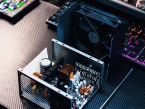
How Medical Power Supply Design Drives Leakage Current
The power supply is the largest single contributor to patient leakage current in most mains-connected medical devices. Its architecture sets the leakage floor before any signal circuitry is added.
Why Switching Frequency Matters
A switched-mode power supply (SMPS) generates high-frequency common-mode voltage across the isolation barrier at every switching transition. This voltage drives current through the transformer’s interwinding capacitance and any other capacitances across the barrier.
The math is unforgiving: double the switching frequency, and you roughly double the leakage current for the same physical capacitance. This is a critical consideration for modern GaN and SiC-based power supplies operating at several hundred kHz — a transformer that was compliant at 100 kHz may produce twice the leakage at 400 kHz.
Two transformer parameters control how much leakage originates from the magnetics:
- Interwinding capacitance (Cps): The capacitance between primary and secondary windings. Lower values reduce leakage directly. Achieved through physical separation, Faraday shielding, or choices in winding geometry.
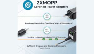
- Creepage and clearance distances: IEC 60601-1 specifies minimum values based on the working voltage and pollution degree. These aren’t just compliance boxes — they determine whether the isolation remains effective in the real world amid humidity and contamination.
The Y-Capacitor Problem in Medical Power Supply Design
Y-capacitors are placed across isolation barriers to suppress common-mode EMI. They’re effective at that task — but they create a direct capacitive path from the mains side to the secondary side, which contributes directly to patient leakage current.
A quick calculation illustrates the scale of the problem. At 50 Hz mains with a 240 V supply, a 4.7 nF Y-capacitor across the isolation barrier produces:
I = 2π × f × C × V = 2π × 50 × 4.7×10⁻⁹ × 240 ≈ 350 µA
That single capacitor can consume most — or all — of the leakage budget for a Type BF applied part. For Type CF, it may already exceed the limit.
This is the clearest differentiator between a general-purpose industrial SMPS and a genuine medical-grade power supply. Medical designs typically limit Y-capacitors to 470 pF or less, or eliminate them entirely and address EMI through other means.
IEC 60601 Leakage Current Requirements: What You Need to Know
IEC 60601-1 is the international standard governing the safety of medical electrical equipment. For leakage current, it defines measurement conditions, patient measurement networks, applied part limits, and mandatory test configurations.
Normal Conditions and Single Fault Conditions
The standard requires testing under both normal conditions (NC) and single fault conditions (SFC). Single fault tests simulate realistic failure scenarios: loss of earth connection, an interrupted supply conductor, a component failure. Each scenario has defined leakage limits that are stricter than normal condition values.
The most demanding scenario — a CF applied part measured under single fault conditions — produces limits that constrain design decisions across the entire patient-facing signal chain.
Three practical requirements that are frequently underestimated during pre-compliance testing:
- Leakage current must be measured using the patient measurement network specified in IEC 60601-1 — the physiological equivalent circuit that models human body impedance. A simple ammeter substitution gives results that don’t correlate with the standard’s limits.
- Testing must be performed at 110% of nominal mains voltage. A design that passes at 230 V may fail at 253 V.
- For devices with unidentified mains plugs, both polarity configurations must be tested. Worst-case leakage often occurs under reversed-polarity conditions.
Collateral and Particular Standards
IEC 60601-1 is the base document, but it’s not the only one. The 60601-2-xx particular standards add device-specific requirements for cardiac monitors, infusion pumps, electrosurgical units, and other product types. Collateral standards address EMC (60601-1-2), usability (60601-1-6), and home healthcare environments (60601-1-11).
Home-use devices warrant specific attention. IEC 60601-1-11 applies when devices operate outside clinical settings — lower mains quality, no environmental controls, users without clinical training. Devices intended for home healthcare need tighter leakage margins and more robust isolation than their hospital equivalents.
Reducing Leakage Current: Where to Act and How
Leakage current reduction is a system-level problem. There’s no single fix. You reduce it by making correct decisions at every stage, from transformer specification to cable routing.
Transformer and Winding Design
Reducing interwinding capacitance is the highest-leverage intervention available. Three approaches work:
Physical separation between primary and secondary windings reduces capacitive coupling. The trade-off is transformer size and efficiency — a real constraint in compact devices.
Faraday electrostatic shields — a grounded conductive layer between windings — intercept displacement current before it crosses the barrier. When connected to the correct reference point (typically secondary ground in a medical application), a Faraday shield can reduce interwinding capacitance by an order of magnitude. Note: An incorrectly connected shield can increase leakage rather than reduce it.
Non-interleaved winding geometry keeps the primary and secondary as physically separate as possible. Interleaved structures improve efficiency but increase interwinding capacitance — the opposite of what medical applications need.
Controlling Y-Capacitor Values
Once you understand the 350 µA example above, the strategy becomes clear:
- Replace high-value Y-capacitors with values at or below 470 pF, and compensate with alternative EMI mitigation.
- Add a common-mode choke on the primary input to reduce the common-mode voltage across the barrier — thereby reducing the effective leakage contribution of any remaining Y-capacitors.
- Use a well-connected, Faraday-shielded transformer to replace part of the Y-capacitor’s noise-suppression function.
- In isolated medical DC/DC converters, evaluate whether the secondary-side circuit needs a Y-capacitor at all. Many compliant designs omit it entirely on the patient-facing output.
PCB Layout and Isolation Boundaries
Good component choices can be undermined by poor PCB implementation. The isolation barrier must be maintained across the entire board, not just at the transformer.
Keep high-voltage primary traces and secondary traces as far apart as the board allows. Never run them in parallel for extended distances — parallel routing maximizes capacitive coupling between them.
Use a split ground plane with a clear physical gap at the isolation barrier. Don’t bridge it with a ground pour. The only intentional crossings should be the transformer, optocouplers or digital isolators, and any deliberately placed Y-capacitors.
Verify that creepage and clearance distances for all isolation components — including optocoupler packages, capacitive isolators, and digital isolators — meet IEC 60601-1 Annex G requirements for your working voltage. Not every component marketed as “medical-grade” has been tested to the specific creepage requirements for your application.
Cable Shielding and Enclosure Decisions
For applied part cables, connect the shield to the device’s secondary-side ground — not to mains earth. Keep cable length as short as the application allows. For Type CF applied parts, use individually shielded conductors within multi-conductor cables to minimize inter-conductor coupling.
Enclosure material choices directly affect leakage current paths. A conductive enclosure connected to mains earth provides strong EMI shielding but creates an enclosure leakage path to any touchable surface. A non-conductive plastic enclosure eliminates that path but requires internal shielding to meet EMC requirements.
For Class II (double-insulated) medical devices without a protective earth connection, the double-insulation system — reinforced insulation or two independent barriers — must provide adequate protection against both electric shock and leakage current under all test conditions.
System Integration: Every Interface Matters
In complex devices, leakage current accumulates across subsystem boundaries. Map every conductive path from mains potential to any patient-facing conductor. This includes:
- USB and Ethernet interfaces that simultaneously connect to a mains-powered host and a patient-facing circuit
- Display interfaces where the backlight driver operates at mains-referenced voltage
- Battery charging circuits where the charger’s isolation barrier sits in series with a patient-connected battery
USB deserves explicit analysis. The USB 5 V bus can remain live even when the device appears idle, and cable capacitance between USB ground and the host’s mains earth adds directly to patient leakage current. Isolated USB interface ICs eliminate this contribution entirely.
Leakage Current Testing: Building a Budget Before the Lab
Correctly testing leakage current is not about passing a certification test. It’s about understanding what your design actually does — and catching problems before they become expensive.
Build a Bottom-Up Leakage Budget
Before the first prototypes, estimate leakage contributions from each major source:
- Transformer interwinding capacitance: Get measured Cps values from your magnetics supplier, or measure them directly on samples.
- Y-capacitors: Calculate using I = 2π × f × C × V.
- PCB barrier coupling: Estimate based on parallel trace lengths and their separation.
- Cable capacitance: Calculate from the cable datasheet parameters and actual cable length.
- Isolation component capacitance: Check datasheets for the specified isolation capacitance of each component across the barrier.
Sum the contributions. Compare to the applicable limit with a 20–30% margin to account for production variation. If the total exceeds the target, identify the largest contributors and address them before ordering hardware. Leakage problems found on paper are far cheaper to fix than those found at third-party certification testing.
Medical Device Electrical Safety: Where Requirements Are Heading
The leakage current landscape is shifting alongside the technology in the devices themselves.
GaN and SiC power supplies operating at higher frequencies increase capacitive leakage per unit of stray capacitance. Medical power supply designers adopting wide-bandgap semiconductors need to recalculate their leakage budgets for the new operating frequencies — existing designs don’t automatically transfer.
Wireless connectivity adds new leakage paths. RF circuitry connected to antennas is electrically referenced to the device, and that relationship can contribute to patient leakage current in devices where the RF module shares ground with the patient-facing circuit. Leakage contributions from Bluetooth, Wi-Fi, and cellular front-ends require explicit treatment in safety analyses.
Home healthcare and wearable devices present a specific challenge. Many battery-operated patient-contact devices connect to mains-powered charging accessories. The leakage current during charging events — when the isolation barrier between the charger and the patient-facing battery circuit matters most — is frequently underanalyzed during development.
IEC TC62 amendments continue to refine requirements, particularly in home-use environments, EMC, and usability. Development teams with multi-year product cycles need to monitor TC62 publications proactively, not just at the point of certification submission.
Actionable Guidance for Engineering and Compliance Teams
Organized by project phase, here’s what to actually do:
At concept and architecture:
- Classify all applied parts (B, BF, CF) before any circuit design begins — classification determines everything downstream.
- Map all conductive paths from mains potential to patient-facing conductors, including accessories and communication interfaces.
- Request leakage current data from power supply vendors during evaluation, not after qualification.
During component selection:
- Specify isolation transformers with measured Cps values, Faraday shields, and creepage/clearance dimensions verified against IEC 60601-1 Annex G.
- Set Y-capacitor values based on calculated leakage contribution — not based on EMI suppression defaults carried over from industrial designs.
- Verify every isolation component meets working voltage, creepage, and clearance requirements for its specific position in your circuit.
During PCB design:
- Make the isolation boundary review a formal part of the design review process.
- Document all isolation barrier crossings on the layout.
- Route applied-part signal traces away from primary-side high-voltage nodes.
Before and during testing:
- Use the IEC 60601-1 patient measurement network — not a simplified substitute.
- Test at 110% of nominal mains voltage, both polarity configurations, and all single-fault conditions.
- Record results with explicit margin documentation, not just pass/fail entries.
For accessories and integration:
- Analyze leakage for every accessory that can simultaneously connect to a patient-facing interface and a mains-connected interface.
- Include leakage current analysis in accessory compatibility documentation, especially for USB and data interfaces.
Conclusion
Patient leakage current in medical devices is a direct line between circuit-level decisions and patient outcomes. It’s not a compliance formality to resolve at the end of development — it’s a parameter that needs to be designed for from the first architectural decision.
Start with the correct applied part classification. Build a leakage current budget before prototyping. Choose isolation transformers and Y-capacitor values with leakage in mind, not just EMI performance. Maintain consistent isolation boundaries across PCB layout and system integration. Test thoroughly, under the conditions the standard actually specifies.
The devices that reliably protect patients over their service life are the ones for which these decisions were made deliberately — not discovered during certification.
Frequently Asked Questions
What are the leakage current limits for medical equipment?
Leakage current limits for medical electrical equipment are defined by safety standards such as IEC 60601-1 (also referenced as 60601-1). These limits specify allowable leakage current for different applied part types (type BF and type CF), enclosure leakage, earth leakage current, and patient auxiliary current under normal conditions and single-fault conditions. Regulatory bodies set different numerical limits depending on whether the leakage is to protective earth (protective earth current), to applied parts (direct contact with patients), or between floating patient connections (body floating or cardiac floating). Ensuring compliance with these leakage limits is essential to ensure the safety of these devices in medical applications.
How does leakage current in medical equipment affect patient safety?
Leakage current in medical equipment can be an unintended electrical current that reaches the patient via the applied part connected or through enclosure leakage. Excessive leakage current, especially in contact with the heart or cardiac floating cases, can pose a hazard. Safety standards for medical devices require limits on leakage and tests to control insulation, grounding, and impedance so that any electrical current remains within allowable leakage current ranges. Proper design and grounding, including protective earth and isolation transformers, reduce risk and help ensure the safety of patients and clinical staff.
What are the differences between type BF and type CF applied part leakage requirements?
Type BF (body floating) and type CF (cardiac floating) applied parts have different leakage limits and testing criteria in IEC 60601-1 because of the severity of consequences if the heart is affected. Type CF applied parts have the most stringent limits for leakage current, patient auxiliary current, and enclosure leakage current because they can contact the heart. Type BF applied parts allow higher leakage thresholds but still require control of insulation, grounding, and earth leakage. Designers must follow medical equipment standards, using isolation, capacitors, impedance control, and appropriate enclosure practices to meet these limits.
What are common sources of unintended leakage current in medical equipment?
Common sources of unintended leakage current include capacitive coupling (for example, between primary and secondary windings of a transformer), degraded insulation, conductive contamination on enclosures, faulty grounding or protective earth connections, and intentionally leaked currents through suppression capacitors or EMI filters. Environmental conditions, worn components, and poor design practices can affect leakage current. Identifying the source—whether enclosure leakage, earth leakage, or leakage through applied parts—helps determine corrective measures such as insulation replacement, improved grounding, or redesign.
How can manufacturers control leakage current during design and development?
During design and development, manufacturers control leakage current by applying safety standards for medical electrical equipment (IEC 60601-1), selecting appropriate insulation, using isolation transformers, minimizing capacitance between mains and patient circuits, and designing low-impedance protective earth connections. Techniques include selecting components with appropriate voltage ratings, avoiding conductive paths that could allow unintended current to reach applied parts, separating high-voltage and patient-accessible circuits, and performing pre-compliance leakage testing under normal conditions and during fault simulations. Documenting design choices and risk assessments helps demonstrate compliance with regulatory bodies.
What test methods are used to measure enclosure leakage and earth leakage current?
Enclosure leakage and earth leakage current are measured using standardized tests from IEC 60601-1, which specify test configurations, applied voltages, and measurement equipment. Tests often apply AC or DC voltages between the mains and protective earth or enclosure, and measure resulting currents with defined impedance loads to simulate contact with patients or earth. Measurement may include simulating the applied part connected to body models, measuring patient auxiliary current, and verifying limits under normal and single-fault conditions. Calibration and traceable instruments are required to ensure accurate results and compliance with leakage limits.
What should clinicians do if they suspect excessive leakage current from a device?
If clinicians suspect excessive leakage current or unintended current (for example, tingling, shocks, or equipment heating), they should stop using the device and disconnect the patient if safe to do so. Report the event to biomedical engineering or device maintenance for inspection. Trained technicians should check protective earth continuity, perform leakage tests, inspect insulation and enclosure integrity, and review grounding and transformer isolation. Documentation of symptoms and device conditions supports the investigation and ensures patient safety, while regulatory reporting may be required for suspected failures that do not meet safety standards for medical equipment.
How do environmental conditions and clinical setup affect leakage current in medical applications?
Environmental conditions such as humidity, conductive contamination (fluids), and the presence of other electrical equipment can raise enclosure leakage and earth leakage. Clinical setup factors such as grounding (protective earth quality), connections among multiple devices, electrode placement, and whether a patient is connected to multiple applied parts influence overall leakage paths and impedance. These variables can affect leakage current and interactions between devices; therefore, ensuring proper grounding, regular maintenance, adherence to standards, and proper patient isolation reduces the risk of unintended contact with electrical current and helps maintain compliance with leakage current limits.
What design and maintenance practices ensure compliance with leakage current requirements?
To ensure compliance with leakage current requirements, adopt safety-focused design practices—proper insulation selection, reduced coupling via capacitors, adequate separation of patient circuits, use of isolation transformers, and earth leakage protection. During manufacturing and lifecycle maintenance, perform routine leakage testing, verify protective earth continuity, inspect enclosures for conductive contamination, replace degraded insulation, and follow IEC 60601-1 test procedures. Training staff, documenting changes, and engaging with regulatory guidance from the International Electrotechnical Commission and other regulatory bodies help maintain safety and ensure the safety of these devices for medical applications.