A compact controller passes every bench test, then fails radiated emissions at the certification lab. A sensor module that looked fine on paper runs hot enough inside its sealed enclosure to cut capacitor life in half. In many of these cases, the circuit design is sound, and the real mistake is the power architecture. Choosing between a linear power supply and a switching power supply sets your thermal budget, EMI risk, enclosure size, and unit cost before you build the first prototype.
Engineers and buyers often confuse the two because both deliver regulated DC, and the datasheets look similar. The way each one gets there is completely different, and those differences show up in your product.
This guide breaks down the linear power supply vs. switching power supply decision. It covers how each works, where they differ, why each trade-off exists, which applications favor which design, and a checklist you can apply to your next project.
What Is a Linear Power Supply?
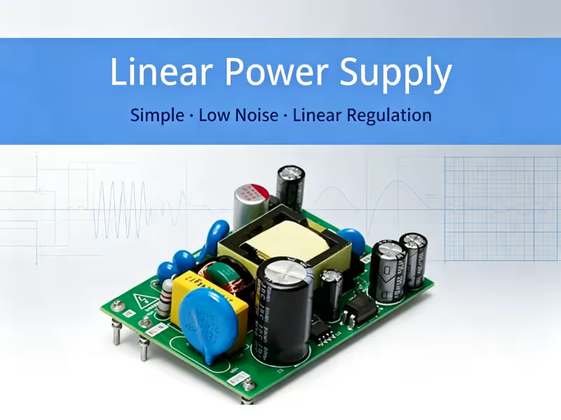
A linear power supply regulates output voltage by running current through a pass transistor that works like a variable resistor. It continuously drops the excess voltage, with no high-frequency switching involved.
The classic build follows a simple path: a 50/60 Hz step-down transformer, then a rectifier and smoothing capacitor, then a linear regulator that holds the output steady. The regulator constantly adjusts its resistance to absorb changes in input voltage and load. That steady control is why the output is so clean. It is also why the regulator wastes power as heat.
Linear supplies have long been used in audio equipment, laboratory and test instruments, and sensitive analog circuits, where a quiet output matters more than efficiency.
What Is a Switching Power Supply?
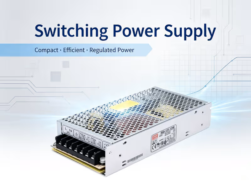
A switching power supply regulates output voltage by turning a transistor fully on and off at high frequency, typically tens of kHz to several MHz. It then filters the resulting pulses into smooth DC.
The core path consists of a switching transistor (usually a MOSFET), a high-frequency transformer or inductor, and an output rectifier and filter. A control loop adjusts the duty cycle, which is the ratio of on-time to off-time, to hold the output at its target. Switching frequency drives the whole design. Higher frequency allows smaller magnetics and capacitors, but it also raises switching losses and electromagnetic noise.
Switching supplies power most consumer electronics, industrial controls, and compact high-power systems where size and efficiency matter most.
Core Differences Between Linear and Switching Power Supplies
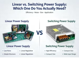
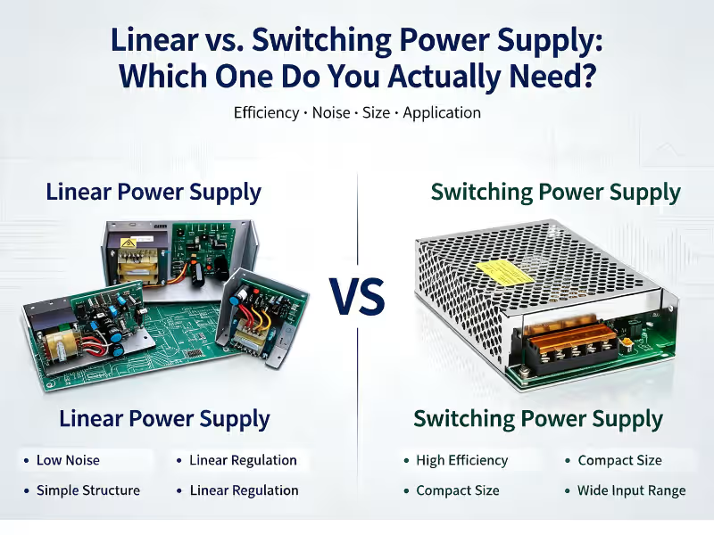
Here is a quick comparison of the linear power supply vs switching power supply across the factors that drive real design decisions.
Dimension | Linear Power Supply | Switching Power Supply |
|---|---|---|
Regulation method | Pass transistor drops excess voltage continuously | Transistor switches on/off at high frequency; duty cycle sets output |
Efficiency range | Roughly 40–60% (depends on input-output headroom) | Roughly 80–95%+ |
Output ripple/noise | Very low; no switching noise | Higher; includes switching ripple and HF noise that needs filtering |
Size & weight | Large and heavy (50/60 Hz transformer, heatsinks) | Compact and light (HF magnetics, smaller capacitors) |
Heat generation | High; wasted power scales with voltage drop × load current | Low overall, but concentrated in small components |
Typical cost at scale | Cheapest at low power; rises steeply with wattage | More components, but more cost-effective at mid-to-high power |
Each row in this table affects the others. Efficiency drives heat, heat drives size, and the switching mechanism that delivers efficiency is also what creates noise. The next section explains why.
Pros and Cons Across Key Dimensions
Linear Power Supply Efficiency vs. Switching Efficiency
The efficiency gap comes down to physics, not build quality. A linear regulator’s pass transistor carries the full load current while also dropping the full voltage difference between input and output. That loss equals (V_in − V_out) × I_load.
Take a common case: 12 V in, 5 V out, 2 A load. The load gets 10 W, and the regulator burns 14 W. That works out to about 42% efficiency, and nothing in the design can improve it.
A switching transistor avoids this by spending almost no time in the lossy middle ground. When it is fully on, the voltage across it is near zero. When it is fully off, current is near zero. Either way, the voltage-times-current product stays small. Losses come mainly from conduction resistance, switching transitions, and the magnetics. That is how a good switching power supply reaches 85–95%. In a design with a wide input voltage range, this gap gets even larger because a linear supply must be designed for the worst case: high line voltage at full load.
Heat Generation & Thermal Management
Lost efficiency becomes heat, and heat drives the mechanical design. A linear supply delivering 50 W at 50% efficiency has to dissipate another 50 W. That means large heatsinks, airflow, or derating the supply to run below its rating.
In sealed enclosures, this can rule out linear designs entirely. Thermal problems also spread to other parts: electrolytic capacitor life roughly halves for every 10 °C rise. A switching supply produces much less total heat, but it is concentrated in small parts such as the MOSFET, the output rectifier, and the transformer core. Hot spots replace bulk heat. Good copper pours, thermal vias, and careful component placement matter more than heatsink size. Both designs need a thermal plan, just a different kind.
Noise & Switching Power Supply EMI
This is where the linear power supply earns its place. Its pass element never switches, so it produces no high-frequency energy. The only ripple left is low-frequency (100/120 Hz) residue from rectification, and the regulator’s power supply rejection suppresses most of it. The result is an output measured in microvolts of noise, which suits low-level analog, precision ADC references, and RF front ends.
A switching supply works by creating fast voltage and current edges, high dV/dt and di/dt, and those edges spread energy across a wide spectrum. Noise shows up as conducted emissions on the input and output lines and as radiated emissions from switching loops and magnetics.
Designers manage this with several tools:
- Input EMI filters (common-mode chokes, X and Y capacitors)
- Snubbers to tame ringing
- Tight PCB layout that keeps high-current switching loops small
- Shielded magnetics
- Spread-spectrum frequency modulation
A useful technique many engineers overlook is the hybrid approach. Use a switching stage for efficient bulk conversion, then add a low-dropout linear regulator for the noise-sensitive rail. You get most of the efficiency and most of the quiet.
Size & Weight
Transformer size scales inversely with operating frequency. A linear supply’s transformer runs at 50/60 Hz, so it needs a large iron core and plenty of copper to carry power without saturating. A switching supply’s transformer runs hundreds or thousands of times faster, so a ferrite core a fraction of the size can carry the same power. Filter capacitors shrink for the same reason.
In practice, a switching supply can be several times smaller and lighter than a linear unit with the same output. In a handheld device, a DIN-rail module, or a 1U chassis, that difference usually decides the architecture.
Cost & Complexity
At low power, linear wins on simplicity. A transformer, a bridge rectifier, a few capacitors, and a regulator IC make a design with few parts, little layout risk, and no EMI tuning.
That advantage fades as power rises. Linear designs need more copper, more steel, and more heatsink for every added watt, and shipping heavy units adds cost too. Switching supplies carry more components and require more engineering work, including control-loop compensation, magnetics design, and EMC testing. Those costs are largely fixed, though, while material costs grow slowly with power. Beyond roughly 10–20 W, and especially at volume, switching usually becomes cheaper overall. Energy-efficiency regulations for external power supplies also push many designs toward switching.
Which Is Better for Different Applications?
None of these trade-offs matter on their own. They only matter in the context of what your application actually needs. A noise advantage means little in a phone charger, and an efficiency advantage means little in a bench preamp drawing 3 W.
A linear power supply is the better fit for:
- Audio amplifiers and preamps: Low-level signals pick up supply noise easily, and a linear rail removes a whole category of hum and whine problems.
- Precision lab and test instrumentation: Benchtop supplies, signal analyzers, and measurement front ends where low output noise is part of the product’s value.
- RF-sensitive circuits: Receivers, oscillators, and low-noise amplifiers where switching harmonics can land directly in the band of interest.
- Low-noise medical sensing: ECG, EEG, and similar front ends that measure microvolt-level signals and cannot tolerate added interference.
A switching power supply is the better fit for:
- Consumer electronics: Chargers, adapters, and smart devices where size, weight, and efficiency standards matter most.
- Telecom and networking equipment: High-density racks where every watt lost is a watt of cooling to pay for.
- Industrial automation: PLCs, motor drives, and DIN-rail systems that need wide input ranges and compact footprints.
- Compact high-power embedded systems: Edge computing, LED drivers, and battery-powered systems that need to step up or step down voltage, which linear regulators cannot do for step-up at all.
Application categories point you in a direction. The final decision comes from matching your actual specifications to the architecture.
How to Choose Based on Real Requirements
Let the specification decide, not habit or preference. Before you commit to an architecture, answer these five questions with numbers:
- How sensitive is your circuit to output noise and ripple? Set a figure in mV peak-to-peak or µV RMS, along with the frequency band that matters. If your circuit tolerates 50 mV of switching ripple, a switching supply works. If it needs microvolt-level noise in the audio band, start with linear or a switching-plus-LDO design.
- What are your size and weight limits? Define the enclosure volume, board area, and mass. A tight enclosure often rules out linear before any other factor.
- What is your efficiency target and thermal budget? Work out how many watts the enclosure can dissipate at maximum ambient temperature. Then calculate linear losses at high line and full load, not at typical conditions.
- What is your production volume and target unit cost? At low volume and low power, linear’s simplicity saves engineering cost. At high volume, switching’s lower material cost usually wins.
- Which EMI/EMC standards do you need to meet? Identify the target markets and standards early, such as CISPR 32, FCC Part 15, or IEC 60601 for medical equipment. A switching design can pass, but EMI filtering and layout have to be planned from the start, not added after a failed test.
With these answers in hand, choosing the architecture becomes straightforward. Choosing a manufacturer who can deliver it reliably is the next step.
Partner with Quankang for the Right Power Supply Fit
Neither design is better in every case. The right choice depends on your specific requirements for noise, efficiency, size, and cost.
That is the work Quankang’s engineering team does with customers every day. Instead of having you pick from a datasheet and hope the margins hold, we review your load profile, thermal limits, enclosure, and compliance targets. We then recommend the architecture that fits, whether that is a standard switching supply, a low-noise linear design, or a hybrid built for your system. When a catalog part does not quite fit, we can adapt or develop a custom power supply that does.
Send us your requirements. Contact the Quankang team at quankang-cn.com for a technical consultation or a custom quote. Bring your specs, and we will help you choose the right power supply the first time.
FAQ
Is a switching power supply always more efficient than a linear one?
No. When input and output voltages are close, such as 3.6 V to 3.3 V, a low-dropout linear regulator can exceed 90% efficiency. At very light loads, a switching supply’s fixed overhead can also drag its efficiency below a simple linear design.
Can a linear power supply be used for high-power applications?
Yes, but it gets expensive quickly. High-power linear supplies exist, mostly in lab equipment and high-end audio, and they need heavy transformers and large heatsinks. Above a few hundred watts, the size, weight, and heat usually make linear impractical.
Why do switching power supplies need EMI filtering and linear ones don’t?
Switching supplies create fast voltage and current edges that spread energy across a wide frequency range, both through wires and through the air. A linear regulator never switches, so it produces almost no high-frequency noise to filter.
Which type of power supply is better for audio equipment?
Linear power supplies are the safer choice for preamps, DACs, and low-level analog stages because they produce no switching noise. Many modern Class-D amplifiers use well-filtered switching supplies successfully, so a careful hybrid design is often the best balance of noise performance and efficiency.