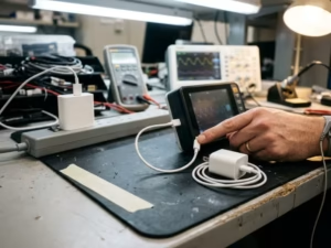
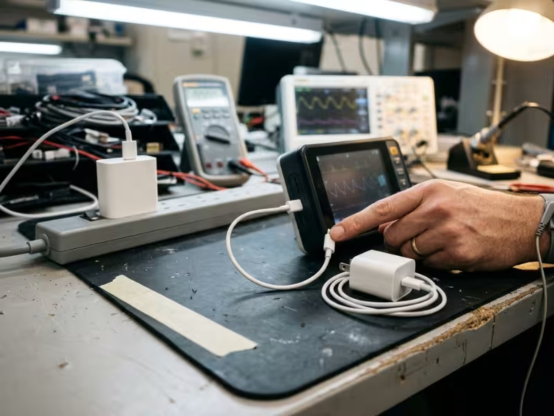
A portable patient monitor passes EMC testing with its approved USB PD charger. Then the team swaps in a second charger from the same approved list. The monitor resets halfway through the immunity test.
Home use raises the risk. A patient loses the original charger and plugs in a phone charger from the kitchen drawer.
I work with OEM design and regulatory teams who assume the USB-C connector solves the power problem. It doesn’t.
USB PD is negotiated, not fixed. The charger and the device agree on voltage and current every time they connect, and that changes everything for compliance.
This guide covers standards checks, technical verification before design freeze, supplier control, and home-use replacement risk.
What Makes USB PD Different in a Medical Device System
Most teams treat a USB-C charger like any other external power supply. That assumption holds until you look at what happens on the wire. Three behaviors set USB PD apart, and each one ends up in your test plan.
Negotiated Power Isn’t Fixed DC Input
A fixed adapter outputs one voltage the moment you plug it in. A 12V barrel-jack supply delivers 12V every time, from every unit.
A USB PD source starts at 5V. The device asks for more over the CC line. The charger then offers its power profiles, usually 5V, 9V, 15V, and 20V. The voltage steps up only after both sides agree.
That agreement can break. A hard reset drops VBUS to 0V and restarts at 5V. A loose cable, a firmware glitch, or an ESD hit can trigger one. Your device may lose its input for a few hundred milliseconds. A fixed adapter never does that on its own.
USB-C and USB PD also aren’t the same thing. A USB-C port without PD often supplies only 5V.
The Cable Becomes Part of the Power Path
With a barrel jack, the cable just carries current. With USB PD, the cable affects what the charger will deliver.
Any contract above 3A needs an e-marked cable. The e-marker chip tells the source that the cable can carry 5A. Without it, a 100W charger caps itself at 60W (20V × 3A). A 65W device works fine with the bundled cable and falls short with a generic one.
Resistance matters too. A long, thin cable can drop several hundred millivolts at 3A and eat into your input margin.
I ask teams to treat the cable as a controlled part, with its own part number and its own verification.
PPS Lets the Input Voltage Move
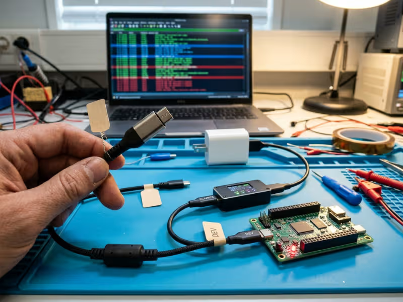
PPS (Programmable Power Supply) lets the device request voltage in 20 mV steps, often from about 3.3V to 21V. Phones use it for direct battery charging.
On a medical device, your input rail stops being a short list of known values. A PPS source can also enter current-limit mode and pull the voltage down under load. The device must also refresh its PPS request about every 10 seconds, or the source triggers a hard reset.
If your design doesn’t need PPS, block it in firmware early.
Feature | Fixed adapter | USB PD source | Why OEMs care |
|---|---|---|---|
Output voltage | One set value | Negotiated, starts at 5V | The input rail depends on the contract |
Reset behavior | None | Hard reset drops VBUS to 0V | The device needs ride-through |
Cable role | Passive conductor | E-marker unlocks above 3A | Generic cables can cap power |
Variable output | No | PPS in 20 mV steps | Wider input range to verify |
Charger swap | Same output | Profiles vary by brand | Behavior changes with each source |
First Decide Whether the Charger Is Part of the Medical System
Before you open a single standard, answer one question: who controls the charger your device will actually use? That answer sets how much you test, what goes into the risk file, and what you tell users.
I raise it in the first design review, because teams that skip it often verify the wrong charger.
Supplied, Specified, or Anything With a USB-C Plug
Most projects land in one of three positions. You ship a charger in the box. You name one in the instructions for use but don’t ship it. Or you let users plug in whatever they have.
When you supply or specify the charger, it becomes part of your verification. Under IEC 60601-1, a specified external power supply gets evaluated together with the device, including insulation, leakage current, and marking. You know its PD profiles, its firmware, and its cable, so you can test that exact combination.
When users choose the charger, you lose that control. Your device must stay safe with sources you’ve never seen. The input stage of your own design now carries the burden of fault protection and stable behavior.
Home Use Changes Who Holds the Plug
In a hospital, biomedical staff manage accessories. At home, the patient or a family member does. IEC 60601-1-11 expects you to plan for lay users, less predictable mains, and reasonably foreseeable misuse.
That misuse includes the phone charger in the kitchen drawer. If a patient can plug in a consumer charger, your risk file should assume someone will.
A label that says “use only the supplied charger” helps. But warnings sit at the bottom of the risk control hierarchy, so they rarely solve the problem alone.
A Validated Charger Doesn’t Stay Validated Forever
Even a tightly controlled charger can drift outside your validated set. Chargers break, get lost, and get replaced. Distributors substitute “equivalent” models. A vendor updates its PD controller firmware or changes a component.
A replacement from the same vendor can advertise different source profiles or respond differently to a hard reset. Your original EMC report doesn’t cover it.
So plan for replacement now. Give the replacement charger its own orderable part number, and make it easy for patients to buy. Then decide which supplier changes trigger re-verification.
Scenario | OEM control level | Main risk | Verification impact |
|---|---|---|---|
Charger shipped with device, professional use | High | Supplier changes over product life | Full system testing with that charger, plus change control |
Charger specified in IFU, not shipped | Medium | Users buy look-alike substitutes | Test the specified model; consider a second approved model |
Charger shipped, home use | Medium to low | Loss and replacement with consumer chargers | Test the supplied unit plus typical consumer chargers; add misuse to the risk file |
Any USB PD source allowed | Low | Unknown profiles, PPS, poor cables | Design the input for wide source variation; test across many chargers |
Pick your row honestly. The lower your control, the more your device design has to do on its own.
Which Standards and Regulatory Checks Matter Most
Most teams start by asking which certificate the charger needs. I start with a different question: what does the charger touch, and who will plug it in?
Once you answer that, the standards fall into place, and you stop paying for testing that doesn’t move your submission forward.
When IEC 60601-1 Drives the Decision
If you ship or specify the charger, IEC 60601-1 treats it as part of your ME equipment. The test lab will look at the charger and the device together. They will check insulation, leakage current, temperature, and markings across the whole power path.
This matters most when the device has an applied part, or when a patient can touch it while it charges. A wearable monitor that keeps recording on the charger is a good example. In that case, the isolation between mains and the patient must meet MOPP (means of patient protection) levels, not just MOOP (means of operator protection) levels.
You can meet that requirement in two ways. Use a charger that provides 2 MOPP on its own. Or let the charger provide operator-level isolation and build the extra patient protection into your device.
Both paths can work. But you have to choose one on purpose and document it.
Why a 62368-1 Certificate Isn’t Enough by Itself
A USB PD charger certified to IEC 62368-1 is a good IT product. It is not automatically a good medical component.
IEC 62368-1 evaluates protection for an operator, not a patient. Its touch current limits are looser than the patient leakage limits in IEC 60601-1. The certificate also covers the charger by itself, at its own ratings. It says nothing about how your device behaves when the charger hard-resets, changes PD contracts, or feeds a long cable.
I still accept 62368-1 chargers in many designs. But I only accept them when the device adds the missing patient protection, and when the risk file explains why that combination is safe. A certificate number on its own doesn’t make that case.
EMC, Home Use, and Risk Checks Teams Often Miss
Three more standards pull the charger into system-level risk. Teams tend to remember them late, usually during the first test campaign.
- IEC 60601-1-2: You run EMC testing with the charger in the setup. Emissions and immunity results apply to that exact charger. If you swap the charger, you lose that evidence.
- IEC 60601-1-11: Home-use devices face higher immunity levels and less stable mains. You also have to plan for lay users and foreseeable misuse, including the wrong charger.
- ISO 14971: Your risk file must name charger hazards in concrete terms. Examples include loss of power during a hard reset, overvoltage from a faulty source, PPS drift, and a patient using a consumer charger.
Verification area | What to verify | Why it matters |
|---|---|---|
Patient protection | MOPP vs. MOOP across the full power path | Decides if the charger alone is acceptable |
Leakage current | Touch and patient leakage with the charger connected | 62368-1 limits are looser than 60601-1 limits |
Certificate scope | Model, ratings, and standard edition on the CB report | Look-alike models aren’t covered |
EMC setup | The exact charger and cable used during testing | Results don’t transfer to other chargers |
Home-use conditions | Mains variation, misuse, higher immunity levels | Lay users won’t follow lab assumptions |
Risk file entries | Charger failure modes and misuse paths | Auditors expect specific hazards, not a single “charger present” line |
Settle these items before design freeze. They cost far less to fix on paper than in a second EMC campaign.
Technical Checks to Finish Before Design Freeze
Standards tell you what the lab will measure. They don’t tell you how your device behaves when a charger misbehaves. That part belongs to your engineering team, and it gets expensive once tooling and firmware lock.
These are the four checks I push teams to close before design freeze.
Break the Power Contract on Purpose
Most bench testing happens on a stable link: plug in, negotiate 20V, run. Real use looks messier. Patients yank cables, swap chargers mid-charge, and plug into power strips that brown out.
So force the transitions yourself:
- Contract changes: Step from 20V down to 5V and back while the device runs at full load. During a transition, the sink should drop to standby power until the charger signals PS_RDY. Firmware that keeps drawing full current can trip the source’s protection.
- Hard resets: Trigger them with a PD analyzer. The source drops VBUS to 0V, then restores 5V. The full gap often runs close to one second.
- Cable swaps: Replace the e-marked 5A cable with a plain 3A cable during operation. The device should renegotiate down cleanly, not stall at 5V.
- Hot unplug and replug: Repeat it 50 times, quickly. Watch for latch-ups, stuck PD states, or a device that never asks for more than 5V again.
Failure here rarely looks dramatic. It looks like a silent reboot, a lost data session, or a charge icon that lies.
Know What Your Rail Does When VBUS Disappears
Every team asks me how big the hold-up capacitor should be. Start with the math, because it usually ends the debate:
C = 2 × P × t ÷ (V_start² − V_min²)
Take a 5W load that must ride through 50 ms, falling from 20V to a 12V minimum. That needs about 2,000 µF. That’s workable.
Now try a full hard reset: 1.2 seconds at the same load. The answer jumps past 0.13 F. No reasonable capacitor bank covers that.
The real decision is architectural. Either a battery carries the device through a hard reset, or the device enters a defined safe state and recovers on its own. Write that choice into the design file, and make the alarm behavior match it.
Then check the rail itself. Capture overshoot on every voltage step with a scope. A 20V contract can legally sit at 21V, and transients ride on top of that. Size your input TVS and regulator ratings for the real peak, not the nominal value.
Test Heat at the Worst Hour
Thermal problems hide when you test one load at room temperature. Run the hottest realistic case instead: full features on, battery charging from empty, maximum rated ambient, device in its use position.
Home use makes this worse. Patients charge devices on bedding, under pillows, and next to heaters.
Measure four points: the charger case, the USB-C connector, the cable near the plug, and any surface a patient touches. A connector carrying 5A through a worn receptacle can run far hotter than the charger body.
Compare patient-contact surfaces against the applied-part temperature limits in IEC 60601-1. Then check whether the charger derates near its ambient limit, because a quiet derate looks like a charging failure in the field.
Make a Deliberate Call on PPS
PPS gives you fine voltage control, but it widens the input range you must verify. I see three sound positions:
- Allow it when you need direct battery charging. Then verify current-limit mode, where the source pulls voltage down under load.
- Limit it by capping the APDO request range in firmware, for example 5V to 11V only.
- Block it by never requesting a PPS profile. This is the simplest option for most medical designs.
If you allow PPS, confirm that firmware sends a fresh request about every 10 seconds. A missed request triggers a hard reset, and that sends you back to the ride-through problem.
Whatever you choose, test against non-compliant sources too. Bring in counterfeit and gray-market chargers, legacy fast-charge adapters, and units that skip proper negotiation. The device should refuse bad power, not try to work with it.
Verification item | What to test | Failure to watch for |
|---|---|---|
Contract transitions | 20V ↔ 5V steps at full load | Source OCP trip, device reset |
Hard reset recovery | Analyzer-forced reset during operation | Unsafe state, lost data, no auto-recovery |
Cable substitution | 5A e-marked cable swapped for 3A plain cable | Stuck at 5V, brownout under load |
Rail transients | Scope capture on every voltage step | Overshoot past TVS or regulator ratings |
Thermal worst case | Max ambient, full load, charging, on bedding | Hot connector, applied-part limit exceeded |
PPS handling | Request range, 10-second keep-alive, current limit | Unexpected voltage, timeout resets |
Non-compliant sources | Counterfeit and legacy fast chargers | Overvoltage accepted, erratic behavior |
Close every row in this table before freeze, and attach the scope captures to the design history file. Auditors trust waveforms more than summaries.
Why EMC and Risk Files Often Break Late
Both problems stay hidden for most of a project. The device charges, runs, and passes every bench test. The trouble shows up at the test lab or during an audit, when changes cost the most.
I see the same three gaps on most USB PD medical projects.
Passing Power Doesn’t Mean Passing Immunity
A charger that delivers a clean 20V on the bench can still fail you in the chamber. During conducted RF immunity testing, the lab injects disturbance onto the charger cable. The charger’s Y-capacitor and isolation design decide how much common-mode current reaches your device ground.
Two chargers with identical PD profiles can behave very differently in that path. ESD on the USB-C shell and fast transients on the mains side also pass through each charger in its own way.
I’ve watched a sensor front end drift with one approved charger and stay clean with another. The device and firmware were the same in both tests.
So run pre-compliance scans early with at least two chargers: the approved unit and a typical consumer model. Watch the analog readings, not just resets. A shifted SpO2 or ECG value is a quieter failure, and a worse one.
“Charger Present” Isn’t a Hazard
Many risk files cover the charger in a single line: “External charger, see IFU.” Auditors push back on that, and they’re right. A charger’s presence harms no one. Its behavior can.
Write each entry as a sequence of events that leads to harm:
- A hard reset drops input for about one second. The device reboots, and an alarm goes missing.
- A faulty source holds VBUS above the contract. The input stage overheats, and the enclosure burns the patient.
- A PPS source drifts down in current-limit mode. Charging stops, and the device dies overnight.
- A consumer charger has weak isolation. Leakage rises at the applied part.
Link each entry to a control you actually verified in your technical checks. That link is what makes the file defensible.
Home Replacement Is Foreseeable Misuse
Lay users don’t read charger labels. If the original goes missing, they grab whatever fits the port. ISO 14971 treats that as reasonably foreseeable misuse, so it needs real hazard entries with a probability estimate, not a “user error” note.
Apply controls in the right order. First, design the input stage to tolerate any compliant source and reject bad ones. Next, consider protective measures. A device can read the charger’s identity during PD negotiation and warn about an unapproved unit. Labels and IFU text come last.
After launch, track complaints that mention charging. They often show you the replacement path before an incident does.
Supplier and Sourcing Checks That Protect the Design Later
You can verify a charger perfectly at design freeze and still lose that evidence a year later. Suppliers change parts, update firmware, and swap cable vendors. Most of them don’t think these changes are worth mentioning.
Your sourcing file has to catch those changes. I focus on three areas.
Get the Full Paperwork Before You Approve Anything
A certificate number tells you very little. Ask for the full CB test report, not just the CB certificate. The report shows the exact model and suffix, the ratings, the standard edition, the national differences, and the critical components list.
Check that the scope matches what you will actually buy. A report for “PD65-xx” may not cover the variant with your plug type or your cable. Confirm the rated ambient temperature and altitude. Then confirm that the isolation claims, MOOP or MOPP, match your risk file.
Then collect the approvals for every market you plan to sell in:
- US: UL or another NRTL listing
- EU: CE Declaration of Conformity
- UK: UKCA
- China: CCC
- India: BIS registration
Also ask for USB PD compliance evidence, such as a USB-IF test ID. That evidence shows the charger follows the negotiation rules your firmware depends on.
Treat Charger Firmware Like a Hardware Change
Every USB PD charger runs firmware on its PD controller. Vendors update that firmware to fix phone compatibility, add PPS, or move to a cheaper controller chip. The housing, label, and part number often stay the same.
These updates can change how the charger negotiates without any visible hardware change. A new firmware release can advertise different voltage profiles, shift hard reset timing, or change current limit behavior. Your EMC results and ride-through testing came from the old version.
Write firmware into your supply agreement:
- Lock one firmware version to each part number.
- Require 90 days’ written notice before any PD controller or firmware change.
- Ask the supplier to report the firmware version in its shipping documents.
Then verify it yourself. Capture the charger’s source capabilities with a PD analyzer at approval, and keep that capture as your reference. Repeat the capture on samples from each incoming lot. Any difference means you need to ask questions before you build devices with that lot.
Qualify the Cable as Its Own Part
The cable often comes from a different factory than the charger. The e-marker chip may come from a third supplier. A cheaper cable with thinner conductors or copper-clad aluminum can raise voltage drop and connector temperature. The adapter can stay exactly the same.
Give the cable its own drawing, part number, and qualification. Test its DC resistance, its e-marker response, its temperature rise at full current, and its flex life near the overmold. Then apply the same change control you use for the charger.
Don’t forget the USB-C receptacle on your device. Home users plug and unplug it every day. Check the mating cycle rating and the contact plating with that supplier too.
Item to request or control | Why it matters | What to check regularly |
|---|---|---|
Full CB test report | Shows model scope and critical parts | Model and suffix match purchase orders |
Country approvals | Each market needs its own mark | Expiry dates and listing status |
USB PD compliance evidence | Confirms negotiation follows the spec | Test ID matches current hardware |
PD firmware version | Updates change negotiation behavior | Source capability capture each lot |
Change notification clause | Prevents silent part swaps | Supplier notices and audit records |
Cable drawing and e-marker | Cable affects power and heat | Resistance and e-marker response per lot |
Device USB-C receptacle | Wears out under daily use | Mating cycle rating and plating |
Common Failure Scenarios That Catch OEMs Off Guard
None of these failures came from careless engineering. Each one came from a gap between what the team verified and what the device met in real use.
Here are four I’ve seen more than once, along with the check that would have caught each one.
The Certificate Was Real. The Scope Was Wrong.
A team building a wearable ECG patch picked a 30W USB PD charger with a clean IEC 62368-1 CB report. Procurement filed the certificate, and nobody looked further.
The patch kept recording while it charged, with electrodes still on the patient. The charger offered operator-level isolation only. With the charger connected, patient leakage at the applied part measured above the IEC 60601-1 limit.
The lab flagged it in the first safety run. The fix meant a new isolation barrier inside the device and a three-month slip.
The certificate was valid. It just answered a different question.
Two Approved Chargers, Two Different Results
A pulse oximeter passed conducted immunity with charger A. Later, sourcing added charger B to cover a supply shortage. It had the same PD profiles and the same 20V contract, so nobody repeated the EMC test.
Then field complaints arrived. SpO2 readings jumped while patients charged overnight. Charger B used a larger Y-capacitor, which pushed more common-mode noise into the sensor ground.
Every charger on an approved list needs its own EMC evidence. If one doesn’t, document why.
The “Compatible” Replacement
A home-use patient monitor shipped with a 45W charger. When patients lost theirs, a regional distributor started selling a cheaper “compatible” unit from another maker.
The replacement advertised PPS and a 15V profile that the original didn’t offer. The device firmware hadn’t blocked PPS. Some units requested a PPS contract, missed a keep-alive, and hard-reset every few minutes. Monitoring sessions dropped without an alarm.
The OEM never approved that charger. It still owned every complaint.
Same Part Number, New Firmware
A supplier moved its charger to a new PD controller chip during a component shortage. The label, housing, and part number stayed the same. No change notice arrived.
The new firmware stretched the hard reset recovery from about 0.6 seconds to more than one second. That pushed the device past its ride-through window. Units built with that lot started rebooting on contract changes. Incoming inspection only checked output voltage, so the change slipped through.
A source capability capture and a forced hard reset on lot samples would have caught it in an afternoon.
Scenario | What went wrong | What should have been verified |
|---|---|---|
Approved on paper | 62368-1 charger used in a patient-connected system | MOPP path and patient leakage with the charger connected |
Works with one charger | Second approved charger failed immunity | EMC evidence for every charger on the list |
Field replacement | Look-alike charger brought PPS and new profiles | PPS lockout and testing with typical replacements |
Silent firmware update | Same part number, slower hard reset recovery | Change notice clause and per-lot PD captures |
Each failure traces back to one assumption: the charger would stay the charger you tested. Plan as if it won’t.
What to Lock Down Before Release
Before launch, I run one last review with design, regulatory, quality, and sourcing in the same room. The key question is whether your file still holds up if a charger changes tomorrow.
Four areas decide the answer.
Name the Chargers You Stand Behind
List every charger and cable the device can use. Include part numbers, firmware versions, and the test evidence behind each one.
Then compare that list with the IFU, the risk file, and the purchasing system. If they name different models, fix it now. Auditors check all three.
Also decide who owns the list after launch. Someone will need to approve the next charger, and that person needs a clear rule for what triggers re-verification.
Re-Check the Worst Case, Not the Easy Case
Open the EMC report and confirm which charger sat in the test setup. It should be the worst-case approved unit. For home-use devices, you also need results from at least one typical consumer charger.
Then review your power behavior evidence:
- Forced hard resets
- Contract changes at full load
- Cable swaps
- The hottest realistic thermal run
If any scope capture came from an older firmware build, repeat it on the release build.
Make Replacement Easy and Safe
Patients will lose chargers. Give them a clear path to the right one:
- An orderable replacement part number
- A short line on the device label
- IFU text that names the approved charger in plain words
Skip vague phrases like “use a compatible charger.” Then make sure your support team gives the same answer. One wrong reply from a help line can undo good labeling.
Set Incoming Inspection Before the First Lot
Checking output voltage alone won’t catch the failures that matter. For each lot, sample a few chargers and capture their source capabilities with a PD analyzer. Compare the results with your reference capture from approval.
Next, force a hard reset and confirm that recovery stays inside your ride-through window. Check cable resistance and e-marker response too.
Write numeric pass/fail limits into the procedure, not just “verify.” Then link every failure to a supplier corrective action.
If the team can’t sign off on any of these four areas, hold the release. Fixing it now costs a week. Fixing it after a field complaint costs far more.
FAQ
Does a USB PD charger for a medical device need IEC 60601-1 approval?
Not always on its own. If you ship or specify the charger, the lab evaluates it together with your device under IEC 60601-1. A charger with its own 60601-1 approval makes that easier.
A 62368-1 charger can still work, but only if your device adds the missing patient protection and your risk file explains why the combination is safe.
Can a patient use a standard phone charger with a home-use medical device?
Assume someone will try. If you allow it, test with typical consumer chargers and design the input to reject bad sources.
If you don’t allow it, a label alone won’t stop it. Add that misuse to your ISO 14971 file, and give patients an easy way to order the approved replacement.
What is the difference between a medical-grade power supply and a consumer USB PD charger?
The main differences are isolation and leakage. A medical-grade unit typically provides 2 MOPP and meets the tighter patient leakage limits in IEC 60601-1. A consumer charger targets operator protection under IEC 62368-1 and allows higher touch current.
Medical-grade suppliers also tend to lock components and firmware, which makes change control easier.
How does PPS affect medical device verification?
PPS turns your input into a moving range, often 3.3V to 21V in 20 mV steps. You must verify current-limit mode and the 10-second keep-alive, because a missed request triggers a hard reset.
Most medical designs block PPS in firmware. If you need it, cap the voltage range and test both ends.
Which EMC checks matter when the charger is sold with the device?
Run the full IEC 60601-1-2 emissions and immunity campaign with that exact charger and cable in the setup. Focus on conducted RF immunity, ESD on the USB-C shell, and mains transients.
Watch analog readings, not just resets. Home-use devices also face higher immunity levels, and every charger on your approved list needs its own evidence.
What documents should a charger supplier provide?
Ask for the full CB test report, not just the certificate. Check the model suffix, ratings, standard edition, and critical components list.
Then collect national approvals for each market, USB PD compliance evidence such as a USB-IF test ID, and the locked firmware version. Back it all with a change notification clause that covers firmware, PD controller, and cable changes.
Treat the Charger as Part of the Design File
A USB PD charger never sits on the sidelines of a medical device. It negotiates voltage, resets on its own schedule, and carries noise into your sensor ground. Treat it like any other part on your bill of materials.
A clean certificate won’t close that gap. Standards tell you what the lab will measure. Your own testing shows what happens when a contract drops, a cable changes, or a patient grabs the wrong charger. Put those behaviors into the risk file with specific hazards and verified controls.
Then protect that work after launch. Lock the firmware, require change notices, and check every incoming lot. Give patients an easy way to order the right replacement.
Before your next design review, pull the current charger documents. Check each one against your system, your EMC setup, and your risk file. If a charger falls short, compare it against the medical and USB PD options in our product range.